Creating Architectural and Structural model with 3D rendering using REVIT
Q1) Ans:
Aim:
To select the type of structure that I want to build from the given options:
1. Multi-unit residential apartment
2. Office Building
3. School
Result:
I am selecting an office building.
Q2) Ans:
Aim:
Assumptions and type of building selected for identifying the modeling requirements from NBC
Introduction:
* A building code, or building control, is a set of rules that specify the minimum standards for constructed objects
such as buildings and non-building structures.
* The main purpose of building codes is to protect public health, safety, and general welfare as they relate to the construction and occupancy of buildings and structures.
* Office building comes under the Group E-Business buildings, subdivision E1 of NBC.
Results:
Openings in separating the walls and floor:
* A doorway or opening in a separating wall on any floor shall be limited to 5.6 sqm. in an area with a maximum height/width of 2.75 mts.
* Every wall opening shall be protected with fire-resisting doors having a fire rating of not less than 2 hr.
Vertical Opening:
* A clear height of 2 100 mm in the passage/escape path of the occupants.
Travel Distance for Occupancy:
* All buildings, which are 15 m in height or above, and all buildings with any of the occupancies, having an area more than 500 sq.m. on each floor shall have a minimum of two staircases. The maximum travel distance should not be more than 30 mts.
* Width of internal staircases should not be less than 1.5 mts.
Refuge Area:
For buildings, more than 24 m in height, a refuge area of 15 SQ.M. or an area equivalent to 0.3 SQ.M.per people to accommodate the occupants of two consecutive floors, whichever is higher, shall be provided
Q3) Ans:
Aim:
To include the following components using the structural model:
a. Foundation – Isolated / Wall/Matt Foundation
b. Columns
c. Beams Connected to Columns
d. Roof Framing/ Truss
e. Floor / Decks
f. Floor Openings for Elevators and Stairs
Introduction:
Streamline projects, from design concept to fabrication, with Revit Building Information Modeling software. Improve installation accuracy and constructability by connecting your structural design to the detailed model.
Procedure:
* Open structure template in Revit
* Make structural grid as per the design. Also, create the levels according to the number of floors
* Go to structure< structural columns and place the column as per the grid and height of the building
* for fast placement select at grids for placing the columns
* Go to structure< in the foundation section select the type of footing (in my case I have selected isolated footing)< select at columns for fast placement
* For structural beam go-to beam
* Go to Structure< floors< select structural floor< draw as per the layout
* For roof trusses go to the structure< select truss< load the type of truss< draw the truss
* for staircase Go to architecture< select stairs< draw as per the requirement and NBC norms
* Adding structural walls for lift and creating the lift shaft.
Results:
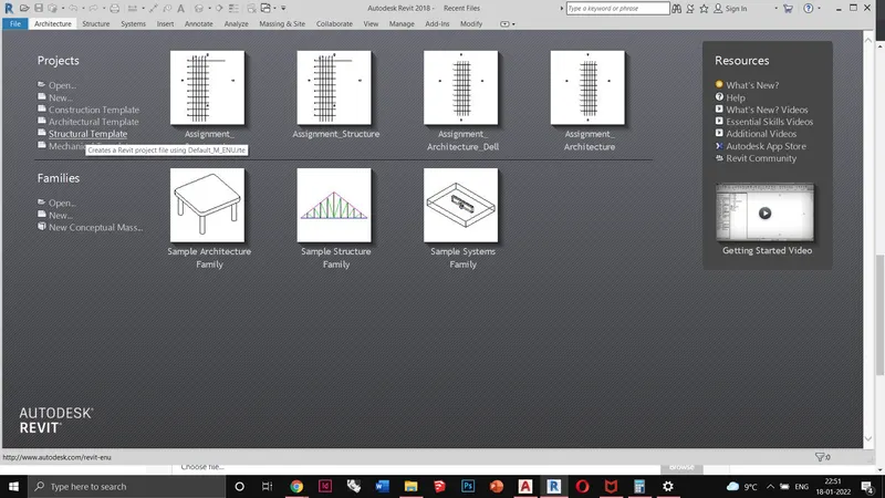
Opening the structure template.
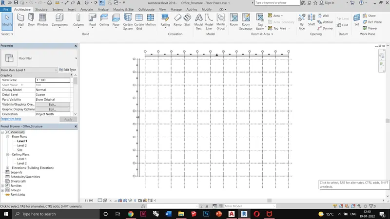
Creating structural grids for the placement of columns.
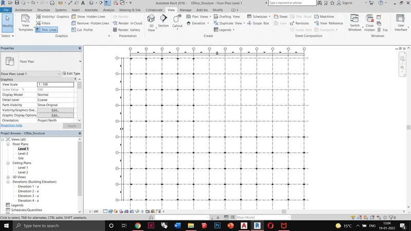
Placing structural columns as per the grids. Column size 400x800
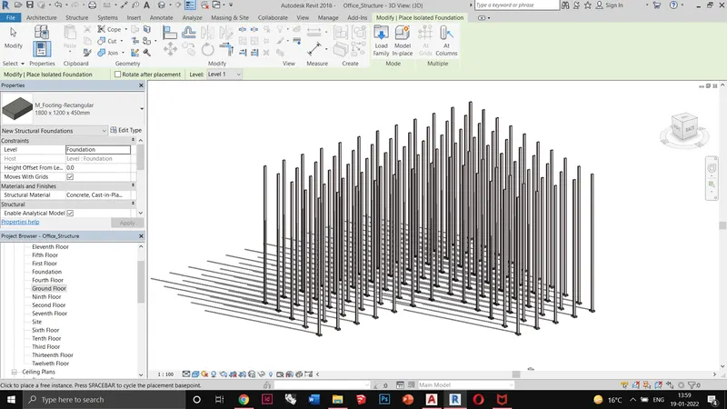
Adding foundation for the columns. Foundation size 2000x3000
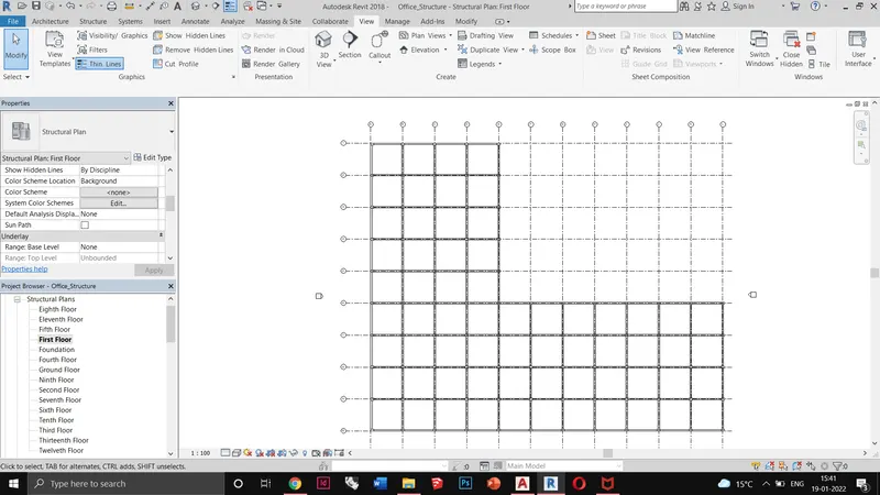
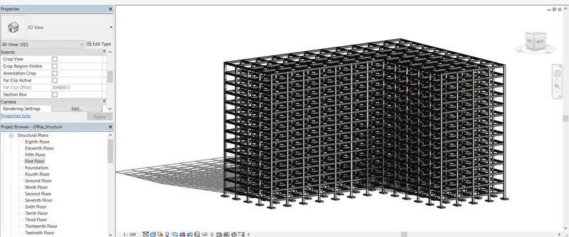
Putting the framing for the floors. Beam size 400x800
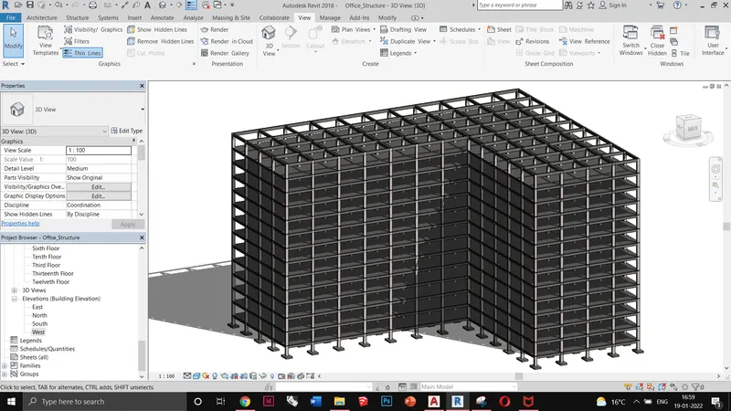
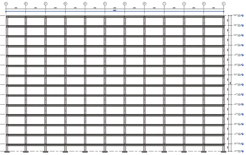
Adding structural floor to the respective floor levels
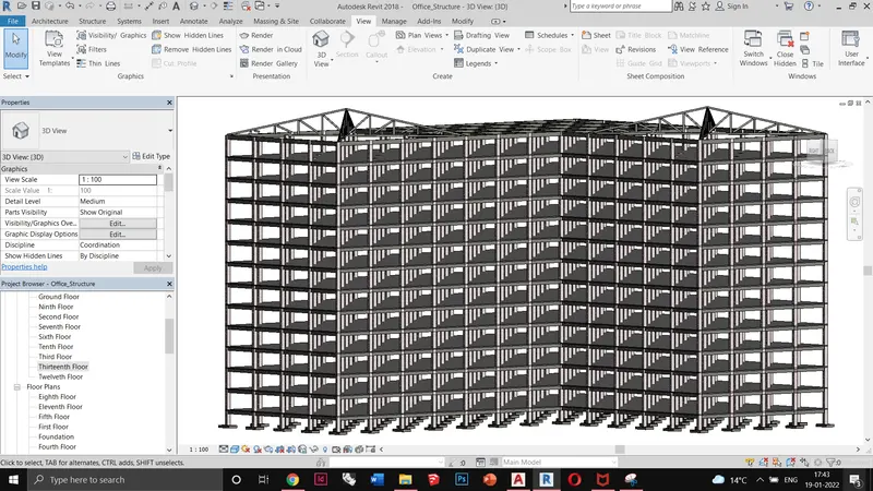
Adding structural roof truss. M_Pratt Gabled Truss-12 Panel
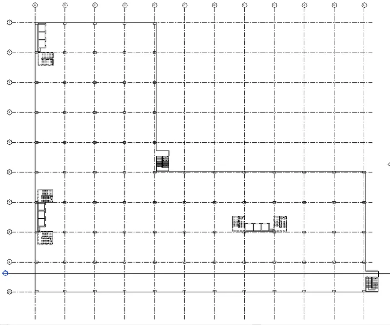
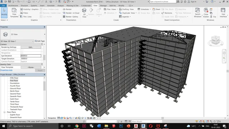
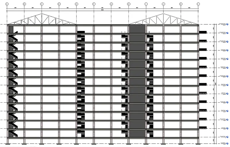
Adding external fire exit staircase, internal staircase, and lifts.
Q4) Ans:
Aim:
To place the following components in the architecture model
a. Wall Layout with appropriate material and finishing
b. Exterior façade with fancy finish
c. Interior partition walls to size rooms
d. Components to add details to a room ( Desk, Chair, Lighting, Plumbing fixtures)
e. Add components such as stairs Elevators
f. Have at least one side of the building with curtain walls and glass panels
g. Include interior and exterior lighting fixtures
h. Place proper topographic components from outside ( Trees, Parking, Plants) to add details to the model
Introduction
* Linking models are primarily intended for linking separate buildings, such as those that compose a campus. We can link architectural models, structural models, and MEP models.
* Linked models are listed in the Revit Links branch of the Project Browser.
Procedure:
* Opening architecture template
* Making it as the central model and linking the structure model from the manage links tab
* Copying the grids and levels from the structure link into the central model. Making floor plan views from the view tab
* Adding external walls, curtain glazing, and interior walls.
* Placing furniture and other items from the Components tab.
* Adding elevators
* Creating a site using topography and creating subregions for distinguishing green and paved surfaces.
* Adding site components such as street lights, trees, parking lot, cars, benches, garbage bins, etc.
Results:
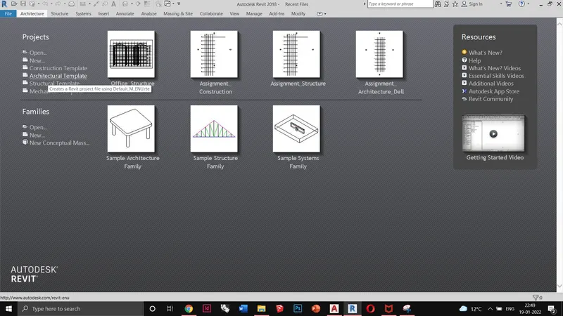
Opening architecture template. Saving it as the central model.
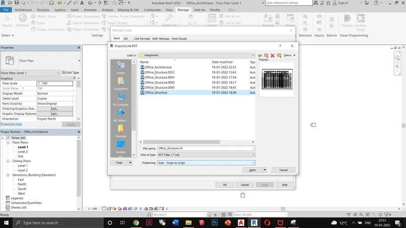
Linking the structural model into this file.
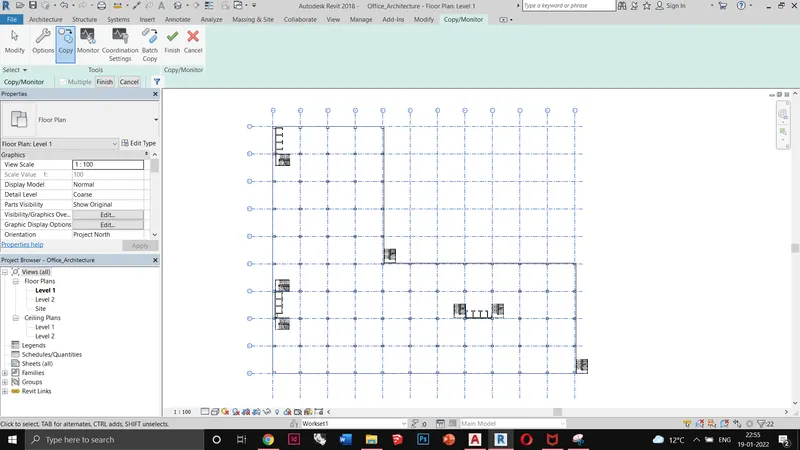
Copying grids & levels from the structural model to work on the architecture template
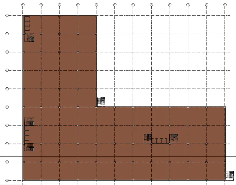
Adding walls and floor finish material.
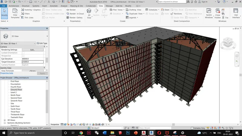
Adding glazing, walls, and structural glazing members.
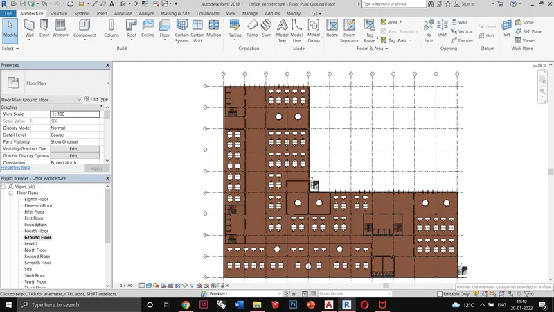
Putting interior walls and furniture
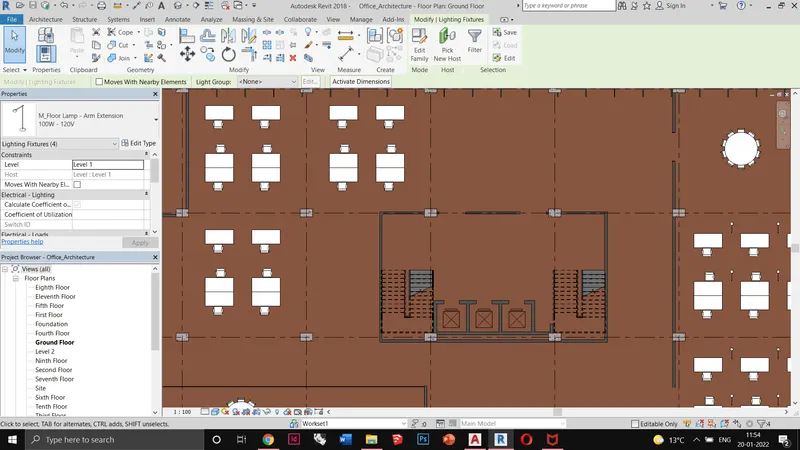
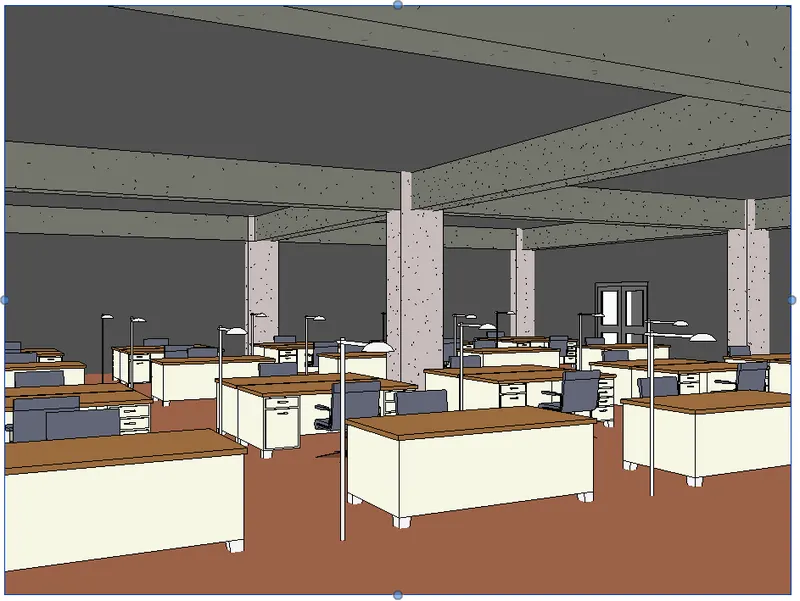
Putting elevators and lighting equipments
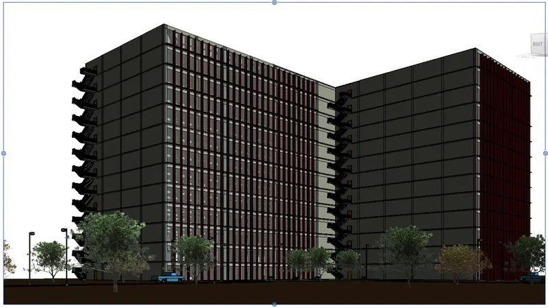
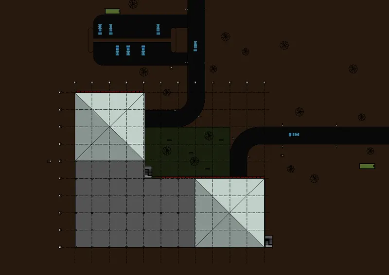
Adding site elements such as street lights, roads, cars, trees, parking
Q5) Ans:
Aim:
To create architectural and structural sheet templates for the following:
a. Floor Plans with Annotations
b. Elevations
c. Sections
Introduction:
To create a standard set of construction documents, create sheets using the desired title blocks.
Add views to the sheets, using the desired viewport templates and view title types. Then save the empty project as a project template.
Procedure:
* Open the architecture model
* Creating sheets and putting the project information
* creating floor plan, elevation and sectional views
* Editing the views using Graphic display options
* Repeating the same steps in structural model
Results:
Architecture Sheets
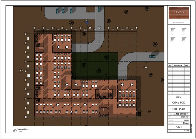
Floor Plan scale@1:200
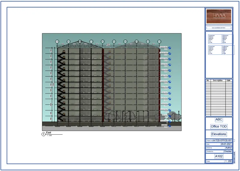
Elevation scale@1:200
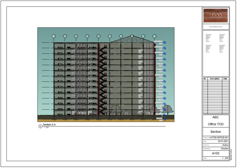
Section scale@1:200
Structure Sheets
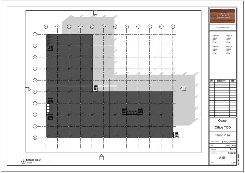
Structural Floor scale@1:200
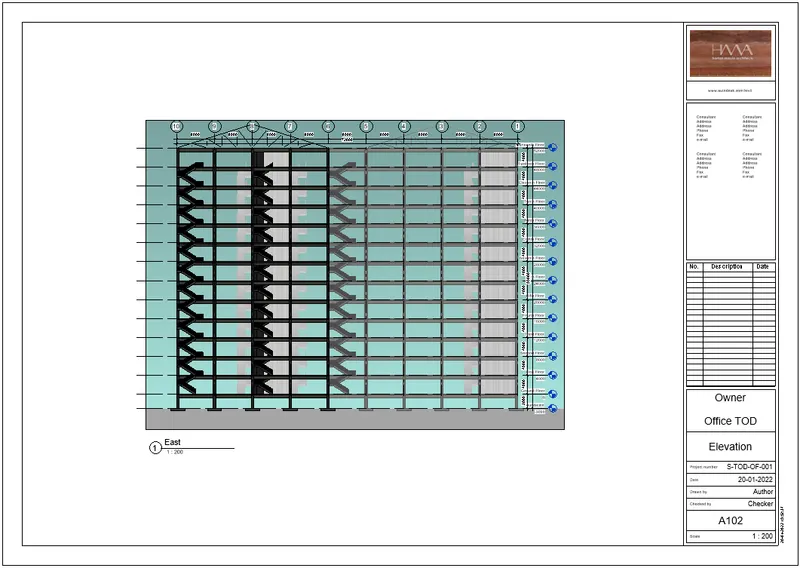
Structural elevation scale@1:200
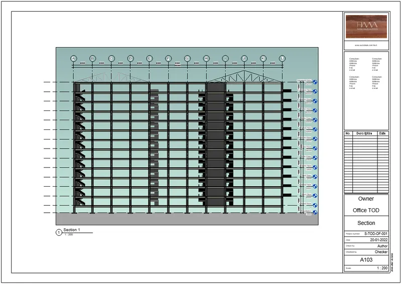
Structural section scale@1:200
Q6) Ans:
Aim:
To render the following views and include them on sheets
a. Rendering from interior rooms
b. Rendering from out showing topographic features
c. Rendering through structural framing
Introduction:
After preparing the 3D view and using the Rendering dialog to select desired settings, click Render to render the image.
Revit begins the rendering process, rendering the entire image progressively. Revit displays a progress dialog, which shows
information about the rendering process.
Procedure:
* Set the view point for render using the camera.
* putting the views on the sheets.
Results:
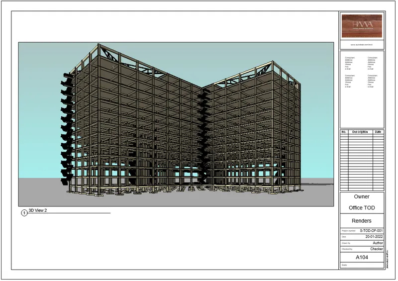
Structural framing render view
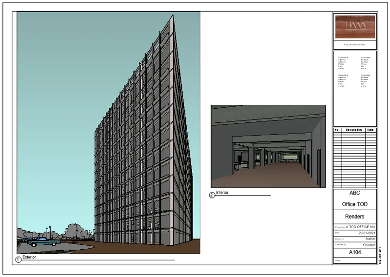
Topographic and interior render view
Q7) Ans:
Aim:
To print the sheets created from structural and architecture model
Introduction:
Once sheets are ready, we can give the print command to save the sheets in our device
Procedure:
* For print go to file< print<change it print to pdf< select sheet size
Results:
I am uploading the pdf files.