Creating Architectural and Structural model with 3D rendering using REVIT
1. Multi-Unit Residential Apartment is choosed from above options
2. The geographic and location details for my project modelling, based on assumptions of multi-unit residential Apartment.
- The road width of this project is 60 Feet.
- The height, area limitation and safety measure are followed by the NBC.2005.
3.
Aim: To create the Column, beam, foundation, roof and stairs in residential unit.
Tools used:
- Collaborate
- Stairs
- Column
- Shaft
- Grid
- Beam
- Foundation
- floor
Procedure:
Step 1:
- Open Structural template
- Draw horizontal and vertical grids
- Save the file into your local computer as Str temp
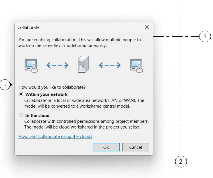
- Click manage tab and choose colloborate
- Make the file as central model
Step 2:
- Open Architectural template
- Draw horizontal and vertical grids
- Save the file into your local computer as Arch temp
- Click manage tab and choose colloborate
- Make the file as central model
Step 3:
- Open a saved architectural model and click insert tab
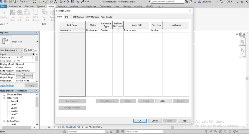
- Click insert revit link and choose structural template in architectural model
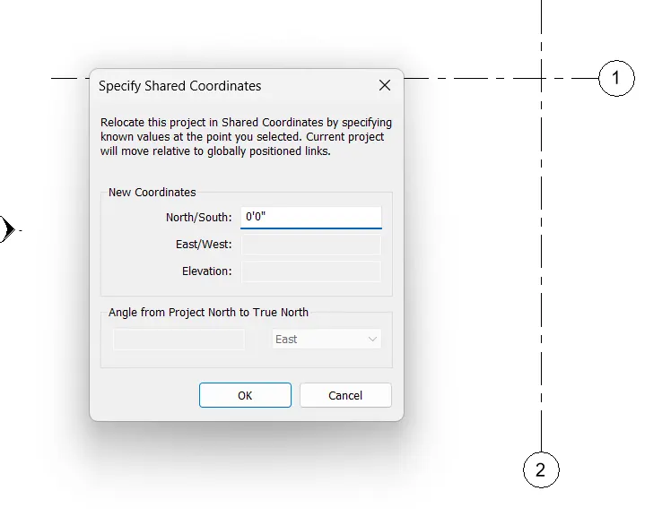
- Choose manage tab click shared coordinates then click 0' and pin point the grids
- Now both the architectural and structural template are linked successfully
Step 4:
- Click structure tab and select column
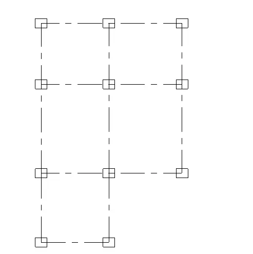
- Place the column and place it on all grids
- Similarly select footings and place it in the grids
- Place the floor and place it
- Make it into 3D view
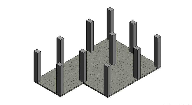
Step 5:
- Using Copy Monitor tool make the copies of floors upto roof level
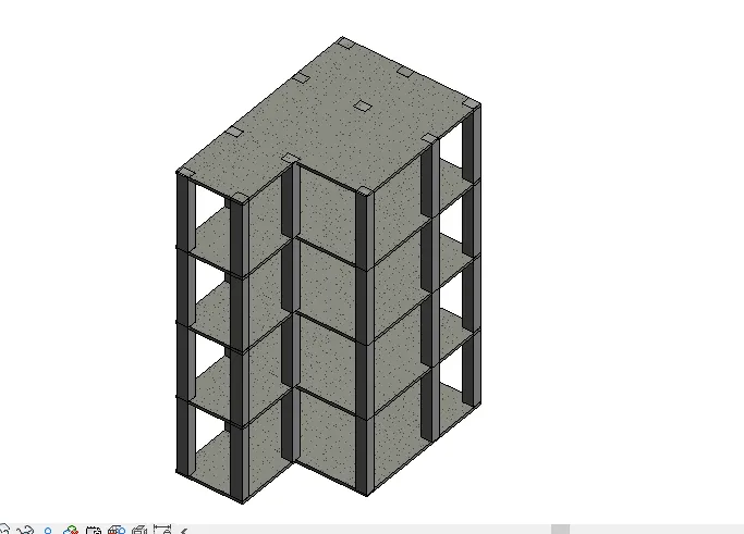
Step 6:
- Click Architectural tab and choose stairs
- Draw the stairs as per NBC
- After drawing the stair click copy and paste it into the aligned levels
- Click Architectural tab and choose Shaft tool
- Draw the shaft area around the stair
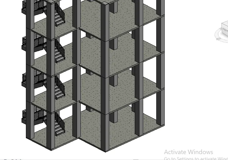
Result: Structural model is drafted
4.
AIM: Use the architectural model, include the following components based on the type of structure selected
Tools used
- Architecture
- walls
- Component
- Load family
- Ceiling
- Floor
- Doors
- Windows
- Staircase
- Railings
PROCEDURE:
- Now go to the architectural template which has created
- Copy the grids which were created in the previous structure template and copy it.
- With the help of paste from clipboard option paste the grids in the architectural template.
- Select the grids and pin it .
- Click the elevation and create the levels required from architectural tab
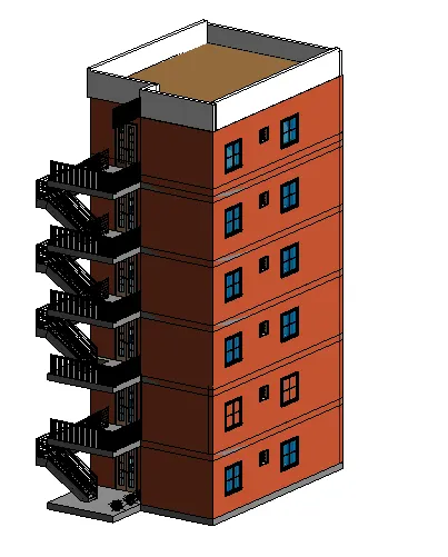
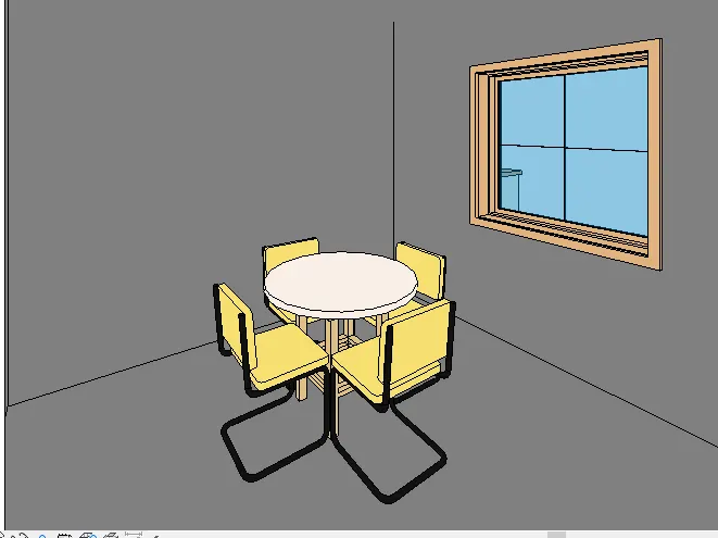
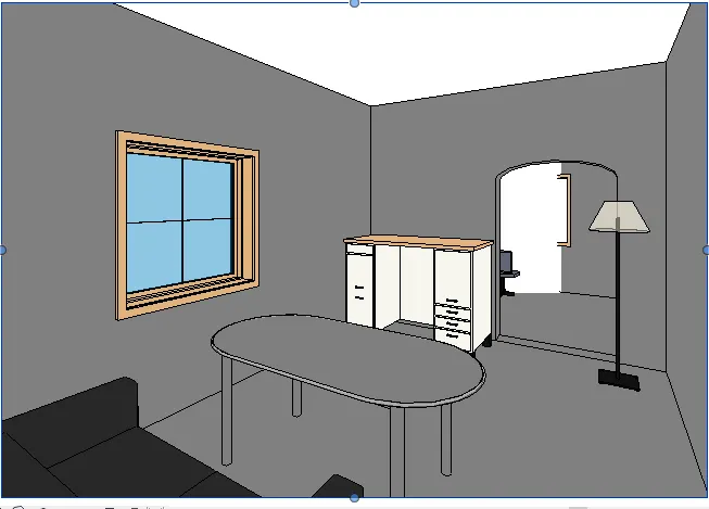
Result: All selected components are inserted in it
5.
AIM: To Provide a set of drawings in an architectural and structural model to list the following details with categories and appropriate sheet templates floor plans, elevations, and sections
Tools used:
- Insert
- Sheets
- Load families
- Edit sheets
- load image
- view
Procedure:
- Floor plan of the building
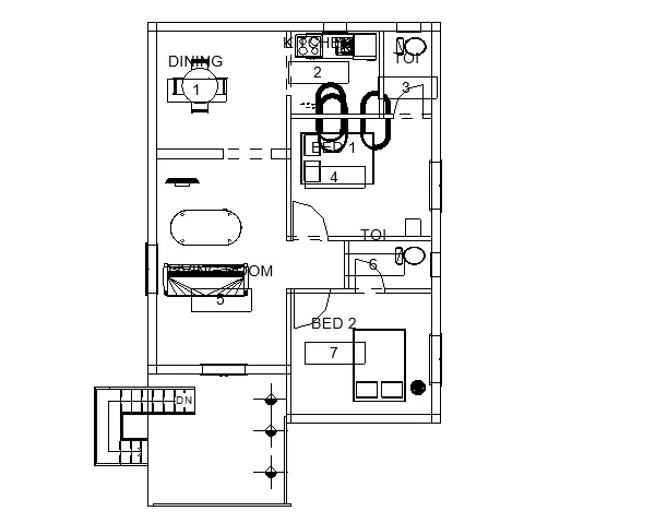
- Elevation
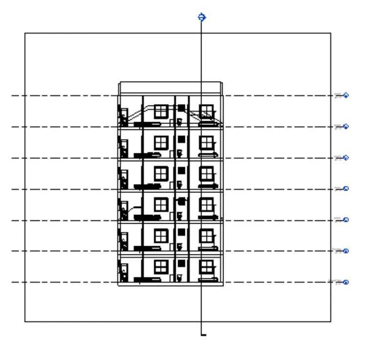
- Section
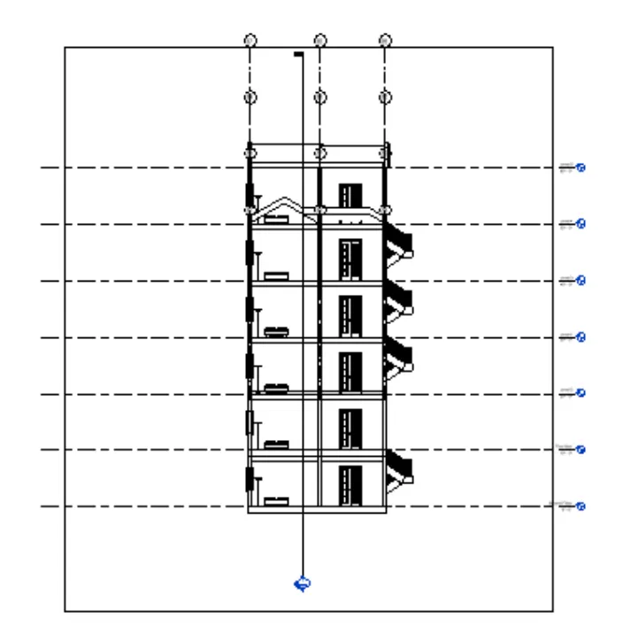
Result: Set of drawings in an architectural and structural model
6.
Aim: Render images of the 3D model
Tools used:
- Render
- Region
- Style
- Scheme
- Sheet
PROCEDURE:
- Open 3D view and set the view to take the picture where, we want to render the area.
- Click view menu and click render option.
- Render dialog box are appears.
- Select region option and crop the image in region.
- Then, we can change the style of render images , schemes, lighting options and finally, click render in it.
- Then the render image will be appears into more realistics than other and it can used to better presentation of our clients also.
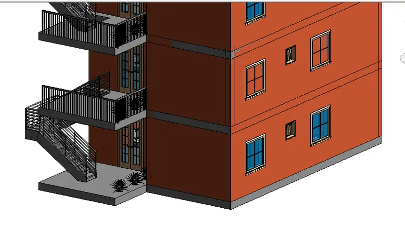
Result: 3D images are rendered
7.
AIM: To Print the set of drawing sheets created and submit the drawings from the architecture and structure model.
Tools used:
- File
- Setup page
- Select the plotter
Procedure:
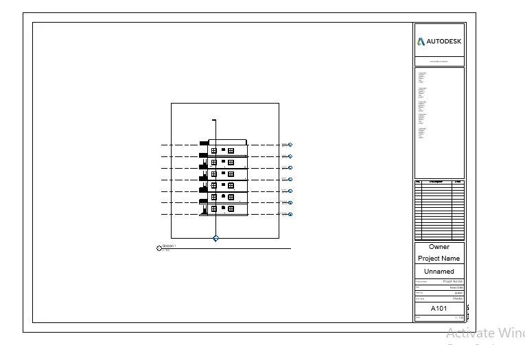
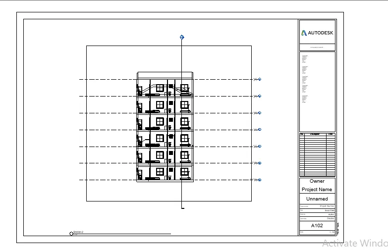

Result: Set of drawing sheets are created
Note: It is copied from Live session challenges