Creating Architectural and Structural model with 3D rendering using REVIT
1) Select the type of structure you want to build from one of the three below:
a. Multi-Unit Residential Apartment
b. Office Buildings
c. School
Solution:
Multi-Unit Residential Apartment
2) Assume reasonable assumptions for geographic and location details for your project modeling. Based on assumptions and type of structure selected identify the modeling requirements from NBC
Solution:
- Building is constructed in the residential area.
- Building is constructed in the plain area (geographic)
- Infront of building there is a road with the width of 10'.
- As per the NBC, the height limit will be given in NBC part V-1.
- The size of the rooms also given in the NBC part V-1.
- All the space in all side has been taken care.
3) Using the structural model, include the following components based on the type of structure selected
a. Foundation – Isolated / Wall/Matt Foundation
b. Columns
c. Beams Connected to Columns
d. Roof Framing/ Truss
e. Floor / Decks
f. Floor Openings for Elevators and Stairs
Solution:
- Draw the Grids as Per the Architecture Plan.
- Place the Columns as per the requirement to support the Structure.
- Also define the Levels to the Columns From Natural Level to Terrace and Stairs and Elevator Columns Should give the levels From Natural level to the top of the Building.
- Now place the Isolated Footing to all the columns at Natural Level at the center of the column and also as per the Column Orientation.
- Now place the Plinth Beams at Plinth Level.
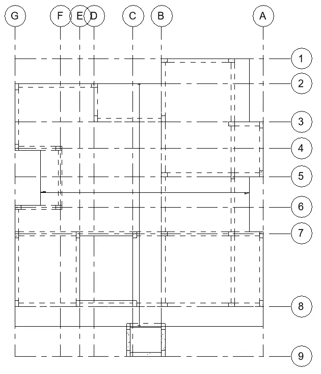
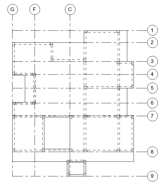
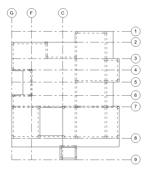
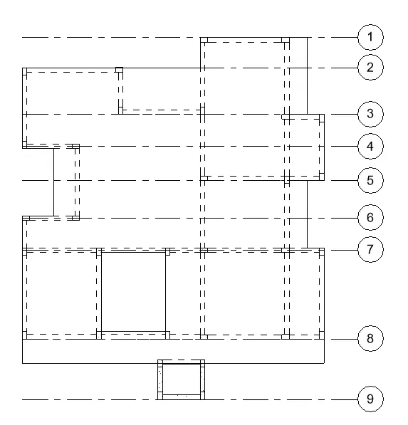
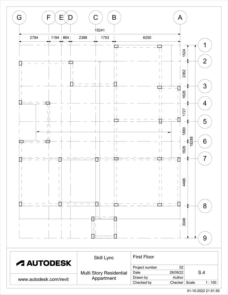
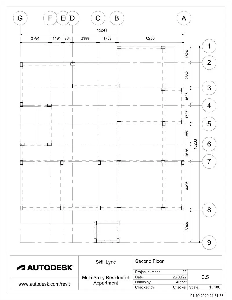
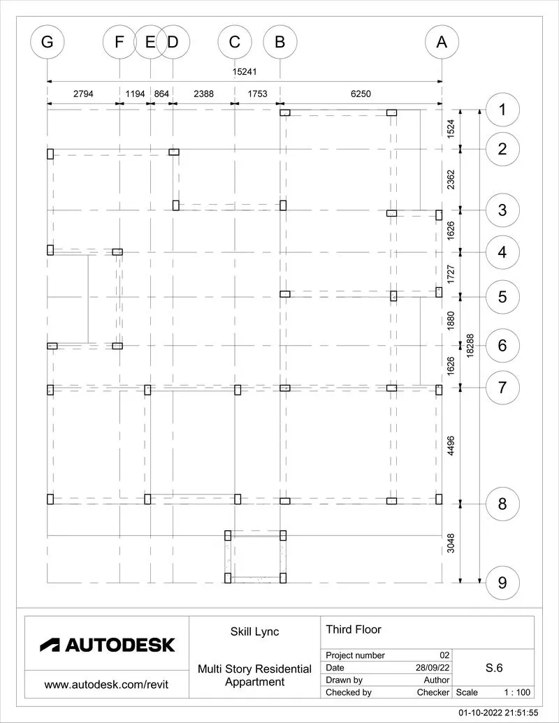
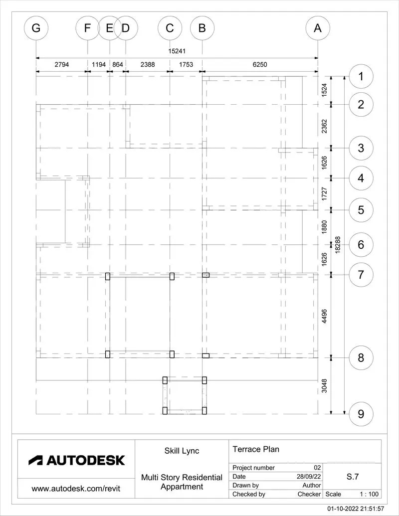
- Similarly Creating First, Second, Third, & Terrace Beam Plnas.
- First Floor:
- Second Floor:
- Third Floor:
- Terrace ffloor:
- First Floor:
- Now draw the Top Building Beam Plan of the roof:
- Now Draw the Structural Floors as per the planning.
- Now copy the floor From First Floor to Second Thirdd and Terrace .
- Now Create the Structural Shaft Opening for the Stairs.
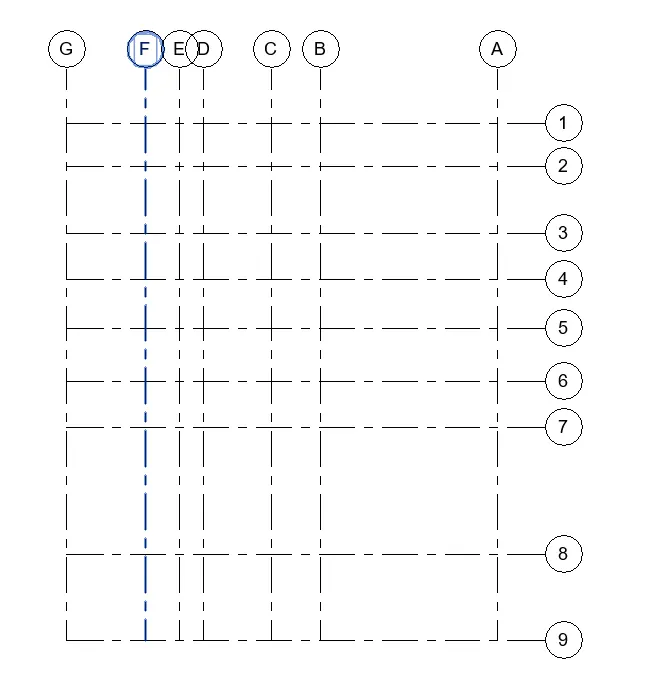
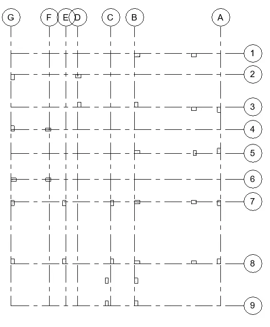
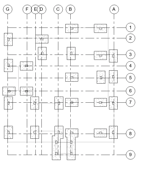
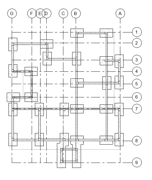
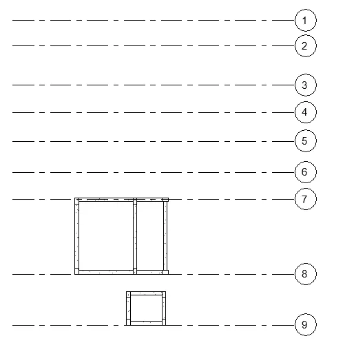
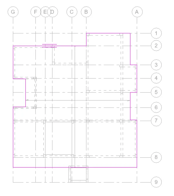
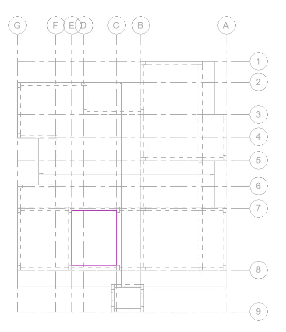
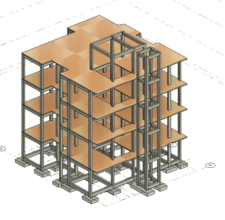
Final Result:
4) Using the architectural model, include the following components based on the type of structure selected
a. Wall Layout with appropriate material and finishing
b. Exterior façade with fancy finish
c. Interior partition walls to size rooms
d. Components to add details to a room ( Desk, Chair, Lighting, Plumbing fixtures)
e. Add components such as stairs Elevators
f. Have at-least one side of the building with curtain walls and glass panels
g. Include interior and exterior lighting fixtures
h. Place proper topographic components from outside ( Trees, Parking, Plants) to add details to the model
Solution:
- Draw the topography Surface of the Site.
- Draw the Building Pad on the topography surface.
- Draw the Boundry walls to the Building on the natural level.
- Draw the walls on the Plinth Level.
- Use wall tool in the Architecture tab.
- Draw the External wall With the Finish Exterior Material.
- Draw the Internal wall to make the rooms required.
- Make the walls Level upto First Floor Height.
- Place the Doors on the First floor as per the Required Size.
- use DR Command to insert the Door.
- Load family of the Door as per the Requirements.
- Duplicate the Family of the Door and set the size as per the requirements.
- Place the Windows on the First floor as per the Required Size.
- use WN Command to insert the Window.
- Load family of the Window as per the Requirements.
- Duplicate the Family of the Window and set the size as per the requirements.
- Draw the Plinth Level Ploor Drom plinth level to the Normal Level to make the perfect level of the Ground Floor.
- Make the Sitting floor outside the Rooms Living Etc. as per the requirements.
- Insert Components to add details to a room ( Desk, Chair, Lighting, Plumbing fixtures).
- Now Open the Ceiling Plan of the Plinth Level.
- Sketch the Ceiling.
- Now add the Lightning fixture to the Ceiling.
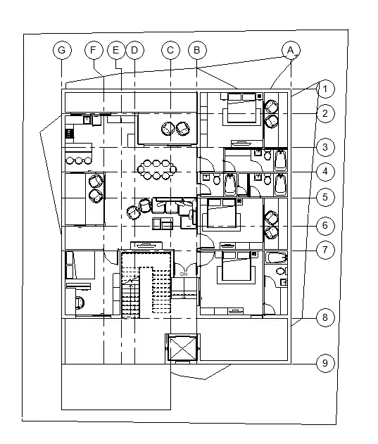
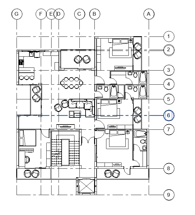
- In the Floor Plans add the CM Desk Chair Dining table Sofa Bed etc.
- Now Draw the Stair Case to the First Floor From the Ground Floor.
- Now Copy the Ground Floor plan & Paste it to the First, Second, third Floor as it is.
- Now Insert the Lift Elevator for the Connectivity of the floors.
- and make wall for the elevator.
- Now make the roof at the top of the staircase and lift.
- Draw the Railing to the Balcony.
- Draw Railing to the Terrace and the Roof.
- Access to the Roof Rom the Terrace..
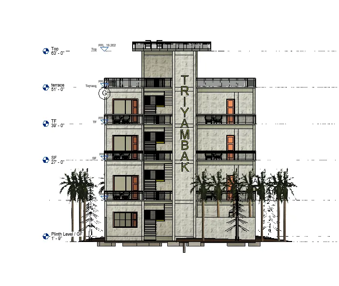
- Write the name of the Building on the Front Elevation.
- add the Planting to the Topography are near the building and inside the building.
- now Check the 3D View.
Final Result:
5) Provide a set of drawings in an architectural and structural model to list the following details with categories and appropriate sheet templates included
a. Floor Plans with Annotations
b. Elevations
c. Sections
Solution:
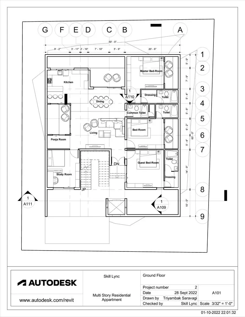
Architectural Model:
- Floor Plans:
- Elevation
- Section
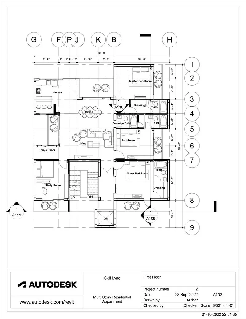
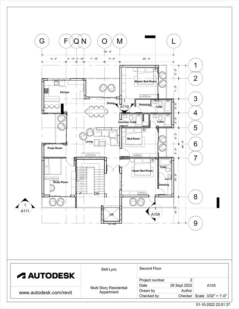
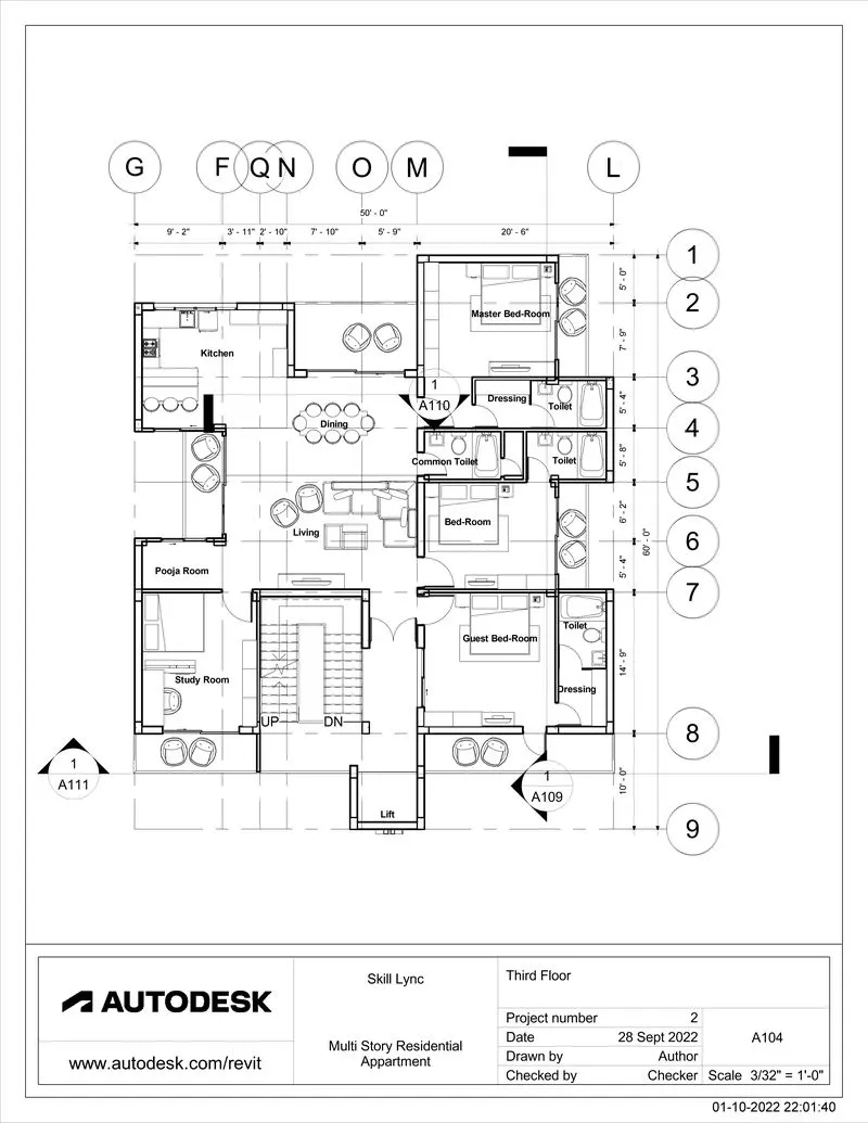
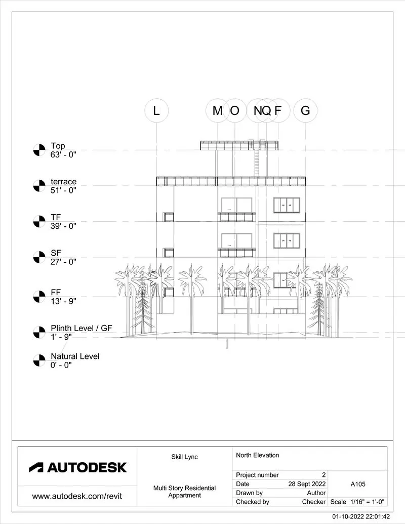
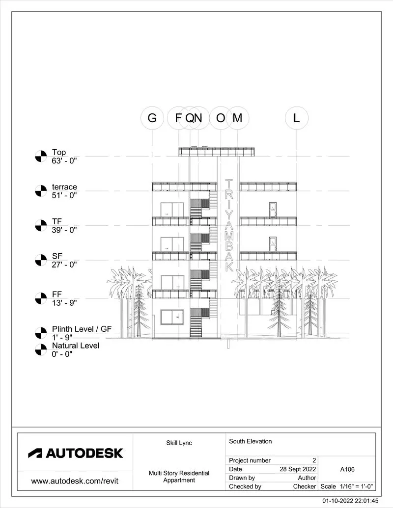
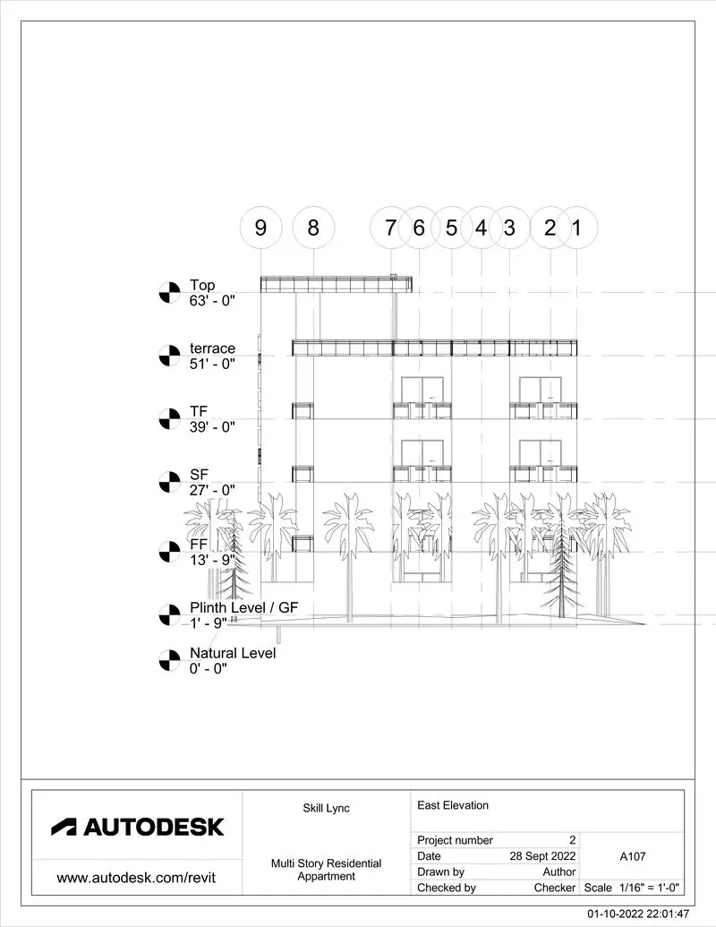
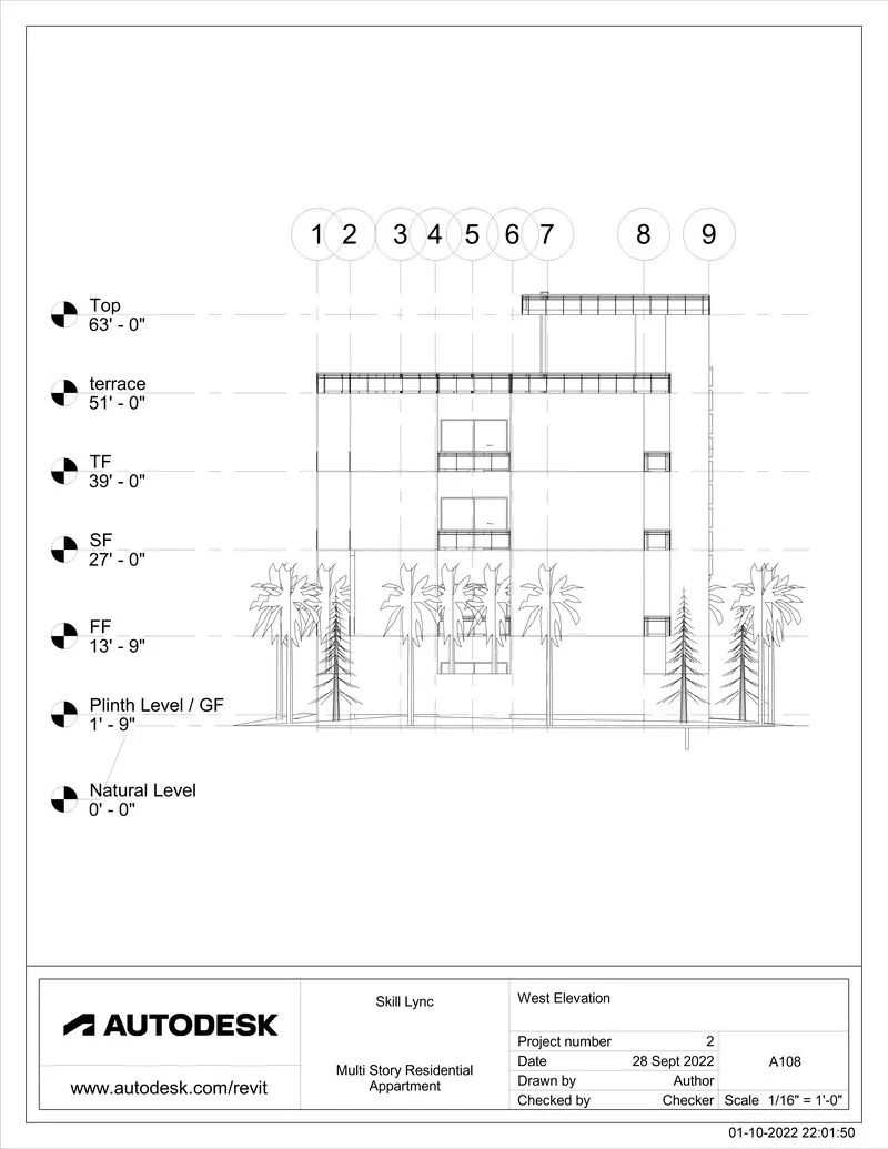
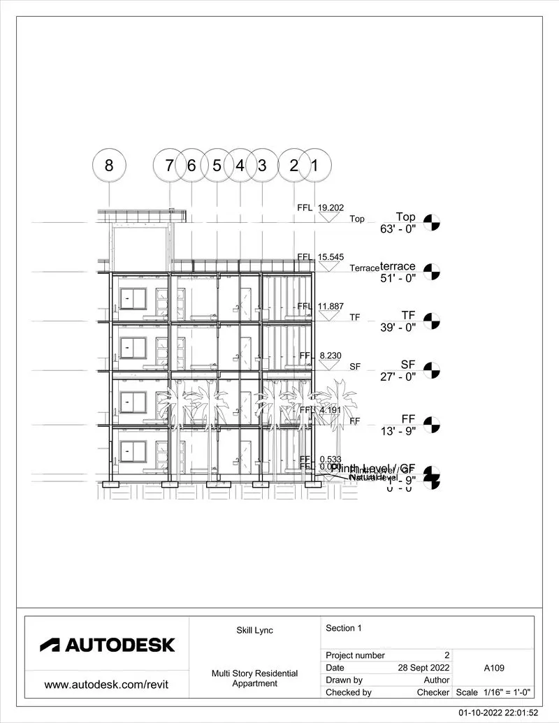
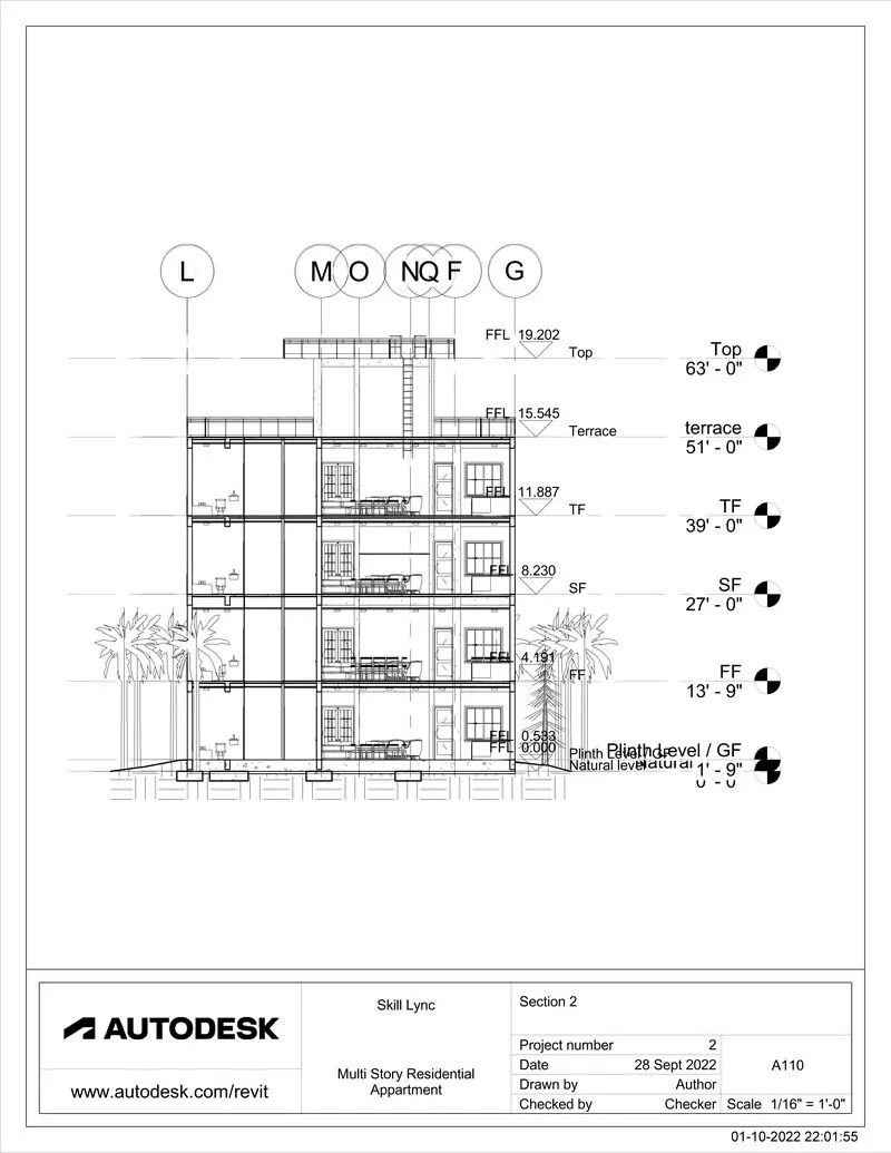
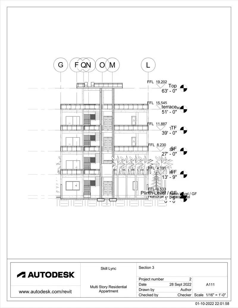
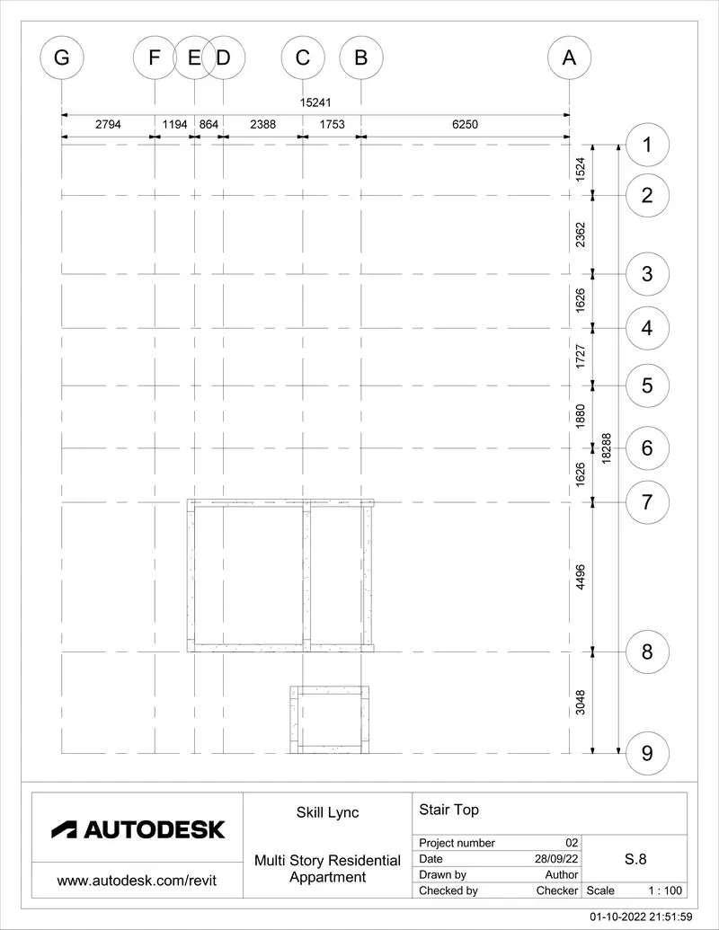
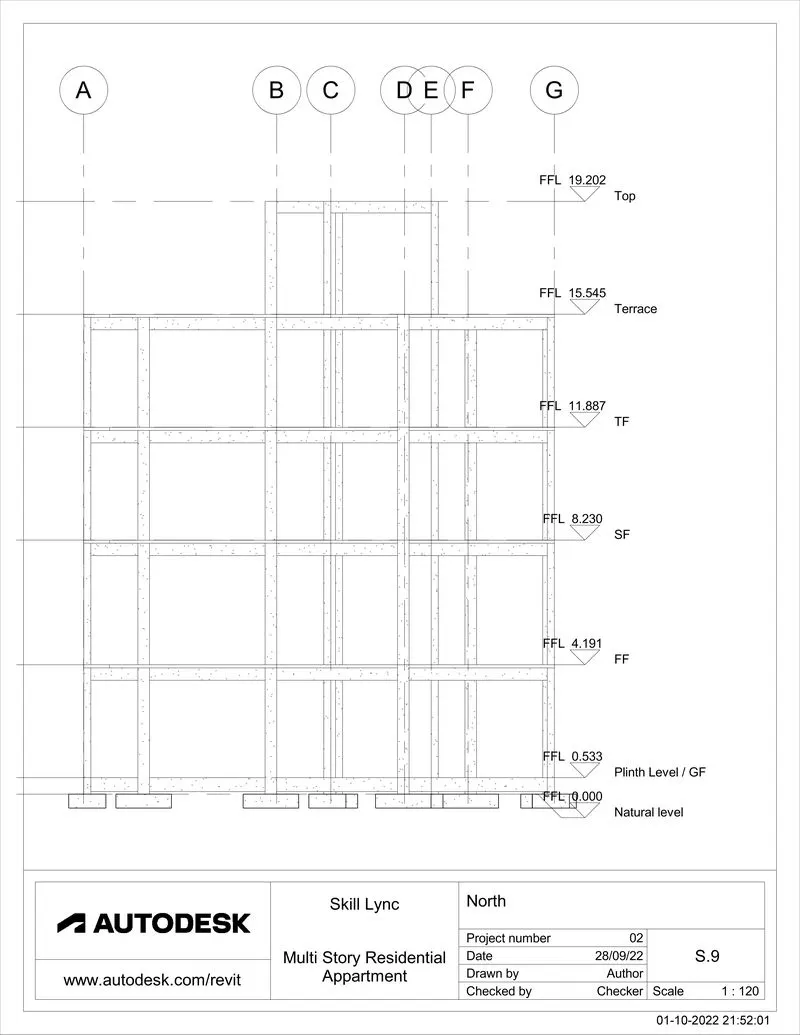
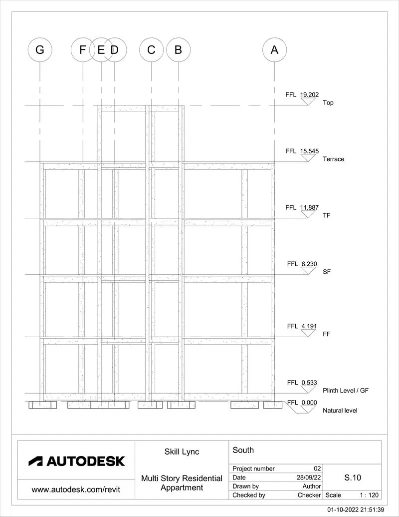
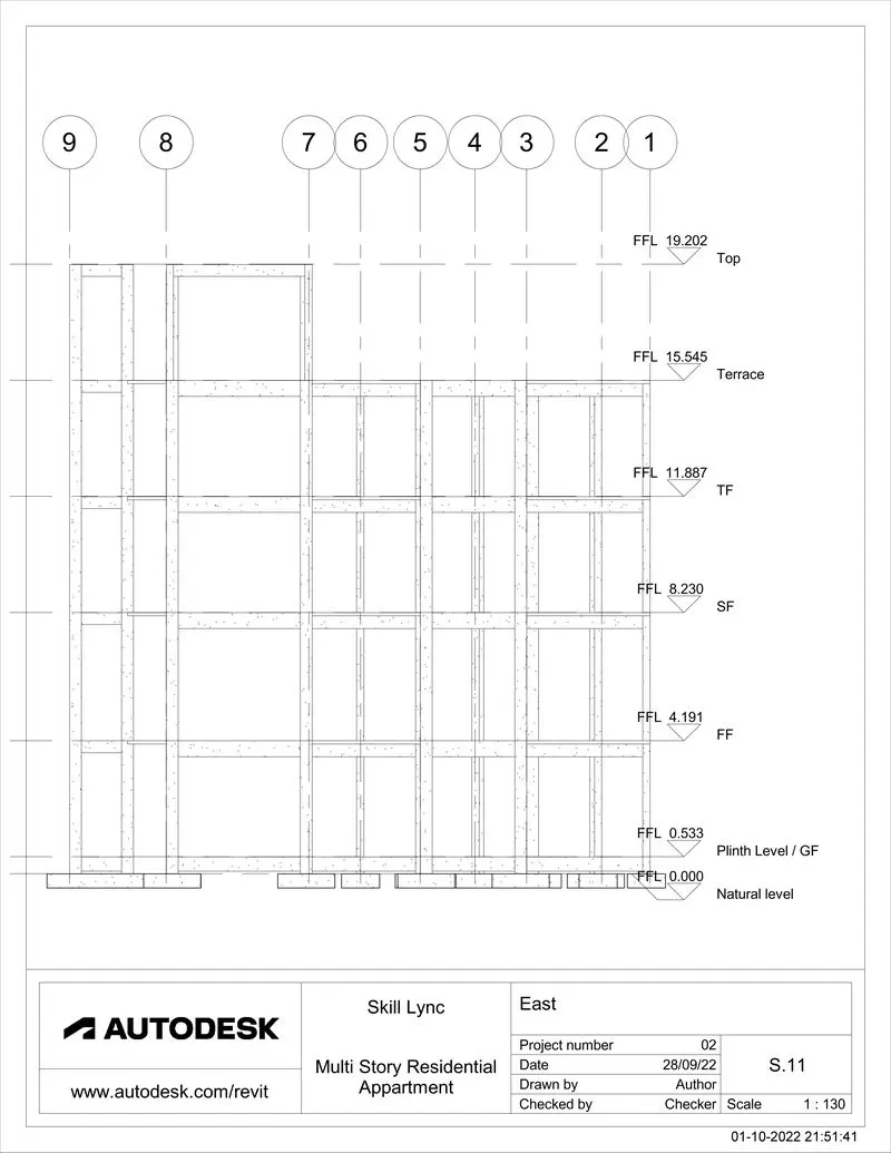
Structural Model:
- Floor Plans:
- Elevation:
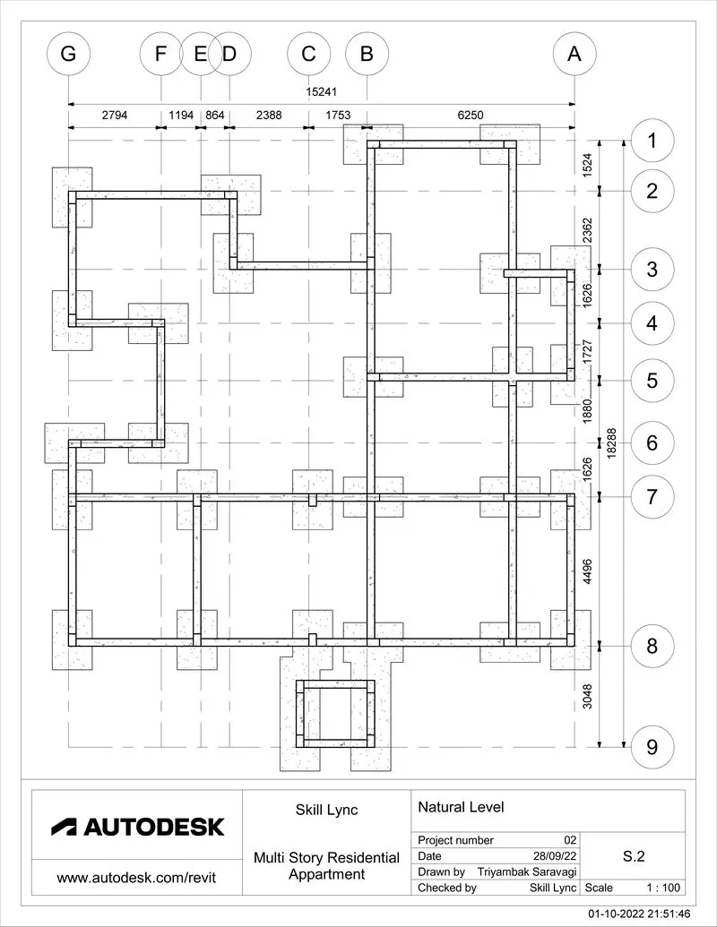
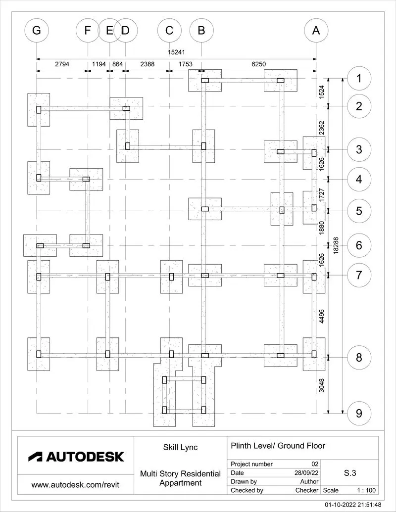
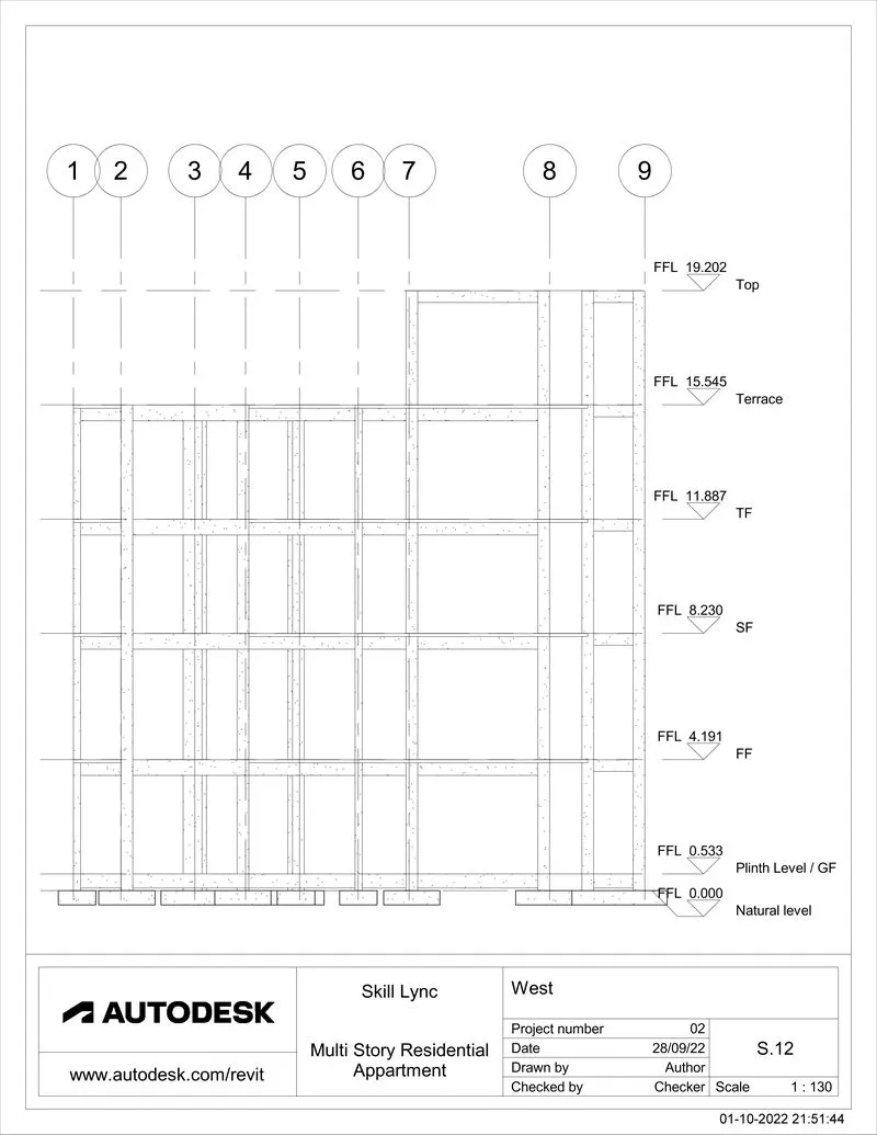
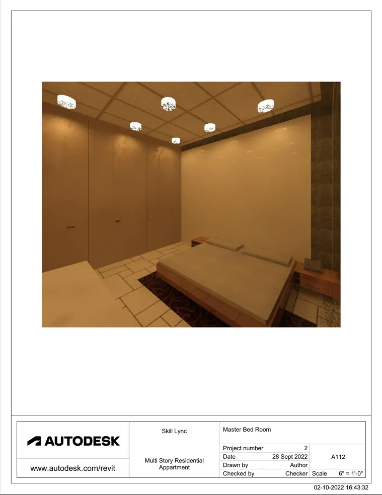
6) Using the Rendering settings, Render images of the 3D model produced and include the rendered images to the drawing sheets
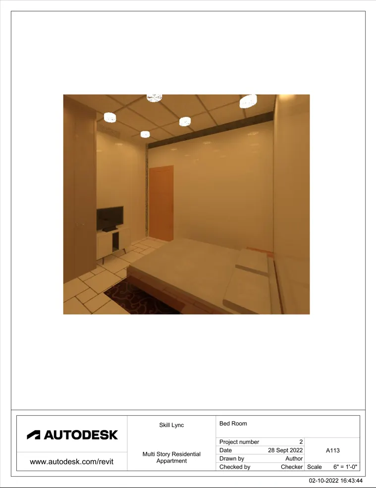
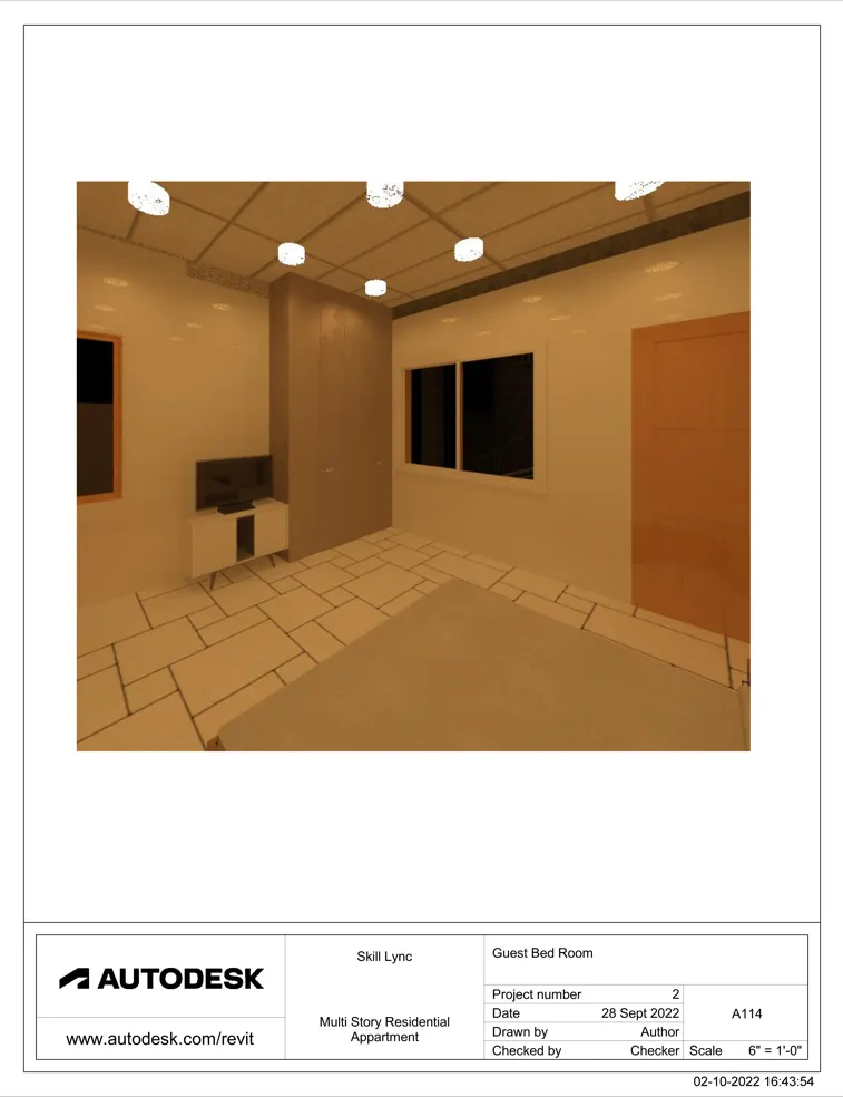
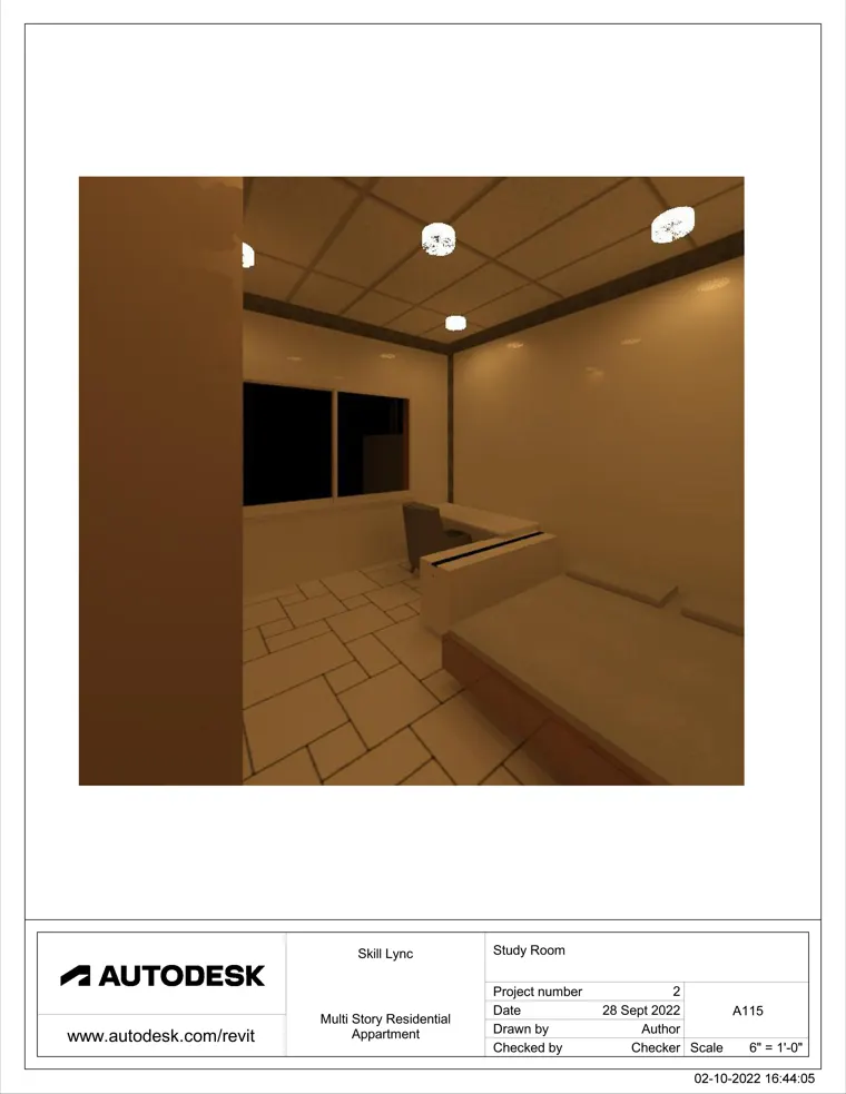
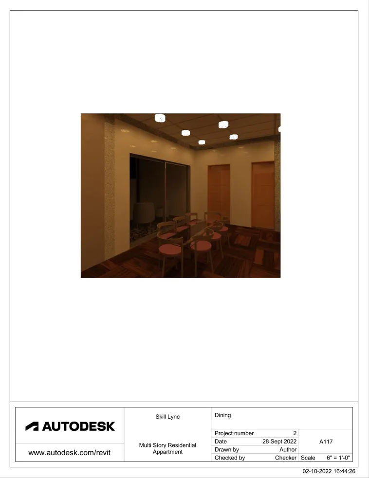
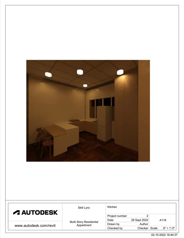
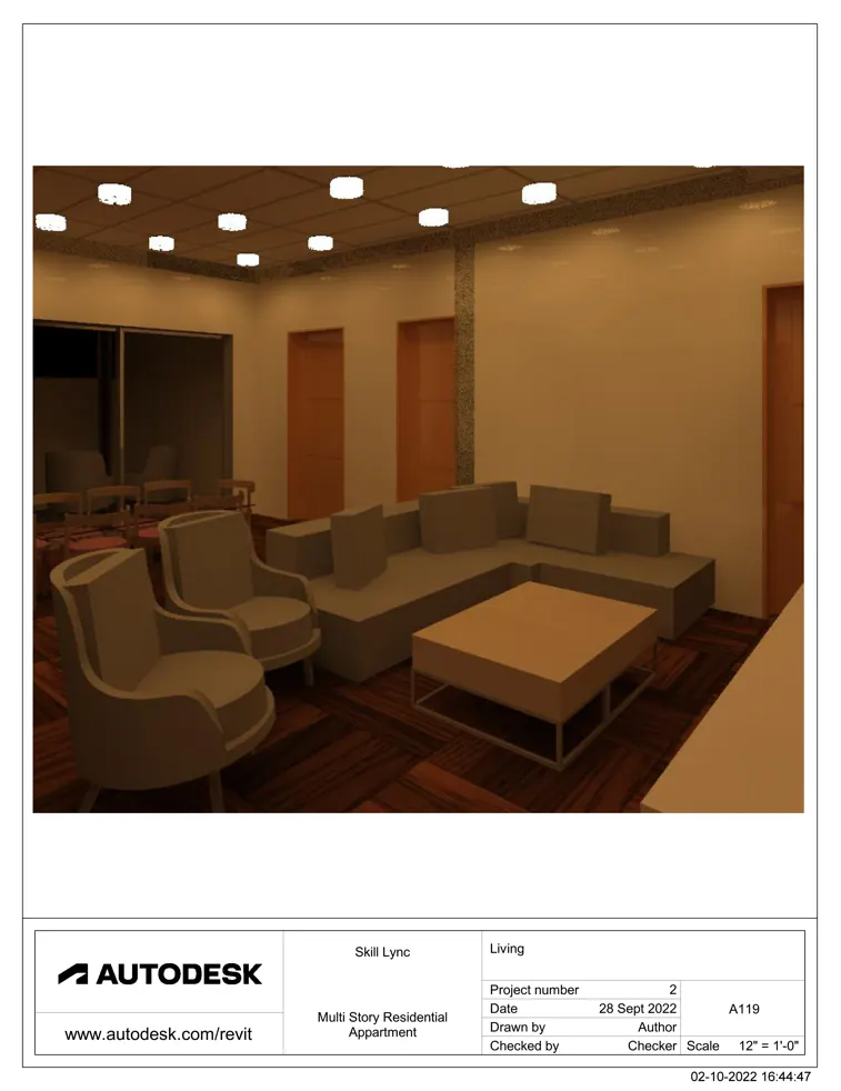
a. Rendering from interior rooms
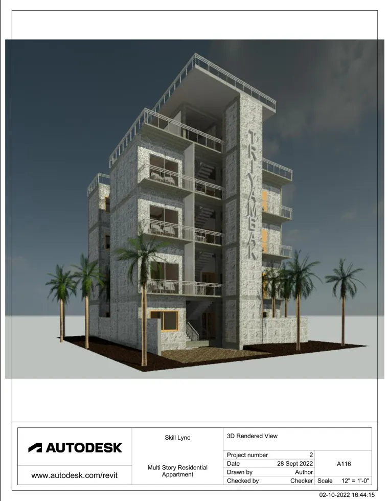
b. Rendering from out showing topographic features
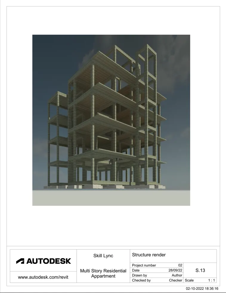
c. Rendering through structural framing
Solution:
- Rendering from interior rooms
- Rendering from out showing topographic features
- Rendering through structural framing
7) Print the set of drawing sheets created and submit the drawings from the architecture and structure model
Solution:
See the Attached Files PDF.