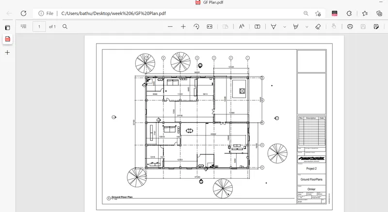
Creating Architectural and Structural model with 3D rendering using REVIT
1) Select the type of structure you want to build from one of the three below:
a. Multi-Unit Residential Apartment
b. Office Buildings
c. School.
Aim: To select type of structure for the project.
Procecdure
We need to select one of the following and then create a tamplate for that.
Result:
I would like to slelct the Multi-Unit Residential apartment.
2) Assume reasonable assumptions for geographic and location details for your project modeling. Based on assumptions and type of structure selected identify the modeling requirements from NBC?
Aim:
To assume the resonable details for the geographic and location details for the project and model requirement for the NBC.
Introduction:
While create any project we need to sure about the Nation building code guidelines becouse they are made for the safety and for environment.
By following the guidelines we can create a better enivronment for the structure.
Procedure:
In this i would like to choose the location as the hyderabad for my project.
NBC for Multi-Unit residential appartment in hyderabad are;
- The open space around the building should not be less then 4.5M.
- The type of construction as type 2 construction, the FAR value for the business building shall be taken as 2.9.
- The plot size is taken as 40Mx70M i.e., 2800m2m2 and indivigual floor area 2000m2m2. hence, FAR value is ontained as 2.14.
- The widthe of the road abutting is taken as 9m (30').
Result:
Hence the geographical location and the project model details has been given according to the NBC.
3) Using the structural model, include the following components based on the type of structure selected
a. Foundation – Isolated / Wall/Matt Foundation
b. Columns
c. Beams Connected to Columns
d. Roof Framing/ Truss
e. Floor / Decks
f. Floor Openings for Elevators and Stairs.
Aim:
To create a components using a structural model.
Introuction:
creating the structural models in the structural template with respect to the model helps archiatect to check the model with the project.
Procedure:
First we need to structural file and then we need to go to the structural tab.
Then select the foundation isolated
Then click on at all grids at top right and click on ok.
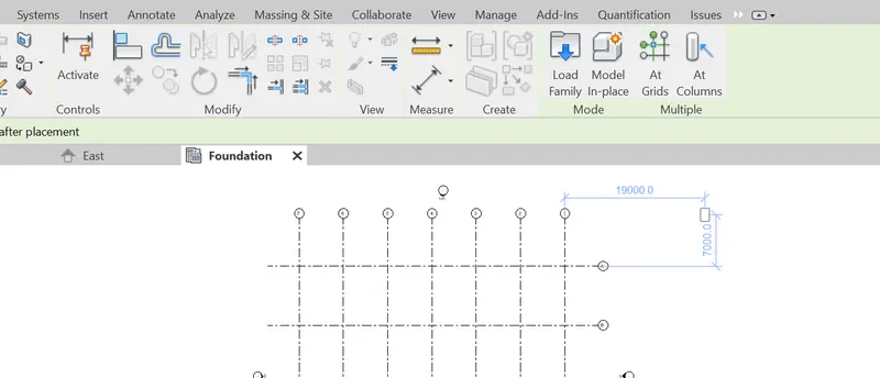
Now we can see the founfations has been added to the level.
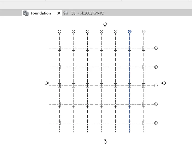
Now to place a columns we need to structural tab againa and then click on the column icon on top left.
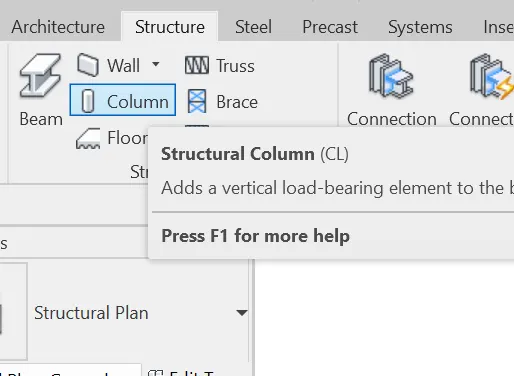
Noe select at all grids on the top rignt and then select all the grids and then click on tick icon.
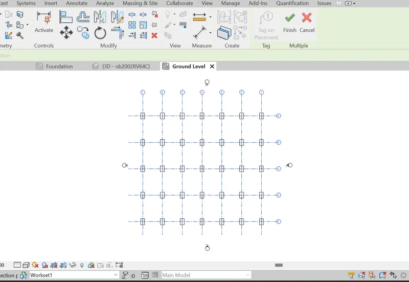
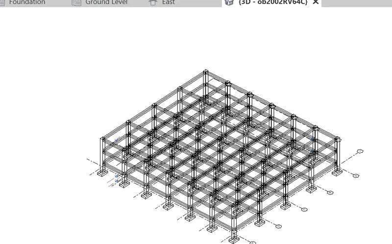
To check the colums has been added we need to go to 3D view to check them.
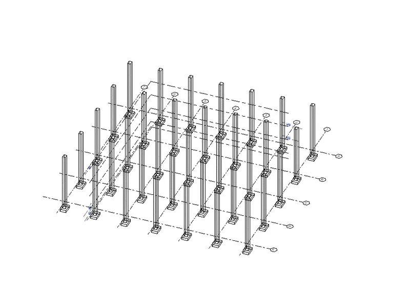
Now to create beams we need to go to structural tab again.
Select the beam option on top left of the structural tab.
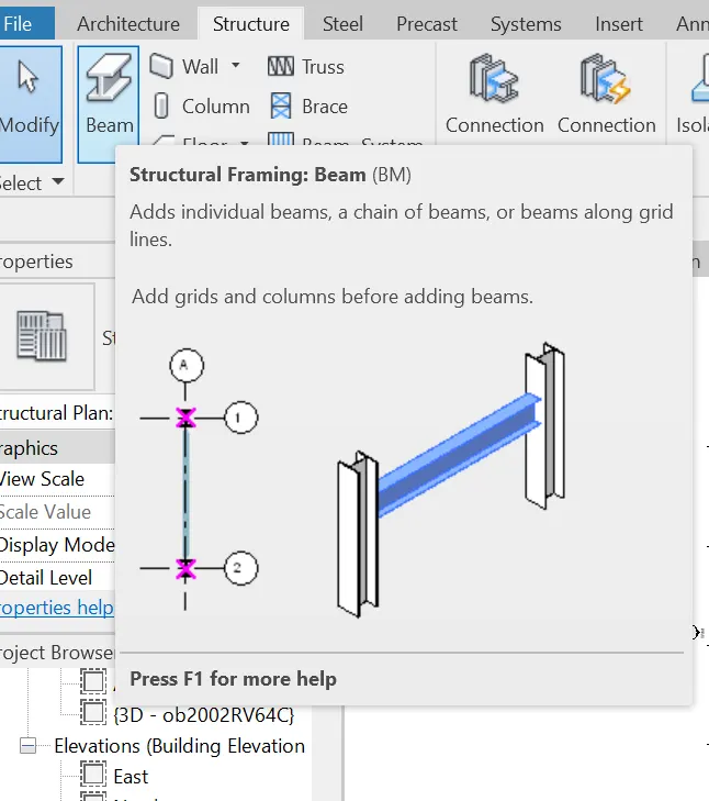
Now select the appropriate beam from the property browser and then select at all the grids icon and select the grids.
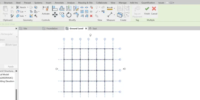
Now click on the finish to see the beams in the project. In the 3D view.
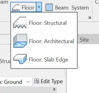
To create a floor in the project go to the structural tab and then select floor icon.
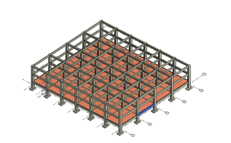
Now select the ground floor and select the cornersof the floor by picking the line.
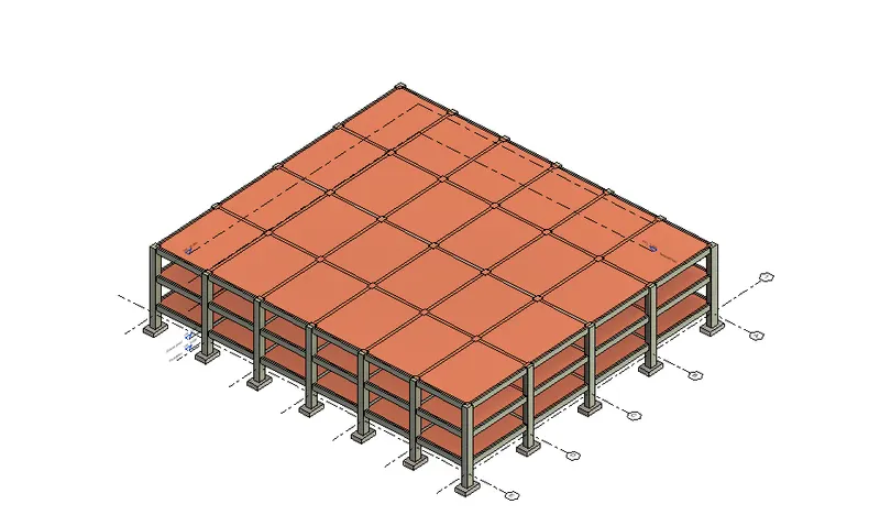
add same for as all the floors.
Now to provide floor openings and the stair case openings. go to architecture tab on the top right we can see the shaft opening icon click on that.
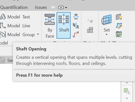
now select the place for the shaft opening and click the ok button to finish opening.
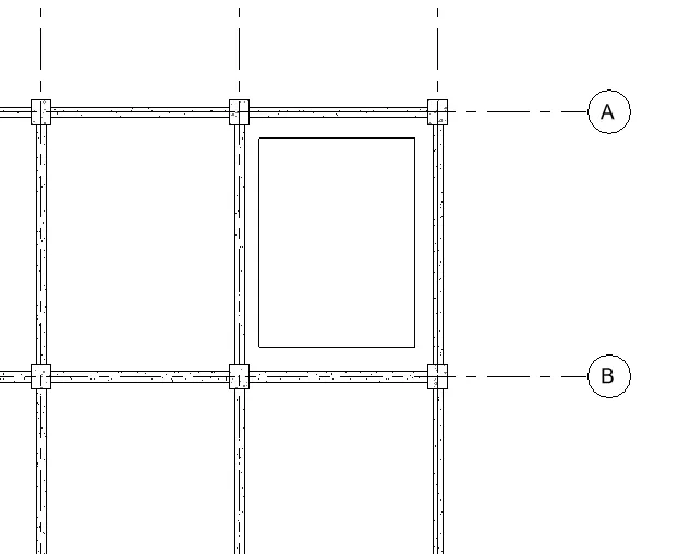
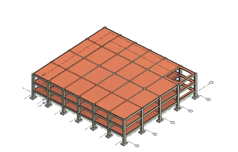
Now we can see the shaft opening in the 3D view.
4) Using the architectural model, include the following components based on the type of structure selected
a. Wall Layout with appropriate material and finishing
b. Exterior façade with fancy finish
c. Interior partition walls to size rooms
d. Components to add details to a room ( Desk, Chair, Lighting, Plumbing fixtures)
e. Add components such as stairs Elevators
f. Have at-least one side of the building with curtain walls and glass panels
g. Include interior and exterior lighting fixtures
h. Place proper topographic components from outside ( Trees, Parking, Plants) to add details to the model?
Aim:
To create a architectural model with all the following details in the project.
Introduction:
Including all the project elements from the project by collaberating with the structrual team.
Procedure:
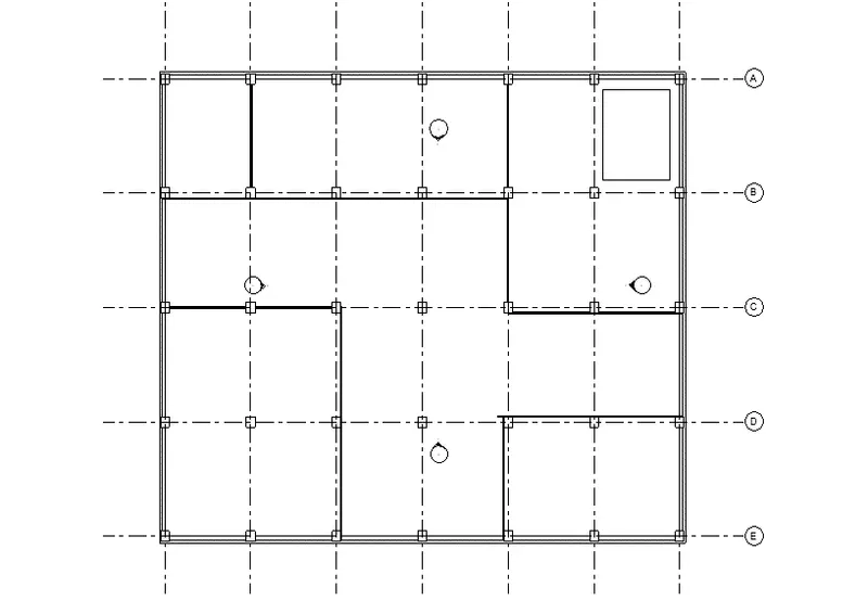
First we need to open the architectural template then select the external walls.
By selecting the wall pattern and
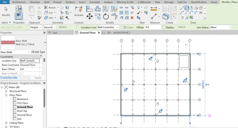
Now click on the wall then select differnt pattern for the interior and then create a wall.
by placing them as per the requirement.
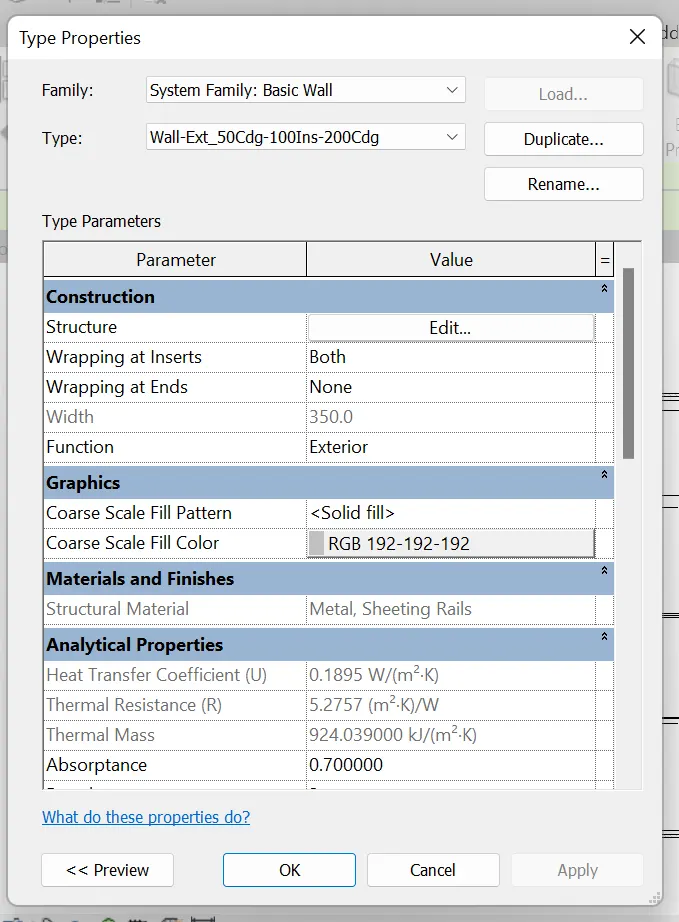
To edit the wall type and the finish we need to go to the properties tab and click on edit type
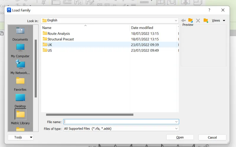
To add the components we need to go to architecture tab and then click on the components icon and then click on the load family.
Then select the components and the place them in the in the model appropriately as per the requirement.
dividing in to the category add the every single item into the file as the details i am showing one of the component how to get them and rest of items i would add them and place into the project.
Now i choose furniture in the family and ichoose the seating.
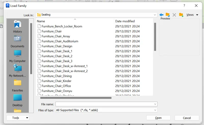
Now click on open and the place the component as per the requirement.
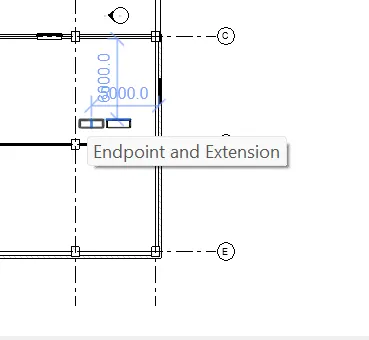
Now after the elements it looks like this.
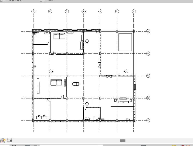
To add the lightings in the room we need to create 3D view of the room.
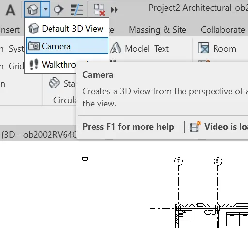
Now to create the the room view then go to the components.
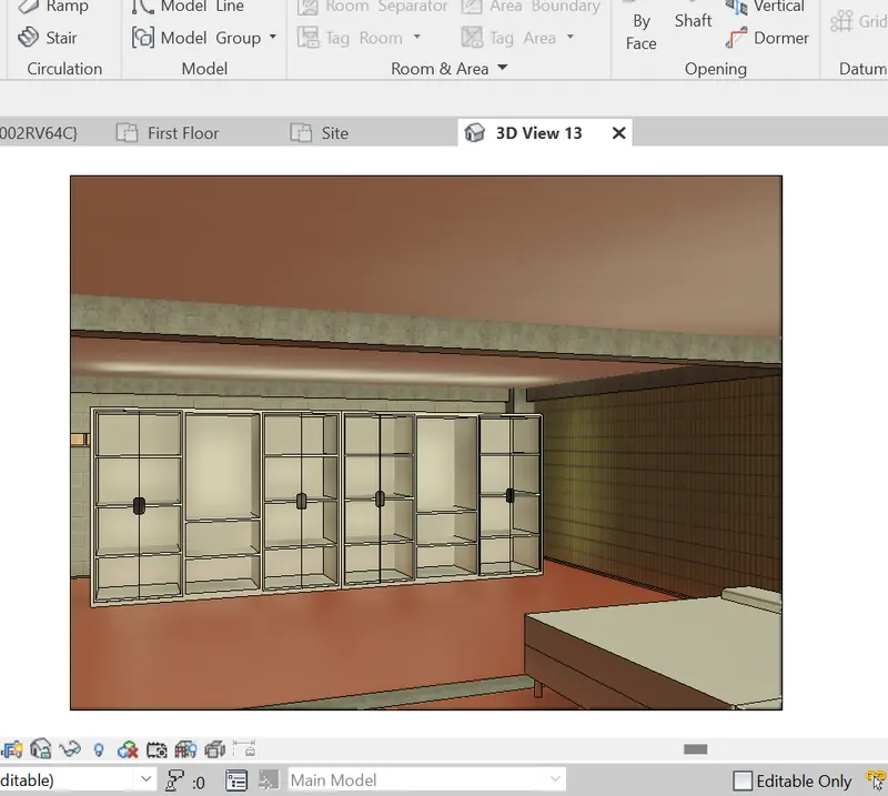
Now click on the components go to families and the lighting family then click on the architecture. now select the type of component we need then click on OK.
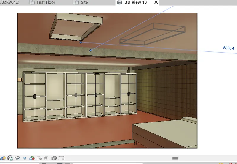
Now add the lights for all the room with the same process.
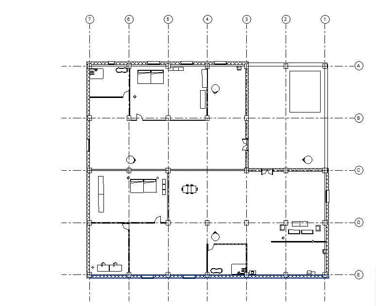
Result:
As a result we have a we now have an architectural model.
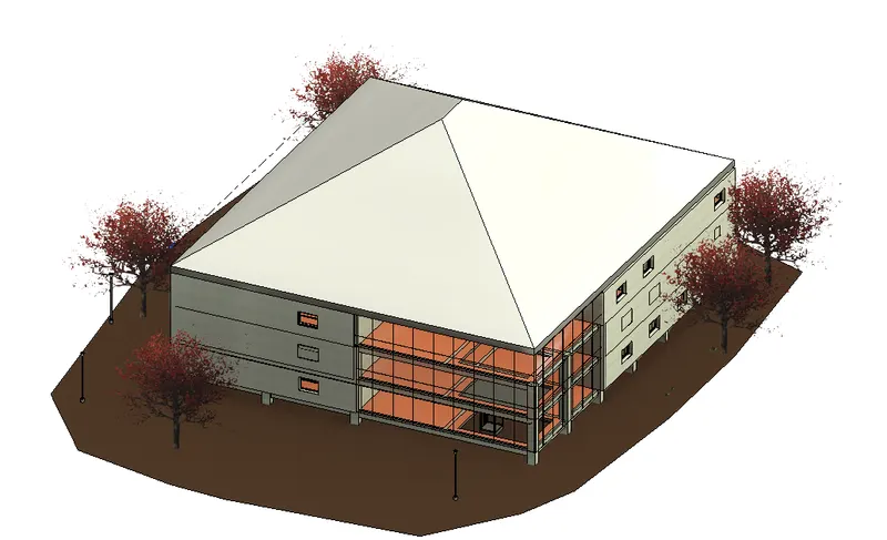
5) Provide a set of drawings in an architectural and structural model to list the following details with categories and appropriate sheet templates included
a. Floor Plans with Annotations
b. Elevations
c. Sections.
Aim:
To provide a set of drawing from the architectural and the structural model.
Introduction:
By Providing the drawings from the design help to get the permission and create a construction documentation.
Procedure:
first open the architectural template and open the ground floor and then go to the view tab and we can see the plan icon on the screen.
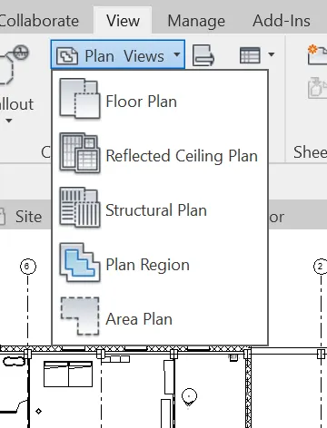
now select the floor plan and select the level and click on ok to create floor plan automatically.
we can see the plan has been added to the property browser.
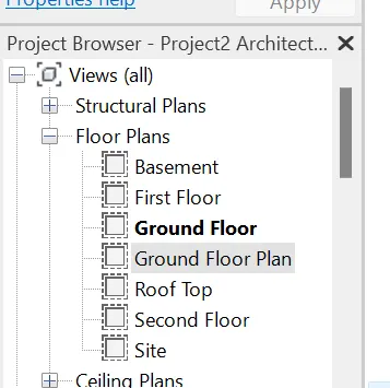
as same way create next level plans.
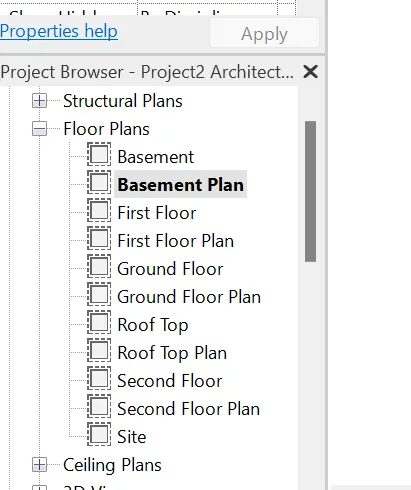
Now to give annotations to the plan click on the plan to open the go to annotation tab.
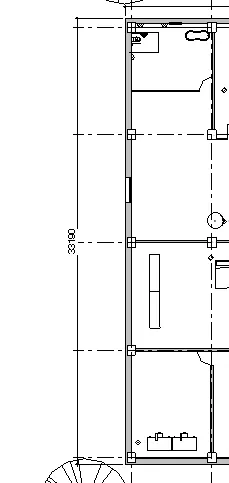
As the same way go to all the dimensions and give dimensions.
Too create section we need to view tab again we can see the section icon click on that to select.
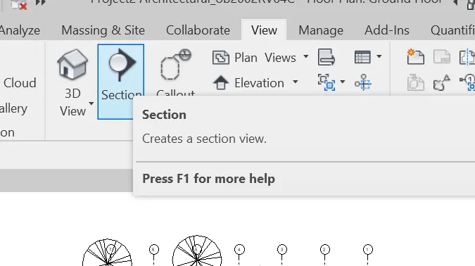
now select the section and click on the screen.
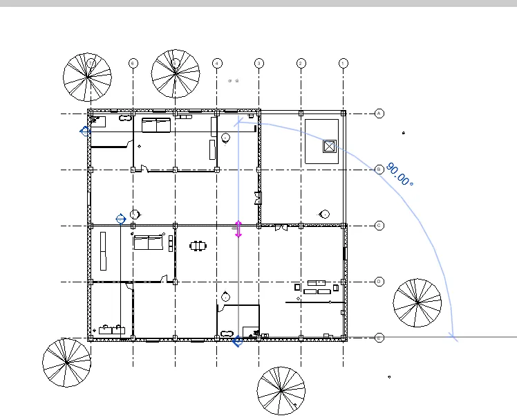
As this section has been created for now.
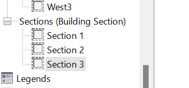
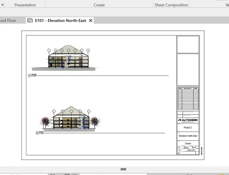
As we know elevation are alreay in the property tab.
Now to create a sheet go to view tab then click on the sheet.
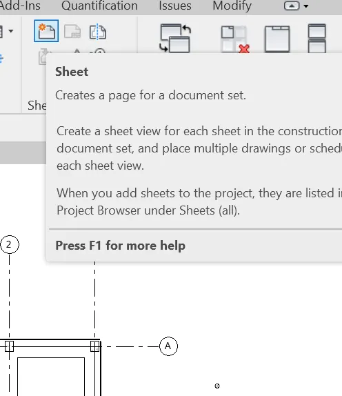
a sheet will be geneated like this. niw we can change the parameters of the sheet and add the drawings.
To chage the parameters we need to doubpe click on the sheet.
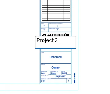
Now to add the floor plan wen need to drag the drawing into the sheet and click on the sheet.
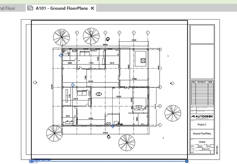
After adding the section.

Elevation
Result:
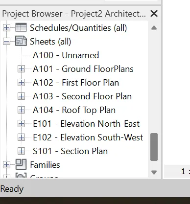
As a result we now have the drawing sheets.
6) Using the Rendering settings, Render images of the 3D model produced and include the rendered images to the drawing sheets
a. Rendering from interior rooms
b. Rendering from out showing topographic features
c. Rendering through structural framing
Aim:
To use the rendering setting and add the 3D models to the sheets.
Introduction:
By providing the clear presentation clients and the works we can show the details of the project.
Procedure:
First we need to have the 3D camara view of the rooms so that we can create names as we already have the vues i will direstly continue to the renderind.
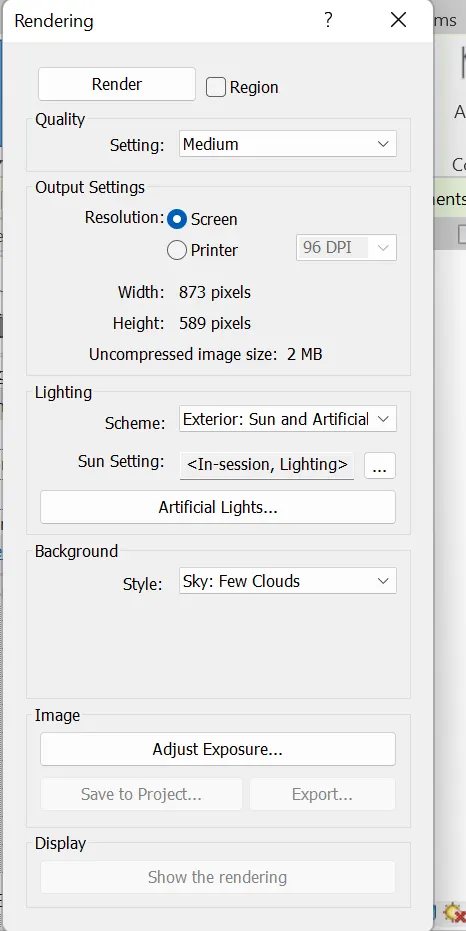
now go to view tab and click on the render icon.
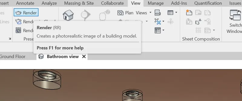
Then it will show you the new tab asking for the kind of rendering you need.
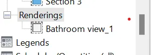
Once the rendering is done we can see them in the properties tab.
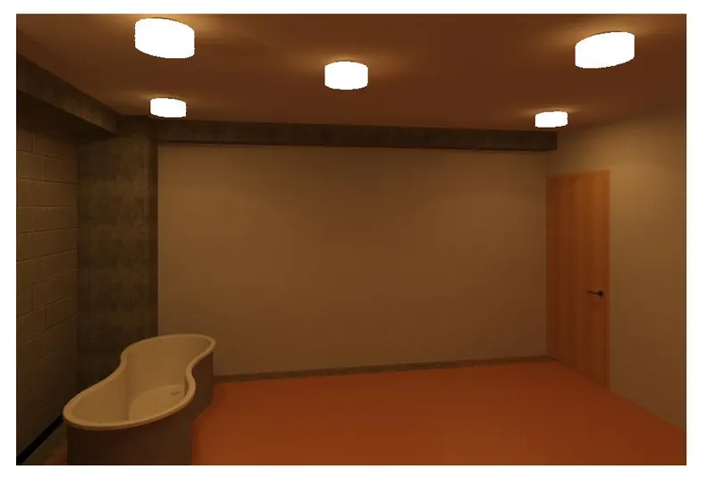
as the same process create some rooms.
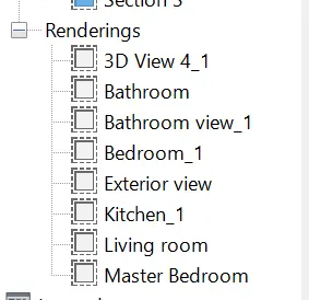
Now to add the create the sheets to the renders.
go to view tab click on the sheet as we know.
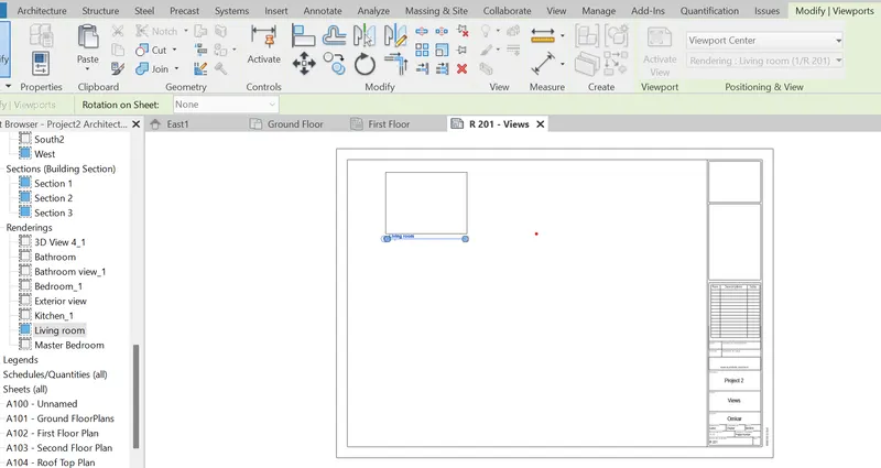
Now click on the screen and give the scale to the view.
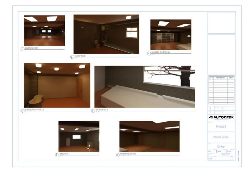
Result:
As a result we now have the all the sheets in the renfering plans section elevations.
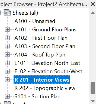
7) Print the set of drawing sheets created and submit the drawings from the architecture and structure model?
Aim:
To print the sheets from the architectural and the structural model.
Introduction:
By printing and submitting the sheets give you an perfect submition of the project.
Procedure:
First we need to open the sheets we have created.
We need to go to the files and then go to the file then click on the print.
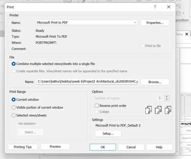
Then click on the pronter to select and click on the setting for the paper settings.
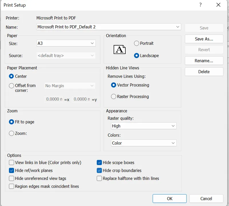
Now click on OK to print the project and to save the file.
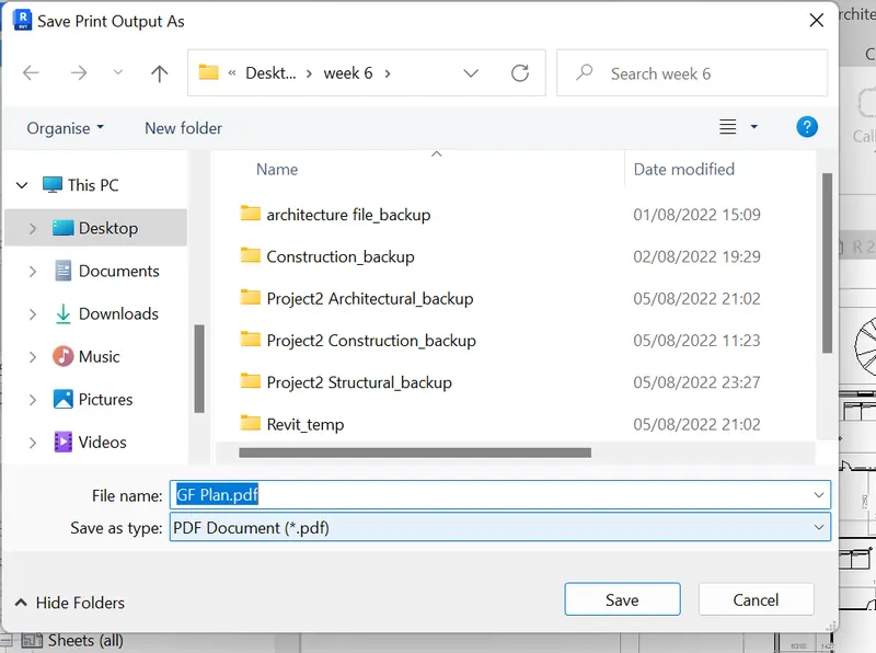
As a result we can see the copy.
Result:
As a result we now can see the print of the plan