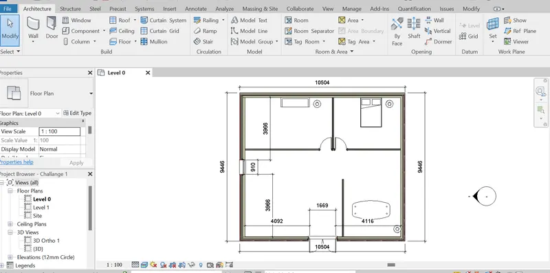
Creating Levels, Grids, Layout and model elements for a residential unit using REVIT
1) What is BIM? Summarize the features of BIM and benefits of using BIM over 2D CAD tools?
AIM:- To identify what is BIM and its features and benifits of BIM over over 2D CAD.
Procedure:
BIM is a process of creating and managing the project lifecycle. This is a visual representation of the physical and functional characterstics.
Features of BIM are
- Easy access to information by providing every minute element of the project.
- BIM provide two more elents with respect to Length,Breath,Depth and Time and Cost.
- Comprehensive view of the project.
Benifits of BIM are
- Complete Representation.
- Real-time collabration.
- Time Constraint.
- Resource tracking.
2) Understand the concept of Categories, Families, Elements, Instances in Revit. Go to Insert Tab, choose a category. Pick a family and element. Understand the instances and insert it to Revit model?
Aim:- To understand the concept of categories,families, elements,instance and then insert and element or insatance in revit model.
Procedure:-
Categories controll the organisation, visability and scheduling option within the project
Family is a group of 2D or 3D Building that serves the parametrical, physical and documentational elements of the project. then Type comes under the family categorie.
Instances is an indivigual representation of the type in the project whicah has its unique parametrics.
Inserting an elements from the family in revit:
First wee nee to go to the architecture tab. in that click on any thing like a door, window. here i select the door then the window chages like this.
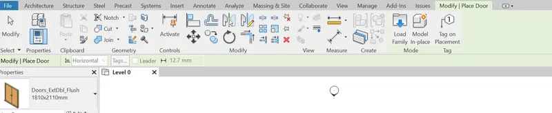
Then we need to click on the load family on the right top. Then a new window will be pooped up.
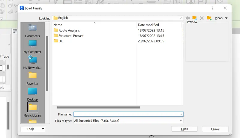
Then click on the UK so that you can see the categories. In that we can select the doors family by double clicking on it.
Then you can see the different instances and categories then go to external door the select any one of the door as per your wish.Then wee need to go in to the. then click on open
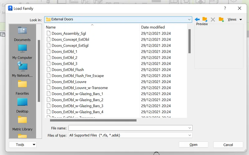
Once we clicked on open we csn see a door element appear on screen we can place as per your rquirement by clicking at the place like this.
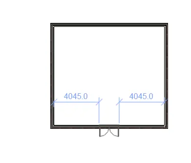
Now we inseret instances.
First select the window file now. Then click on the load family on the right top. We can see the categories then we can select the windows in the categories.
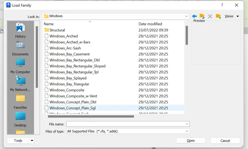
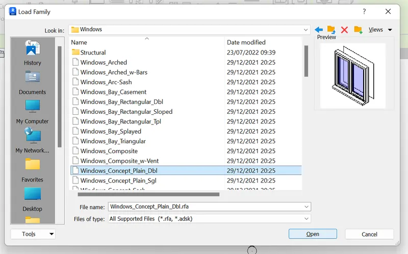
Then we can see the instances in the files then select one of then and open the file. once we click on the one of the file we can see that the object o hte right how it looks like.
Then we can see that on revit file then place as we wish to place on the revit.
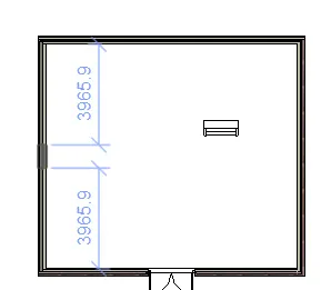
Result:-
As a result we can see that in our revit file we got a door and window. which are element and the instance.
3) Setting up a Project – Open a project file with architectural template. Save the file with appropriate name. Set up the project units to Imperial / Metric based on your convenience of modelling. Complete the project information under Manage tab. Set up the maximum backups for project file to 3?
Aim:- To set a new project with an architecture template and change the units for the projects and setting a 3 backup files.
Intoducation:- In this we can start up our new project by setting our units and saving the backup file in the revit 2023. How all this backup and the project file can bee palaced are added will be seen in this.
Procedure:-
First we need to open the revit and then we need to open the Architecture file which we saved then double click to open.
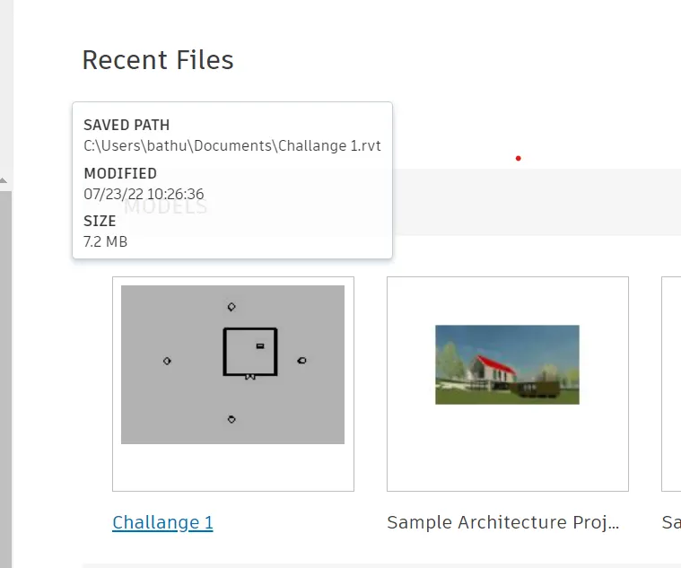
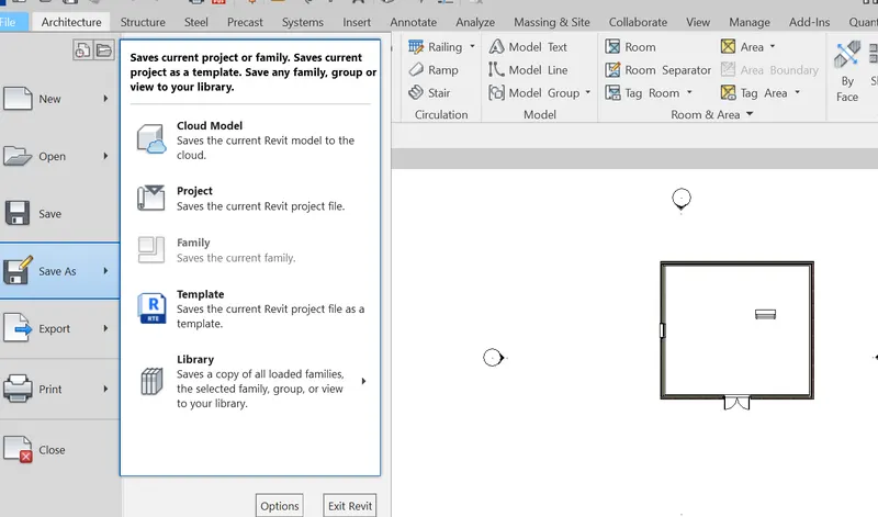
once we clicked on that it will open like then then we need to click on the file bar then click on the save as to give a name and change the project.
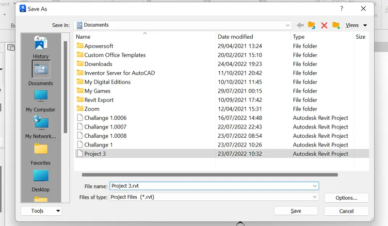
Then give a name to the file and the click on the save.
Next thing we need to do is to change the project units. To change the project units we need to click on the manage bar then we need then the bar changes.

Now click on the project units icon to change the project units.
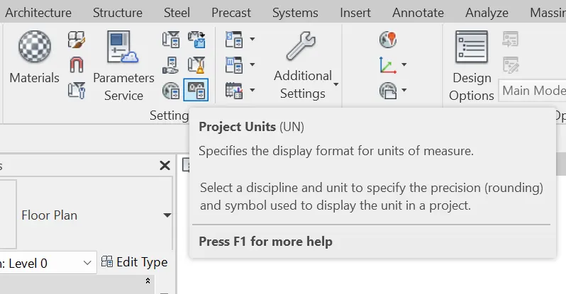
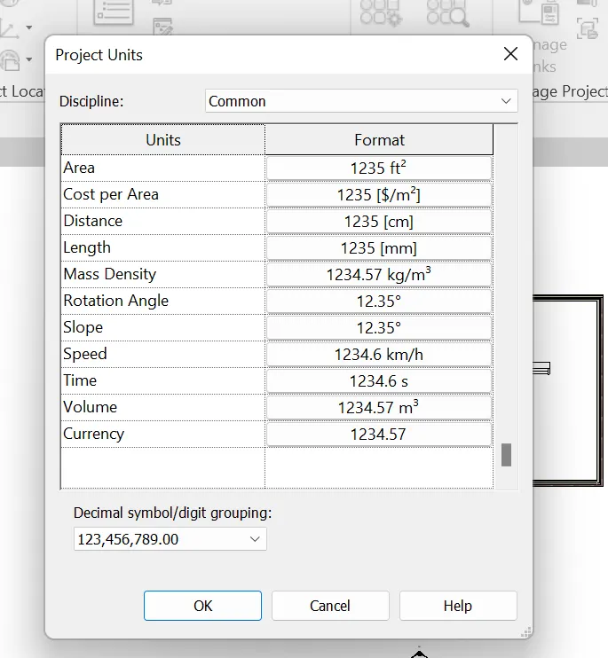
once we click on the project units we can see the changes. we can set the units as we wish by metric/imperial.
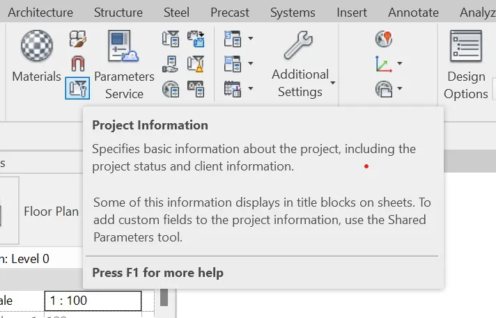
Then we need to click on the project information to change all the project details by clicking on the project information icon in the manage bar.
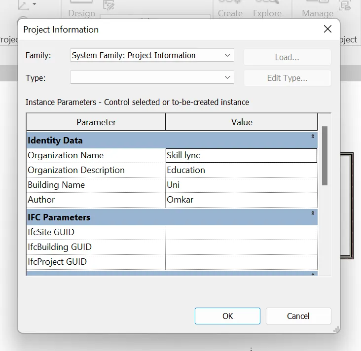
Then a new tab will appear on the screen like this with the perticualar project informantionn we nee to fill the details like this approprait informantion on the screen. Then click on OK to save the project information.
Now we are saving the file entering the maximum backups.
first we need to go to files then click on save as the we can see the icon as options beside the name of the project.
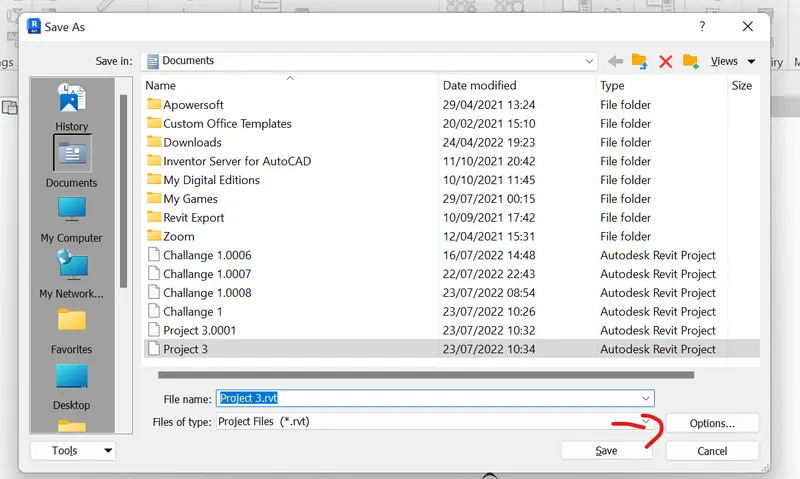
click on the option we can see that ask for how many now of bacups we wants to save the file as.
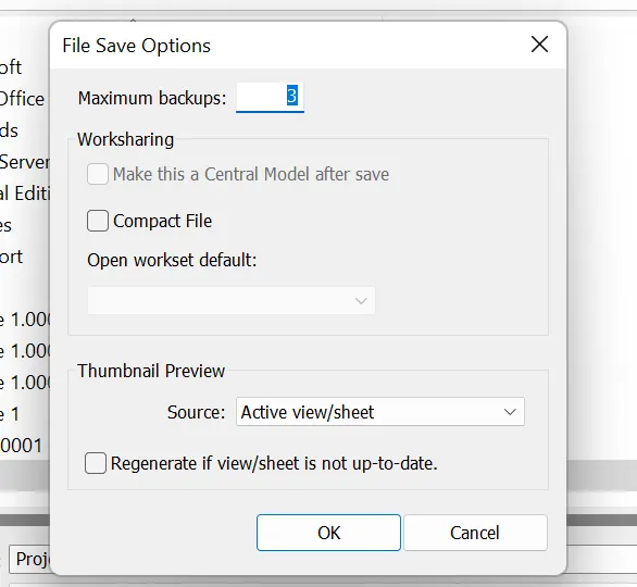
Give the no of backup then click on ok. then click on save the project to save the file.

Result:-
As an end result we have a back up file with the approprait name and information.
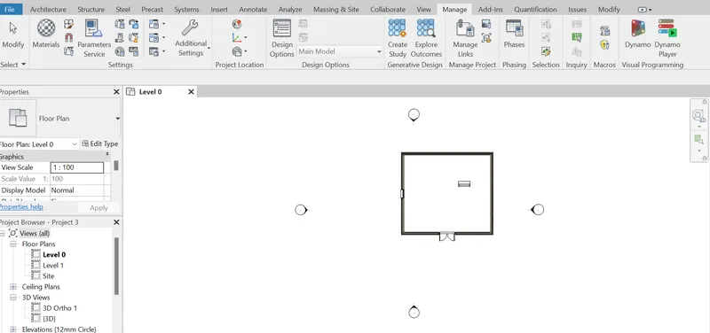
4) Understand the concept of Levels and Grids. Follow the naming and conventions. Create the following Levels: ( Convert to metric equivalents if metric is your units)
Ground Floor @ 0’
First Floor @ 10’
Second Floor @ 20’
Roof @ 30’
Grids Transverse Grids A, B,C,D, E @ 10’ spacing
Longitudinal Grids from 1 to 10 @ 20’ spacing.
Aim:- To understand the cocepet and adding the levels and grids to the drawing.
Introduction:- In this we will understand the concept we will be learning the grids and the levels to the project. This way we can underatand their uses and adding to project.
Procedure:-
First we need to add the levels to the project then we need to go to the elevation view to see weather we are adding the levels to project . the elevation view can be seen under the propeties tab.
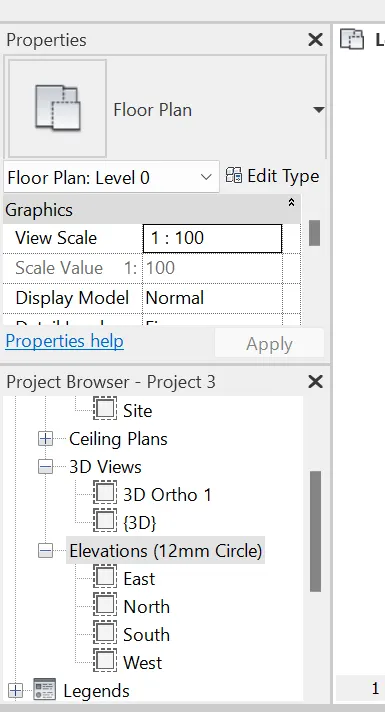
Click on the any side of the view to see the levels. Now we can see the view of the east.
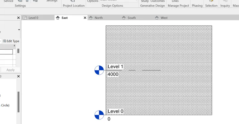
Now we need to go to architecture tab where we can see level option on the top right of the tab.

Then click on it we can now see the new icons wee need to select the pick line and then give the off set distance for the levels. then click enter to save the offset then click on the existing top level to give nect level now we can see it inbelow how it appears.
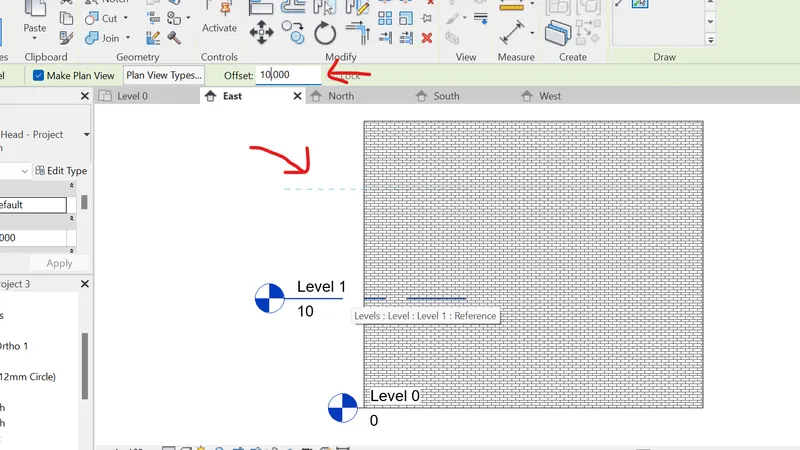
Once we click on that it will show us the level noe like this.
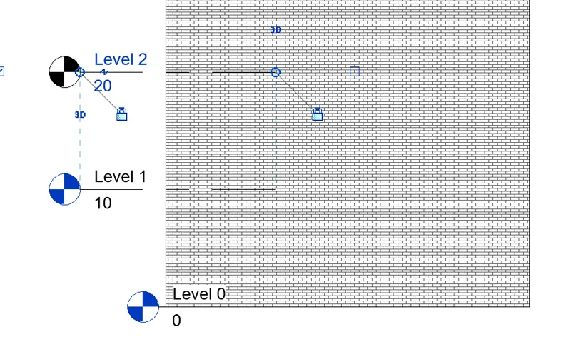
As the same way click on the to level to create next level becouse our offset are same for each level.
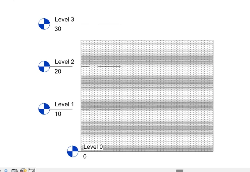
Now we can rename levels by double clicking on them and change the name.
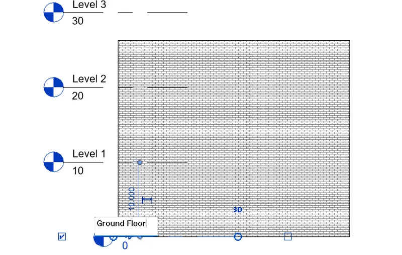
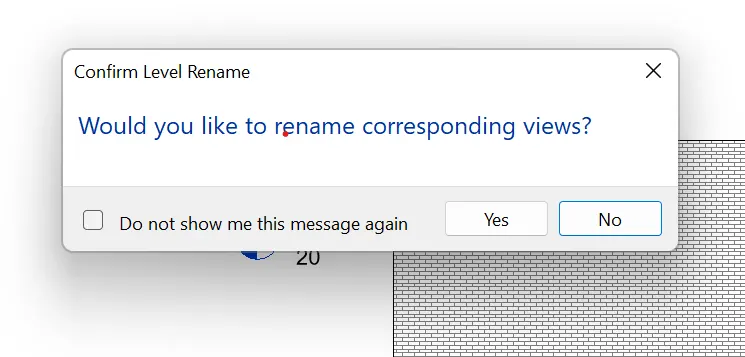
Then click yes enter after giving the name.
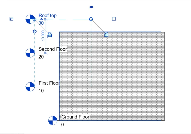
As same way change all the names for the levels.
Now to create the grids we need to go the archtecture tab in the right top we can see the grid option below the levels then click on it. then the bar changes like this now select.
as shownen in the picture click one by one to set an first off set at 0 by selecting line in modify bar.
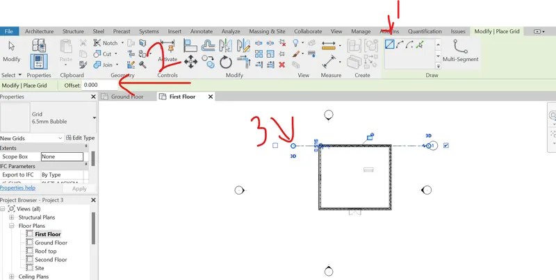
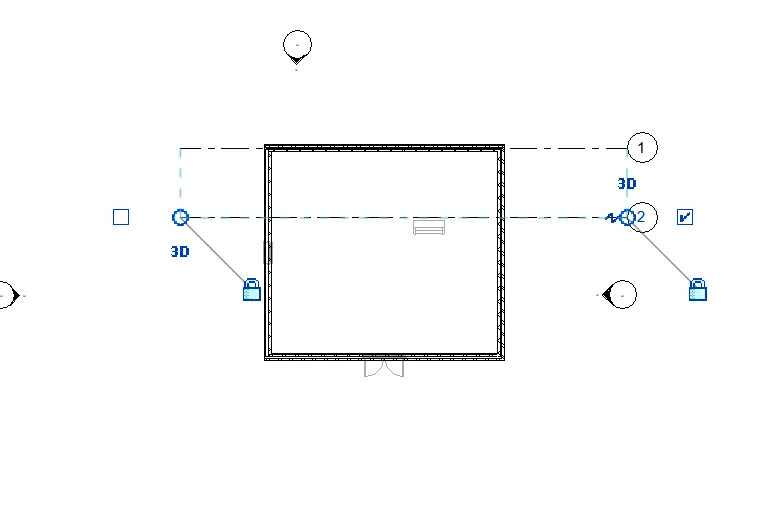
Next select the Pick line in the top right adn give the off set distance as 10. Then click on the first grid line now we can see the other grid line on the screen.
.
Then we give all other grid as per we need them.
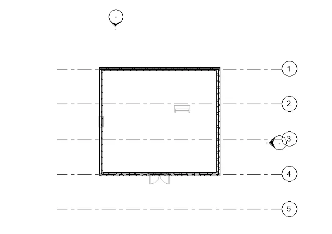
To give name to grid line double click on it and then change the name.
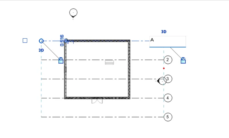
then click enter to change the name. As the same way change all other names.
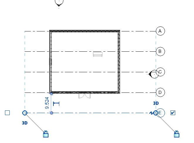
Now we set the grid lines longitudinal. go to the architecture then click on the grid select linr then select the first grid line position.
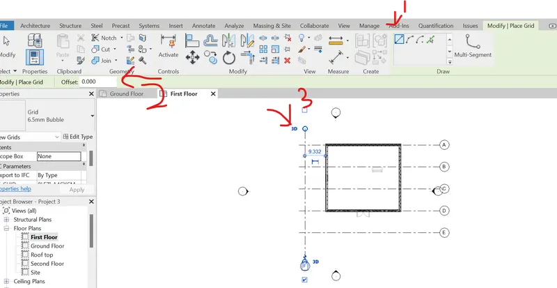
Now gove the offset distance as 20 as we know the distance then click on enter and click on the first line. then the next grid line will appear then select other.
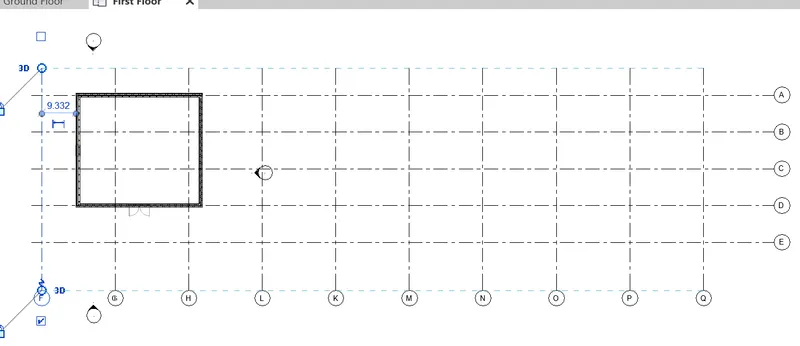
Then double click on the line to change the name of the line.
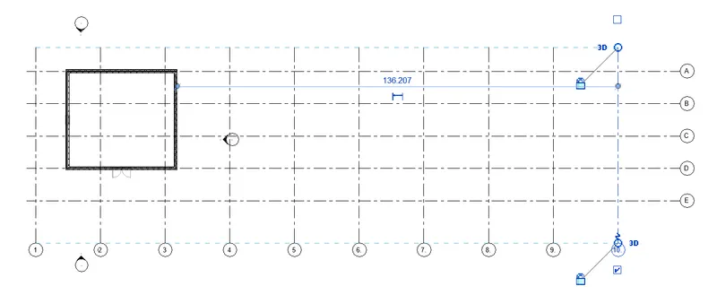
Result:-
As the result we can know the cocept of grid lines and we have seen how it places in our project.
5) 3D modelling of residential unit – From looking at your house / or a place you aspire. Create a conceptual layout of the residential unit. You can measure using a tape or
you can access your residential plan to create a similar layout?
Aim:- To create a conceptual layout.
Introduction:- To create and layout as per the imagination are the looking at the own place where we are staying. this is to identify the place to start a design.
Procedure:-
As we creating a conceptual layout we nee to open a new architectural file then we can click on the archiceture tab.
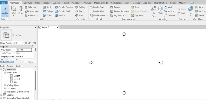
Then click on the wall to give the layout border.
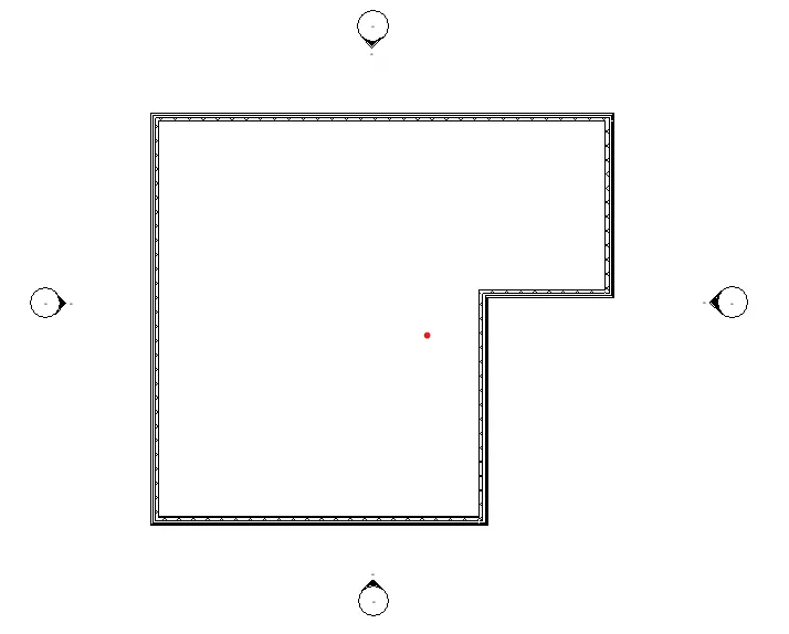
This is the cocn ceptual layouy of the residential area which i am staying.
Result:-
As a result we have a layout for our project. this layout is my residential area.
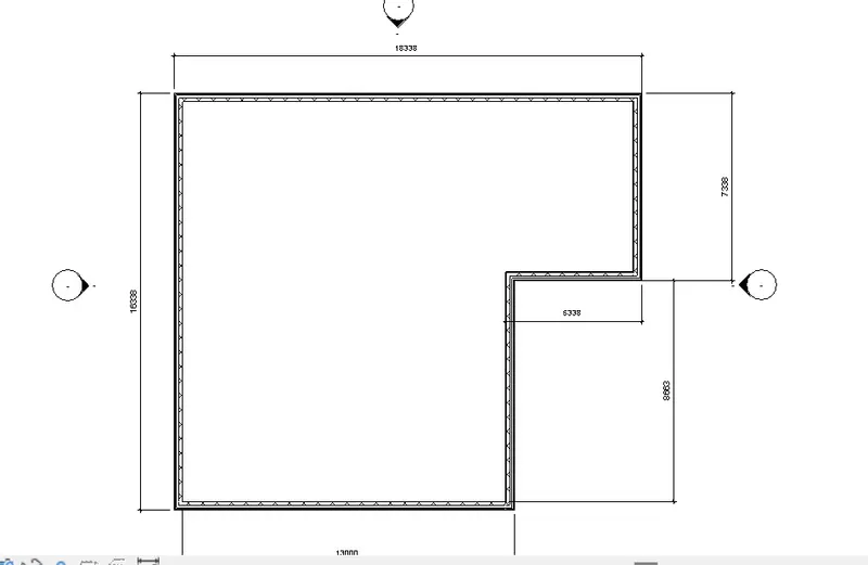
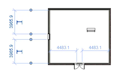
6) In the layout created draft the level of details you are planning to include – Dimensions of room, components you plan to add in the residential unit?
Aim:- To give an dimension to room and the components placed in our residential unit.
Intoduction:-
In this part we are going to see hiw tio we are adding the dimensionds to the revit model. This usually helps to check the positioning of the components and the area we are using.
Procedure:-
First we need to open our revit file by click on the open button the project. Then we need to go to the annotation tab . w then all the icons chage on the bar then click on the linear .

Once after we clicked on the linear then click on the inside edge of the room area as the both sides of the side.
once after we clicked on the line we can see the dimension appear on the screen like this.
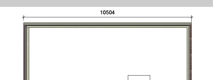
Now i am providing the dimensions for all the components wich i have given to the project by clicking either sides of the lines.
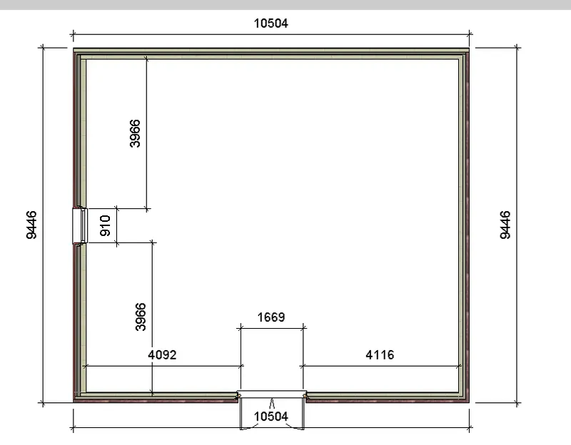
Result:-
As an end result we got the project with the exact dimension of each room and the component places in the project.
7) Identify the residential model elements such as Door, Windows, Tables, Chair, Couch, Bed, Lamps from the library and insert them to the model . Save the project for use for Assignment 3 ?
Aim:- TO insert the bed, chair, lamp,coach and table from the library and load them to the project.
Introduction:- In this section we are going to give more detailing to the project by inserting the elements to the project by loading them from the family.
Procedure:-
First we need to open the file then we need to open architecture tab then click on the components . AS the icons changes in the bar then click on the load fmaily on the roght top of the icons.
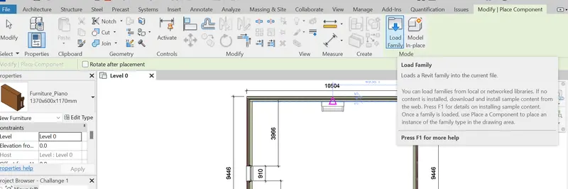
Then click on the Uk file.
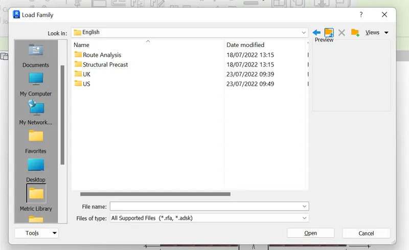
Then click on the Furnitur and click on the bed.
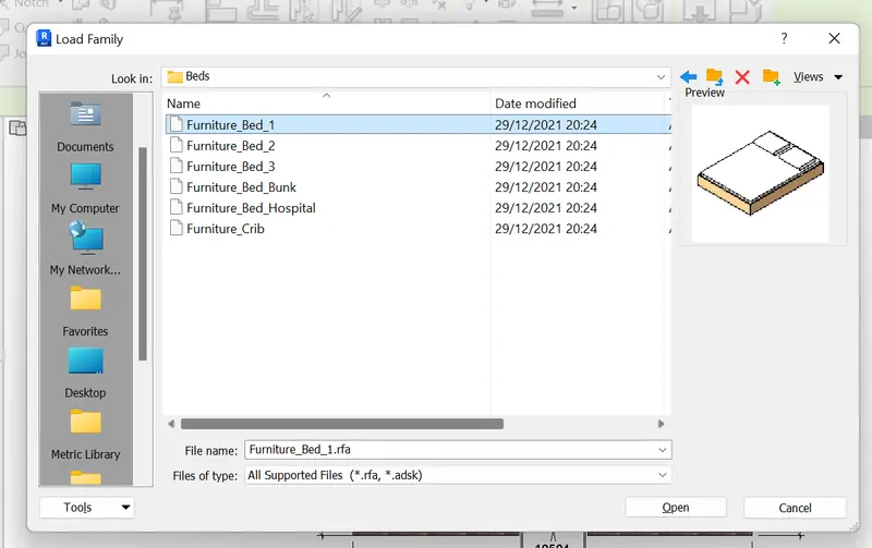
Then click on the open and then place them in the project file any where as you wish and clik on the screen to place the item.
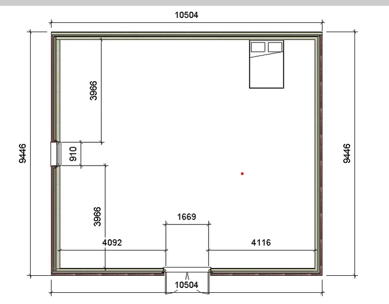
Now go back in to the categories and go to table to palce lamp in the project file.
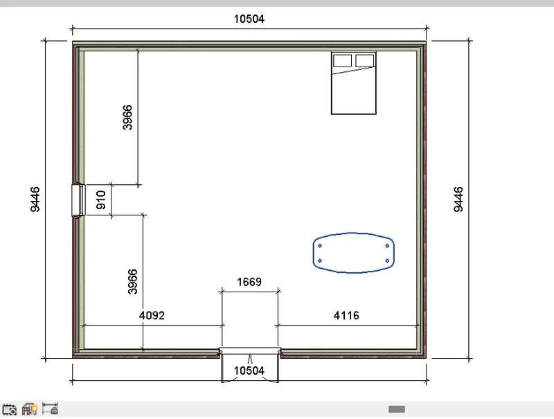
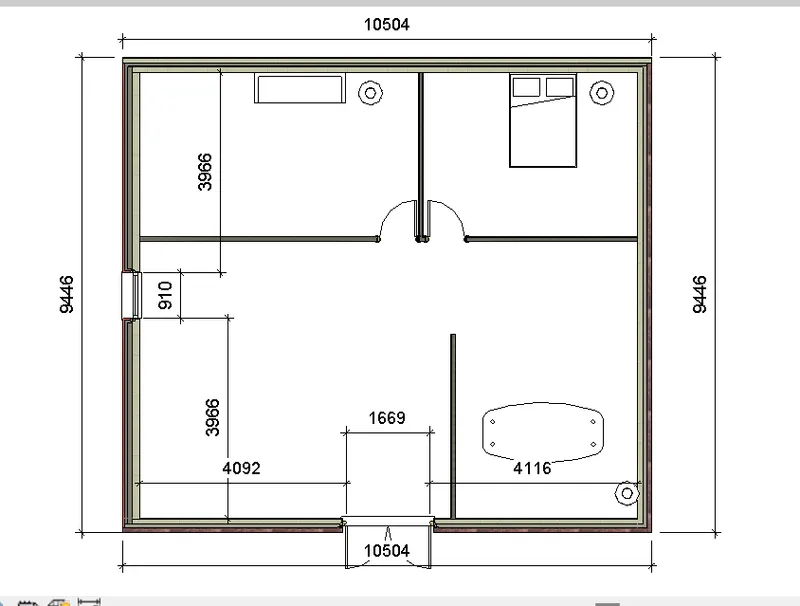
Now we are placing the rest of the components like lamp, chair, cauch.
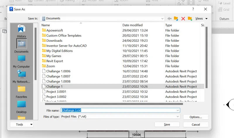
Now click on the save as then give approprait name to save the file for the next assairment.
Then click on save to save the file.
Result:-
AS an end result we have our project with the all the elements we need to be in an residential house. this gives our detailing.