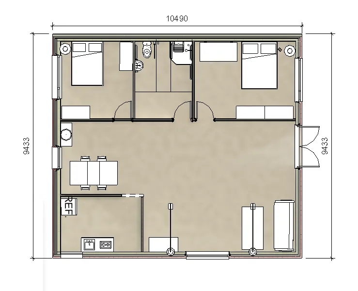
Creating Walls, Partition walls and Floors for a residential layout using REVIT
1) Use the project file created from Week 2. Use it for this assignment. Based on your layout from week 2, using floor tool under architecture tab and select the floor with appropriate material and thickness using the property browser create a layout in the Ground floor Level. Align the floor plan with grids created from week 2?
Aim:-
To Create a floor in ground floor level with appropriate materia and thikness by using propoerty browser.
Introduction:-
In this we will learn how to place a floor with approperate matrials and the thinkness with respect to the layout.
Procedure:-
First we need to open the project file 2. In the architecture tab we can see the icon of the floor click on it.
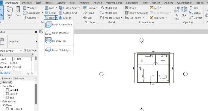
Then click on the architecture floor we can see ribbon tab change immediately. Then on the right corner click on line icon.
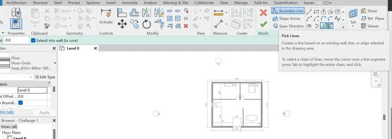
Now select the boundaries of the wall we can see a pinkn border that we selected the corners.
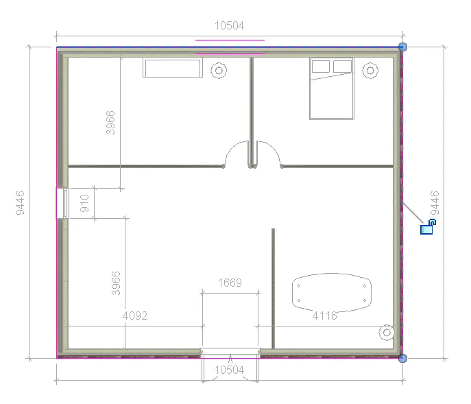
then click on the tick mark on top. then the floor is added to the file to check weather it is added or not go to the 3D view. by clicking the house icon on to of the riddon bar.
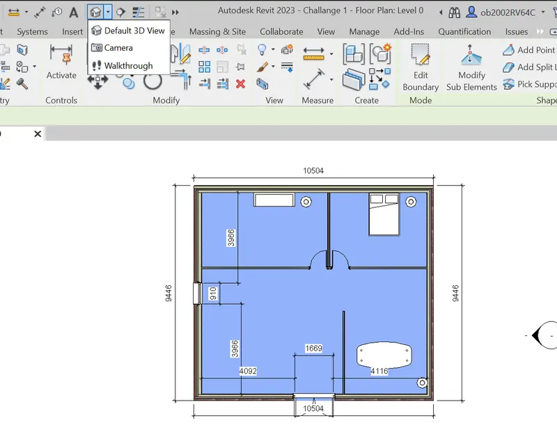
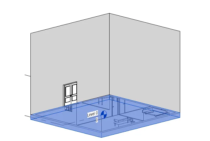
Now we can see the floor has been added to the plan.
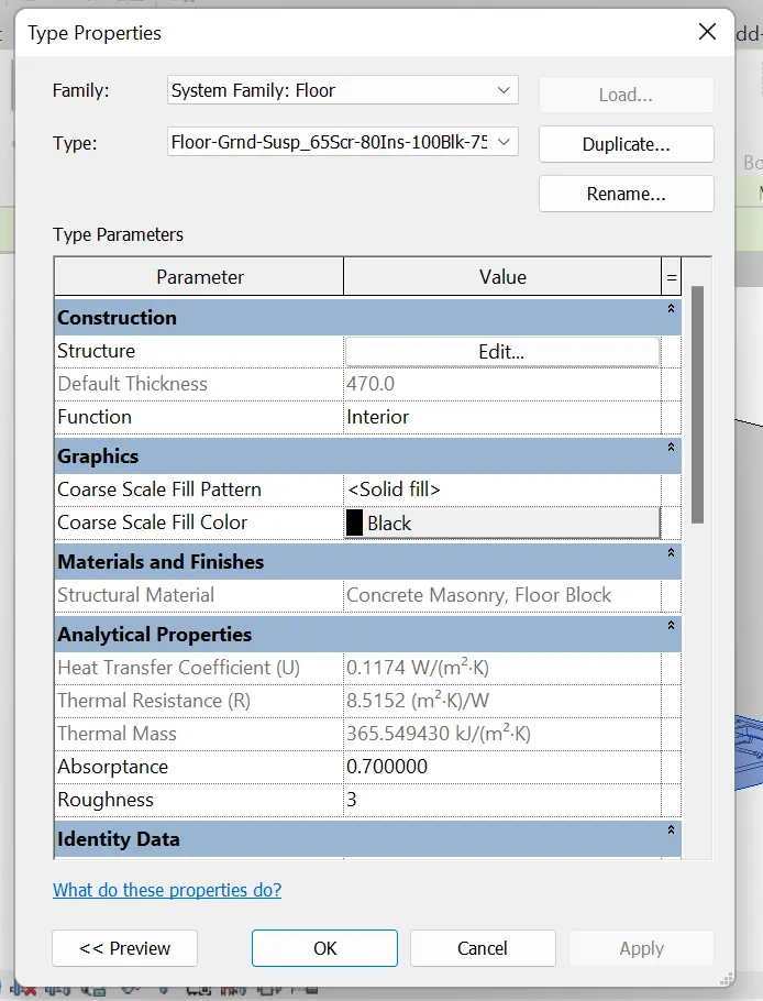
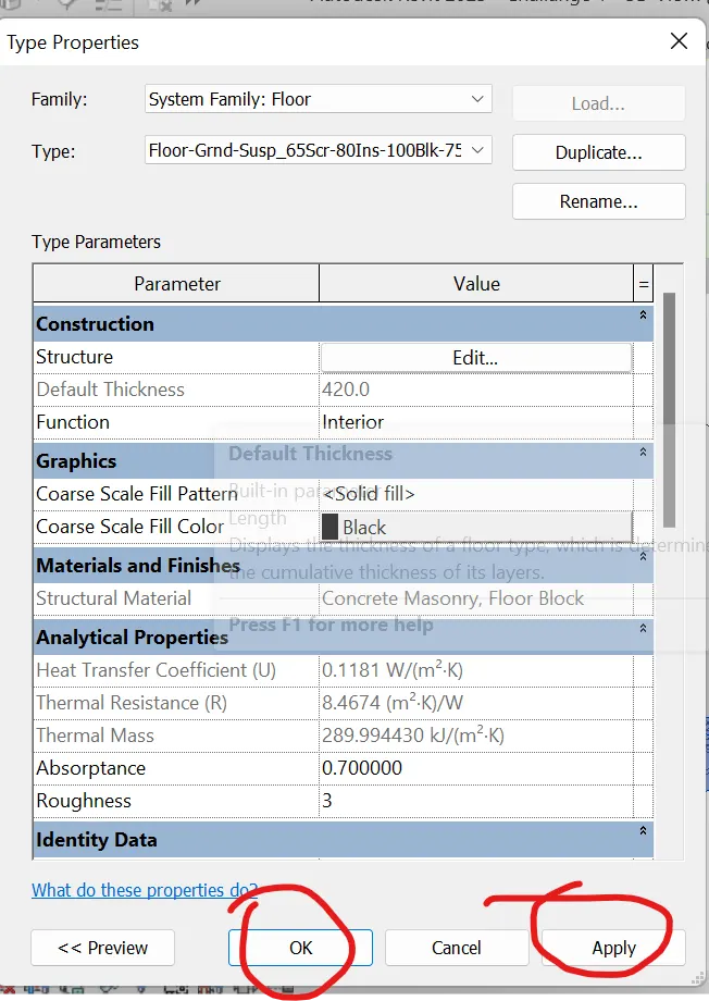
To change the properties of the floor click on the edit in the properties bar. we can see new tab opened.
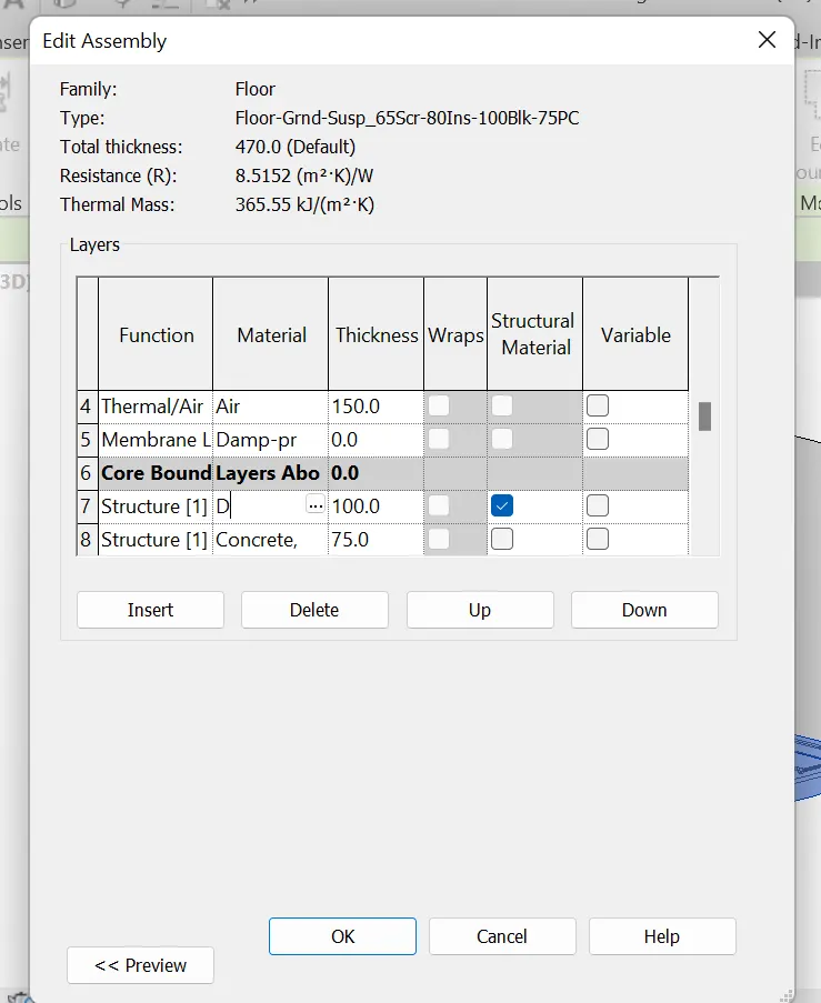
Beside the structure we can see the edit open click on it. new tab opens like this.
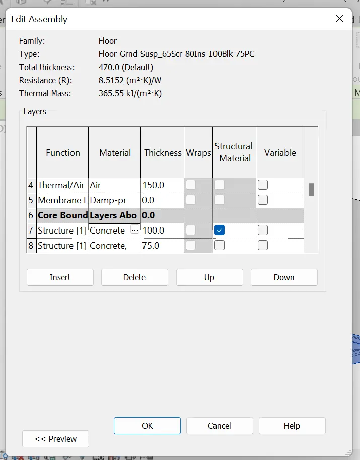
Beside concrete there are three dots click on it. new material tabs will be opened.
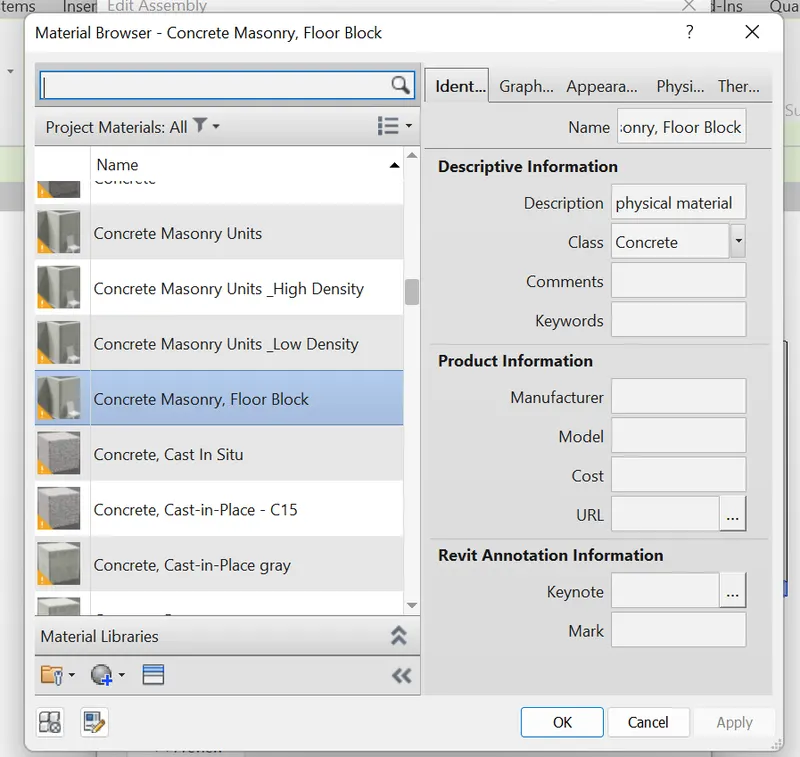
Now select an appropraite material then click on ok. Now give thickness to the material.
Then click on apply and then click on Ok.
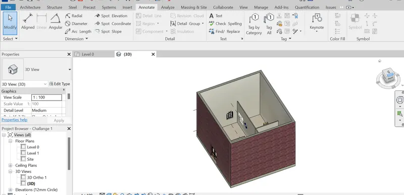
Result:-
As an end result we can see the that a floor is apply to the project with the approprait metrial and the thickness.
2) Add walls based on the floor layout. Pick lines or use the draw tool to modify the boundary of walls. Use the property browser to select appropriate material and thickness for walls. After creating the walls verify using the property browser to see if the top and bottom of the walls are constrained?
Aim:-
To add an walls based on floor layout and to modeify the wall boundaries using pick line or draw tool. Then giving a materials approperiate materials and thickness.
Introduction:-
In this we willl use be using the architecture tab and create wall appropriate to the floor. Then give them there properties and the thickness.
Procedure:-
As we have using the previous project till now the wall we have created in the previous project.
Now for that wall we need to change the properties to the wall by clicking on the edit type option in the properties browser.
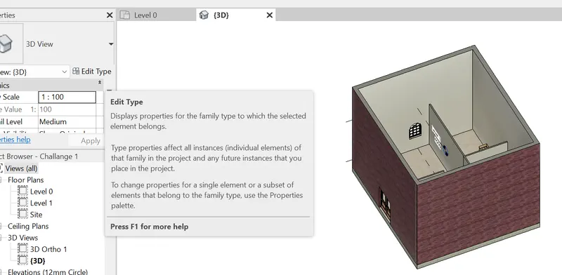
Then a new tab weill be opned then click on the edit beside the structure .
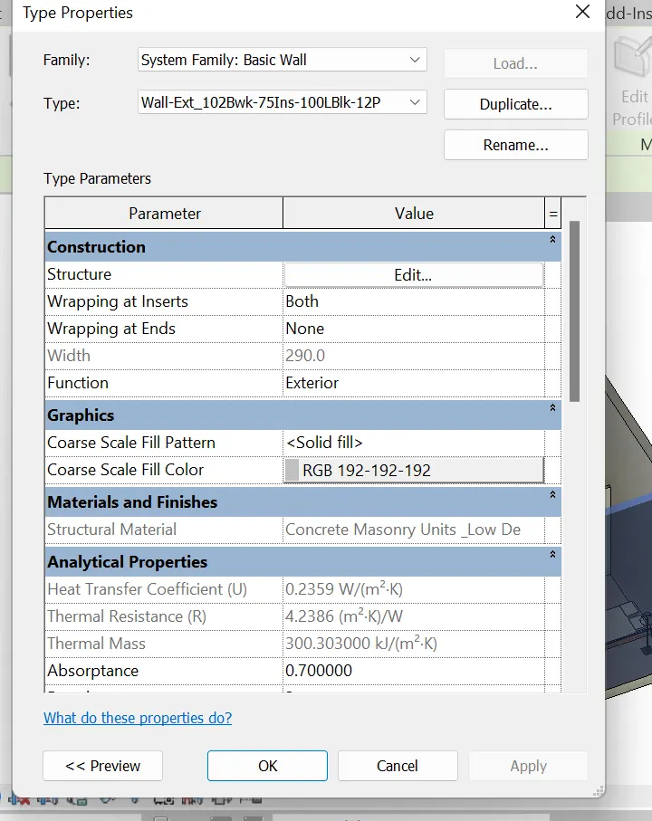
NOw click on the dots beside the brick in the materials. then select the approprait matrial as required.
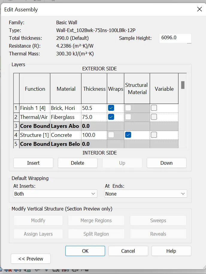
Then change the material thickness by clicking below the thickness beside the materials.
The click on ok. Now click on apply and then click on ok.
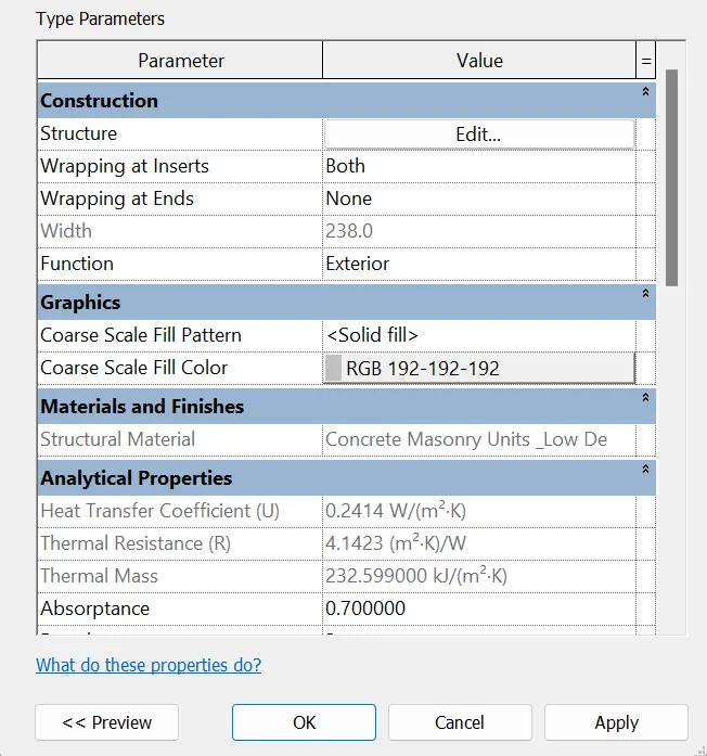
Result:-
As the end result we have now wall withe the appropriate materials and the thickness.
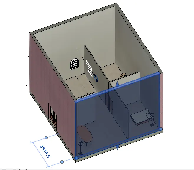
3) Copy the model elements ( wall, floor ) modelled to Ground Floor Level and paste it aligned to First Floor Level . Use modify tab to utilize copy and paste options to align elements to a different level ?
Aim:-
To copy the model elements from the ground floor level and to paste them in the first floor level by using the modify tab.
Introduction:-
In this we will learn the concept of addong the first floor by using the ,odiy tab and to capy and paste all the elements from the grong floor to the next. this could be the time saving process if the levels are with the same needs.
Procedure:-
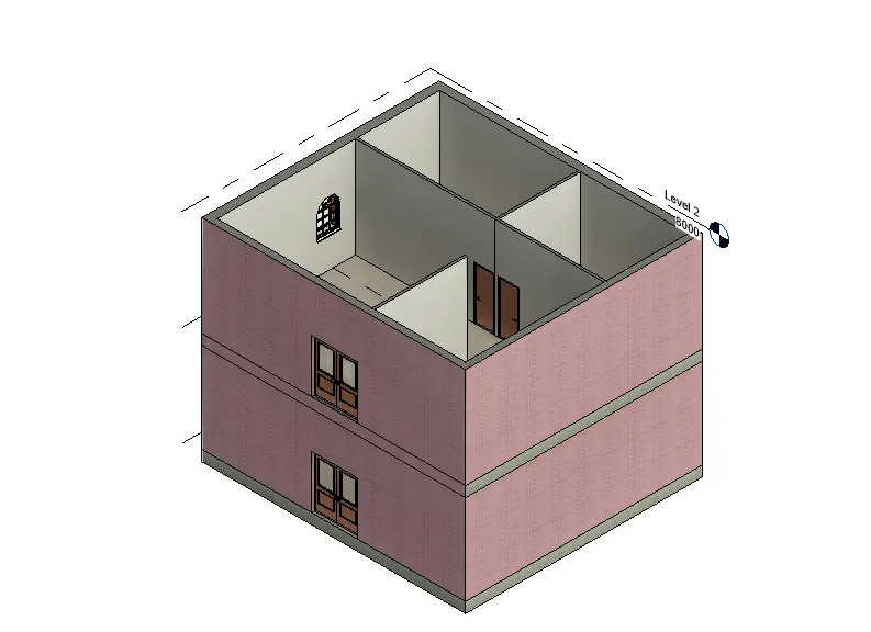
First we need to select all the elements in the ground floor by dragging and select.
Then immediately the ribbon tab has been will change.
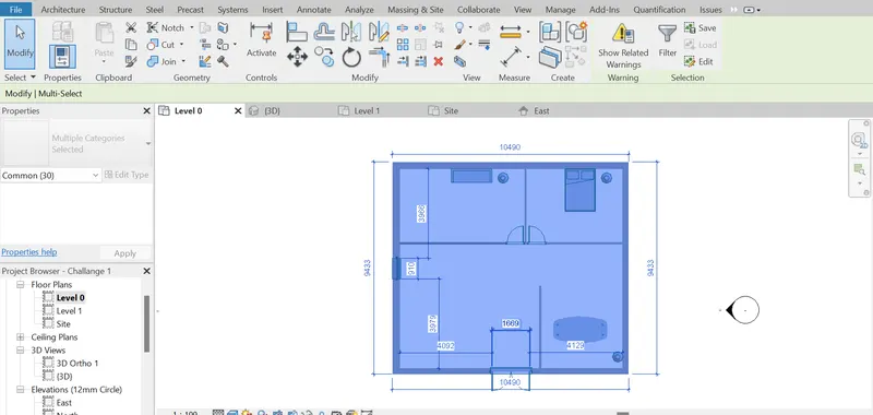
Now in the to we can see the copy to clipboard option on the top then click on that.
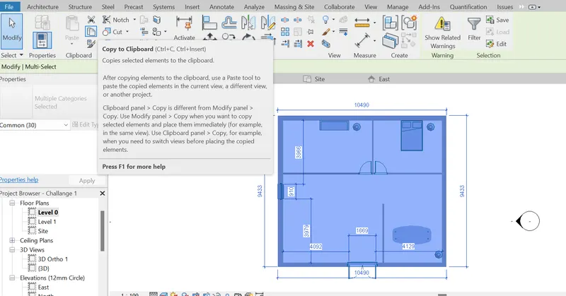
after we clicked on the copy the image will be copied then click on the paste icon.
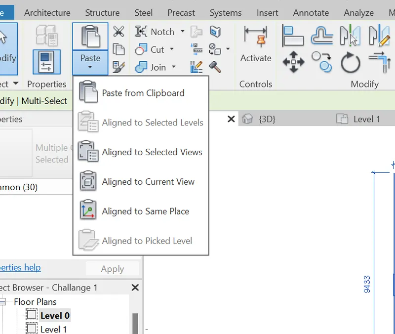
then click on the view by clicking on the level or open the level and click on the allign to the selected view.
RESULT:-
As an end result now we can see the floor has been added to the level same as the ground floor.
4) Use interior partition walls to create separate rooms within your residential unit. The model must include the following rooms
a. Living Room/ Drawing Room ( 15’ X 18’)
b. Dining Room (9’ X 11’)
c. Bed Room ( 9’ X 12’ and 15’ X 11’)
d. Rest Room ( 10’ X 12’ )
e. Kitchen (8’ X 10’)
The above are for examples. You can use them or use your measured entities to create your model based on your layout. You may include entry walkway, Patios or Guest
rooms based on your creativity and purpose of modeling. Convert units if you are using metric system.
Aim:-
To create an room with the approprait dimension in the appropriate place . give them the room tag and the area as given.
Intoduction:-
IN this will willl give the room as per the residential building and give them proper area and the tags.
Procedure:-
First we need to open the file and the click on the architecture tab. then click on the wall and select the internal wall with thickness.
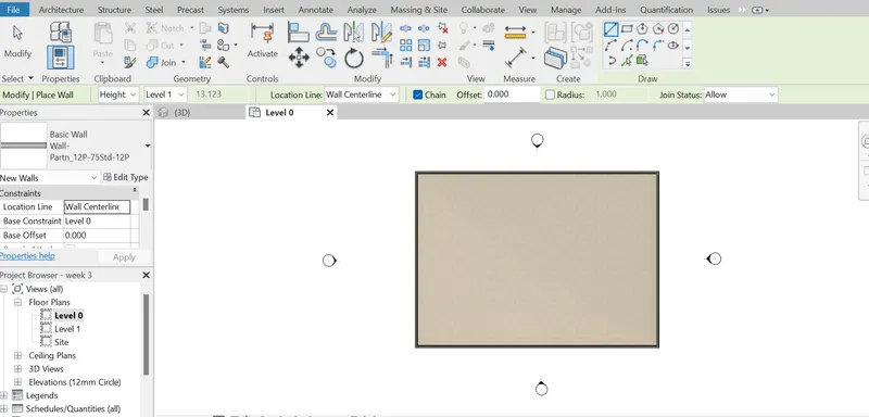
Once the ribbon tab is changed autometically then click on the rectangle on top right of the ribbon tab adn give the off sets of room.
here i selected the wall and then clicked on the line on top right and give off sets selected the point then the room will be in here.
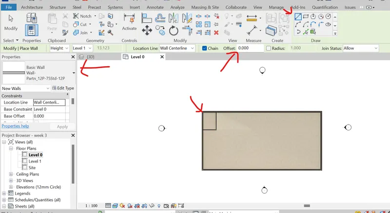
now as the same way click on the line and i have created a rest room with the wall and line options.
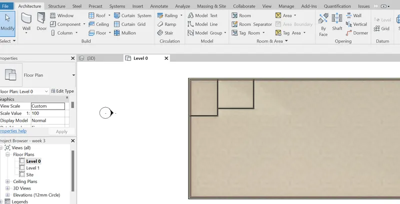
then we need to click on the wall again then select the line.
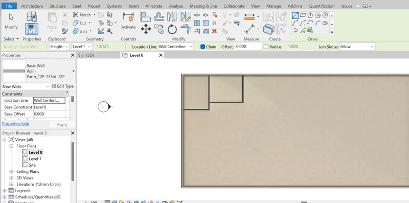
Now give the off sets to the plan of next bed room.create a room.
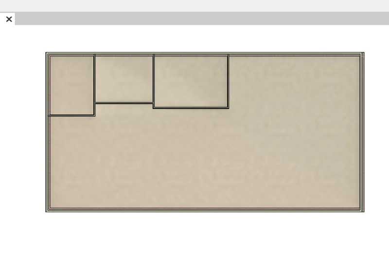
Now by selecting wall giving off sets for the kitchen.
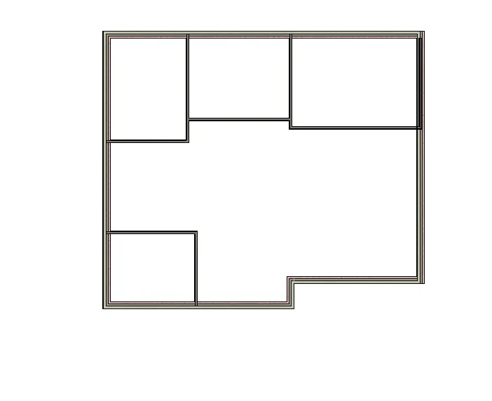
now use the room seperator to seperate living room and dining room
for that we need to click on the architechure tab. Then click on the top right on the ribbon bar.
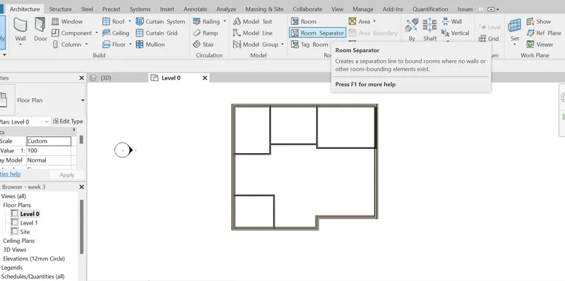
Then click on the start point and the end point as per the room requirements.
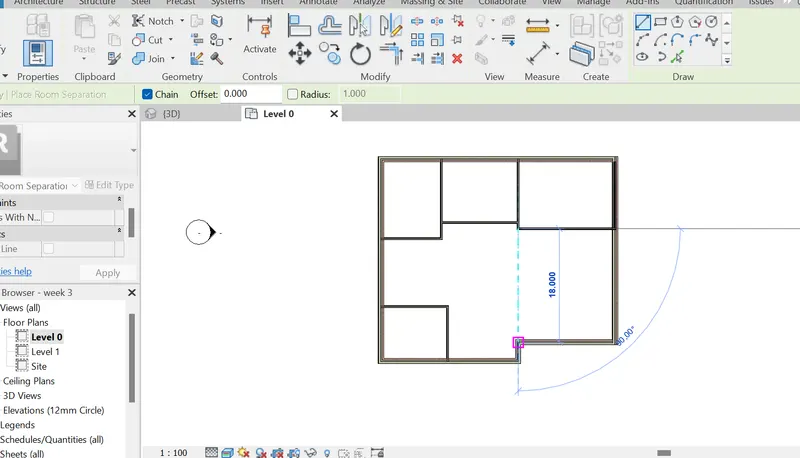
as same way i have seperated the dining room.
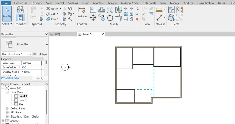
TO check ang to give an area to the rooms click on the annotation tab then the ribbon changes autoamtically.

Then select the linear and slect the corners of the room we can get the measurements.

As the same way select all the room to measurements to them.
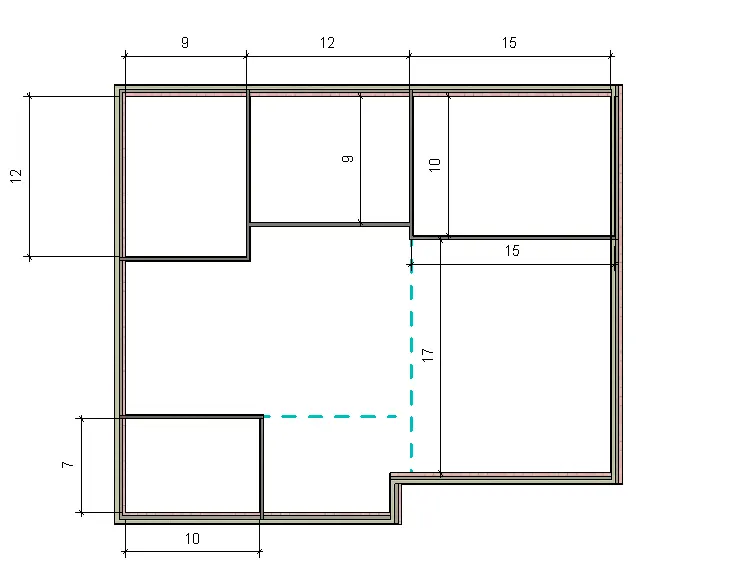
Now to give room name and area to them click on the architecture tab on the top right we can see the room icon click on that to selct room.
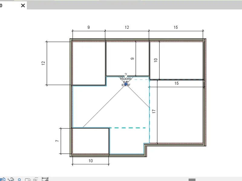
As we know we can use same process to give all the room tag.
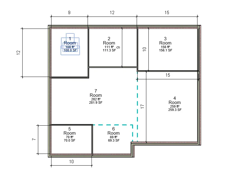
Now to change the name of it click in the room the we can chage the name.
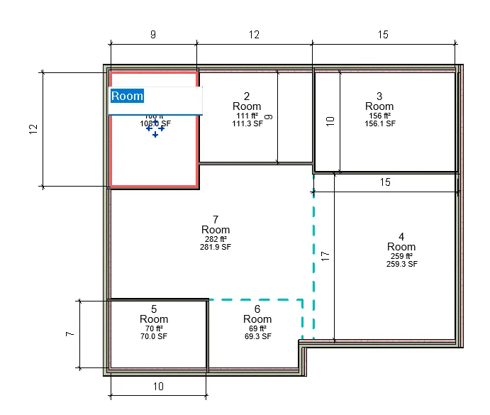
We can now give name to them.
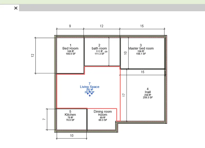
Result:-
As a result we now created room and gave the measurements and the ags to them to identify which they are with an proper spaces.
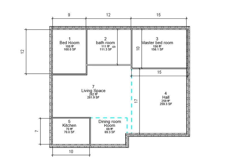
5) Based on week 2 assignment, the components to be included in a residential unit were inserted to the Revit file. Place these components in appropriate locations to add details to your residential model
a. Place Doors and windows in the wall at appropriate locations
b. The Living Room must include furniture set, couch table and TV desk and shelf cabinets
c. The Dining Room must include a table and chairs serving the purpose of eating
d. Bed Room must include a bed set, shelf, lighting and individual study desk and chair
e. Rest room should include bath tub and plumbing fixtures discussed in class
f. Kitchen should include countertops, gas stove cabinet and shelves to store food items
g. The wash/storage room can include washing machines and shelves to store clothes
All the components are available in Revit Library. Use them to place at appropriate locations to add details to your model. Use 3D navigation to check the model and its authenticity on a real time basis to verify the model
Aim:-
WE need to assaign a components in the week two project in the approprait location.
Intoduction:-
In this we need to add the components to the project in approprait location as per the residential model look. we need to be locate them and add them to the project.
Procedure:-
First we need to open week two project.
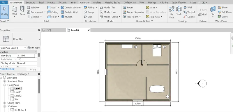
as we already have some doors and the window some components in the project they are not in approprait location we can now change them as per the requirements.
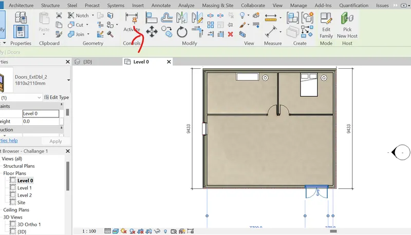
to change the location of the door click on the door oce it is selected drag and move it to appropriate location.
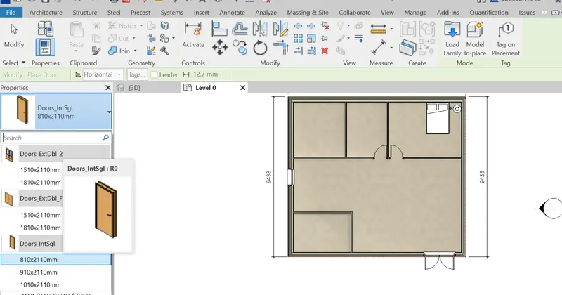
now to add doors click on the door add choose single door to the interior.
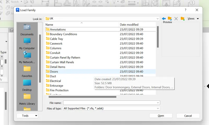
To choose more items choose door in architecture tab. Then click on the load family. then select the uk.
Now select doors.
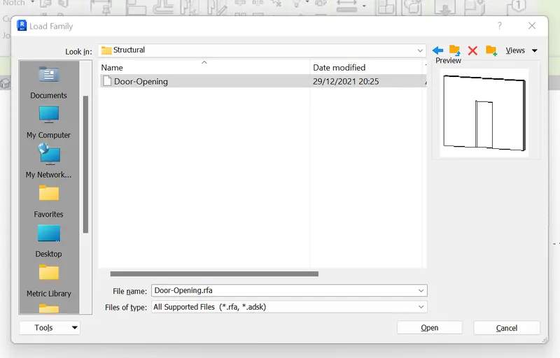
NOw click on the structural category. then click on the opening to add it to the kitch space.
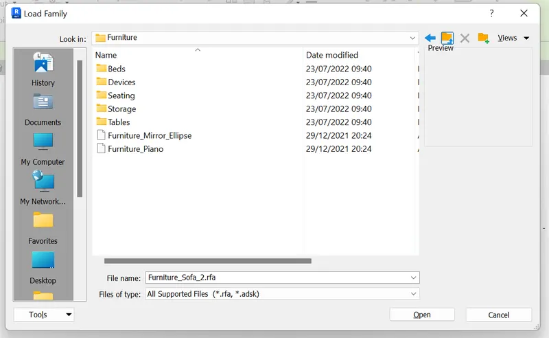
Now choose components in the family the choose the furinture. in the uk.
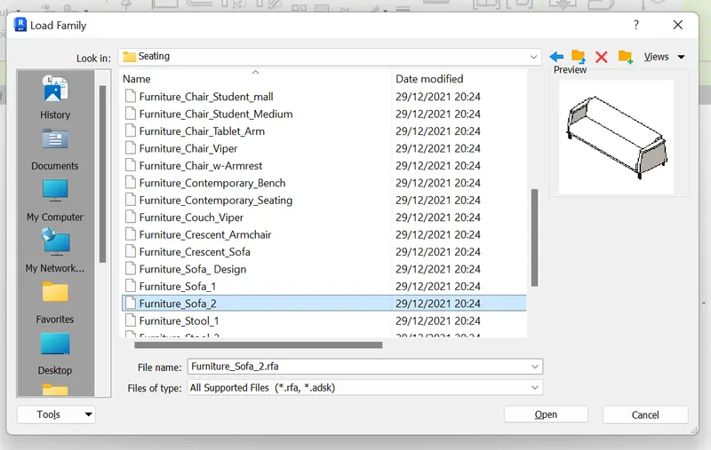
Now click on the table and slelct instance of sofa to add them in the living room.
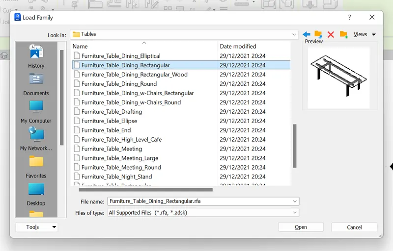
After that we can add the table in front of the sofa for the better look.
we need to got to componentas agains the select uk. Then select furniture and tables.
TO add windows to all the rooms we need to click on the architecture tab click on the windows.
then go to the load family. now select window categorie. then chiise the elements.
aftert that we can choose the size on the properties browser.
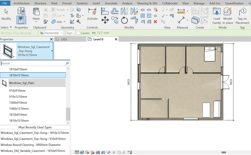
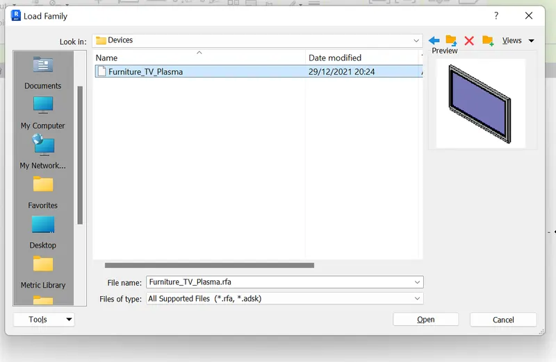
Now we will place the tv in the hall for that we need to go to load family again and then select the. furniture . then select the devices then on the tv.
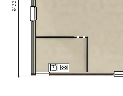
To add the kitchen elements. we need to go to the special equipment then select Domestic. Then we can see the kitchn items and domestic items so click on the items and add them.
TO add the bathroom item we need to go to components then click on the uk. Then click on the plumbing. architecture then click on the fixtures then click on bathroom.
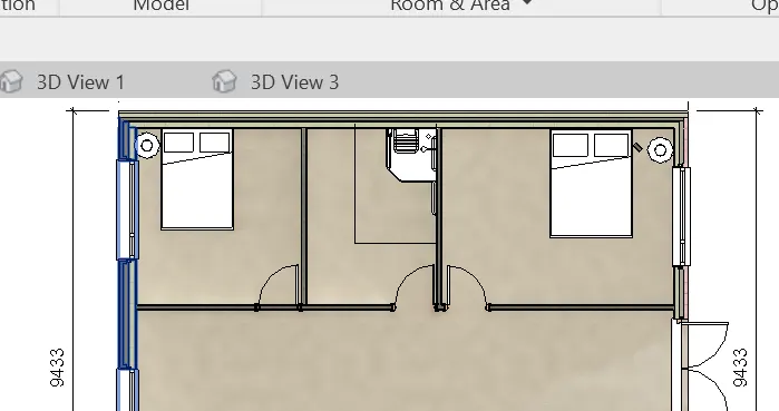
Now to fit lights we need to go to componends and then select the lighting family.
Result:-
As the result we can now see the details in the components as per the position in the project.