Creating Architectural and Structural model with 3D rendering using REVIT
Aim:To create the model of a structure architecturally and structurally and to develop the floor plans, sections, elevations, rendering views, sheets of the project using the rivet.
- In general the model of the structure is created architecturally and structurally.The model is developed architecturally to include the requirements of the structure according to the National building code and later the model is developed structurally to get to know the whether the artifial model is sturally safe or not.
- The model which is created architecturally should include the requirements and to cover the maximum area of the plot and the model should not be clumsy.The structural model should be developed in such a way that the model should be safe and it should not under go any deflections under the action of load and it should ensure the required life period. The model which is developed by both architecturally and structurally should also ensure the cost of the project The structural model should be over lapped with the architectural model or there will be the disturbance in the model during the execution and structural units like beams, columns,Doors may create the obstructions in the room space.
- The architectural model contains the details and sizes of the rooms,Furniture,electrical,plumbing where as the structural model contains the details and sizes of the structural units like beams,columns,slabs and foundation.
- In this challenge a multi unit residential apartment of G+2 is developed for both architecturally and structurally with all the basic requirements by following the guide lines of the national building code.
- The requirements of the structure may change according to the purpose of the model and the model is also developed to according to the geographic directions and the climatic conditins and the model developed should also regulate the heat and ventilation.
Procedure:
- The model that we need to create in this challenge is multi residential apartment.The residential apartment is generally developed for the small individual families.The residential apartment is generally comprises of the living room, bed room with attached toilets,kitchen with the dining facilities,Pooja room,study room or guest room and common toilet,gym or any other additional room are provided based on the requirements and the plinth area size.
To develop the model of the building we need to follow certain requirements according to the site and weather conditions.For this we need to follow the guidelines according to the standard code i.e national building code.So we need to create the model according to the guidelines.
- NBC follows certain guidelines for each and every building. The model created should follow these guidelines with out any undulations.
- The model created by the following the guide lines of NBS will satisfy all the basic requirements required for the inmates.
a.Height limitations:The height of the building should not exceed 15m as per the NBC cl 2.5 guidelines and if the building is more than 15 m then it needs to provide a lift for the building.
b.Area limitations: As per NBC cl 2.3The area of the building should not exceed 75% area of the plot.The area of building should not less than 40sqm in small and medium town and it should not less than 30sqm in metropolitan cities. The area of the building is permitted to less than 30sqm and should not be less than 15sqm in cluster planning.
In this challenge the area of the building is (13x12=156 sqm which is greater than 40sqm hence it is ok and it should not require any changes in the model.
c.Room sizing:In a building there will be multipurpose rooms and also individual rooms,As per the cl 3.3 of NBC the area of muitipurpose rooms should not be less than 12.5sqmm the area of individual rooms should not be less than 9.5sqm.In this model the rooms are multi purpose rooms (4x4=16 sqm) greater than 12.5 sqm and it will be ok.
d.Wall height: The height of the wall is the distance between the plinth beam and the roof. According to the NBC code the wall height is different for different rooms. For habitual rooms the height is 2.75m,Kitchen 2.6m,Bath room 2.2m.These are the minimum height of the walls over the plinth beam.
In this model the height of the wall over the plinth beam and the height of the walls in the first and second floor is 11' 5"(3.05m). The wall is created according to the NBC code.
e.Thickness of the wall based on the fire safety:The walls of the building should be designed to resist the fire to some extent and this should not be kept neglected as it is hazardous issue in the building construction. In NBC code table 1 gives the thickness of the building wall based on the material used for the construction of the wall.In the table the maximum wall thickness for the bricks and bricks with gypsum plaster is 190mm. In this model the thickness of wall is 12"(300mm).So The building is safe towards the fire safety positions.
f.Passage requirements: The paasage way is the space through which the entry or exit of thebuilding takes place in general for the huge and multipurpose buildings the entry or exit space should be more when compared to the size of the doors of the buildings.Buildings like educational institutions,Hospitals,Shopping complex etc, the entry or exit space should be more.For the individual residentialbuildings the passage way is nothing but the sapce infront of the door it should be equal to the width of the door. In individual residential buildings the space in front of the doors should be from cluster.
In this challenge the model is an indiviual residential apartment so the passage way will be the width of the main door i.e 5'(1500mm).Hence the building is safe under the passage way.
Procedure for creating a structural model:
- The model we need to create is the the multi residential apartment, so first we can create the structural model and later we can link the structural model to the architectural model.
- Click on the new option and select the required template structural and click on OK then the file with the required template is formed.
- To develop the model it is better to develop the levels which will give information at the various stages of the building.
- The level can be plotted only in the elevation view and it couldnot be plotted in the other plans it shows the level difference in the plan or top view of the building unit.
- The grid can be plotted in any of the model and it can be used in the plotting the plan of the building.
- To create the level click on the elevation in the project browser in the right of the window and it displays east,west,north and the south side view of the building model and select the desired elevation view of the building model which may be east,west,north,south.
- Click on the architecture option in the ribbon and it shows the level and grid option in the left of the ribbon and select level option.The level option is displayed only it is in the elevation view where as the grid option is displayed in all kinds of the views.
- Click on the level and select the pick line option and enter the level height as 10',15',20' etc and click on the window then the level line is plotted by displaying with the height of the lvel line.
- The height can be edited in the window itself by selecting the level line and the required height of the level line is entered and press enter.
- Here various levels like plinth level,first floor level,second floor level,foundationalevel,ground level are created with the distance of 11'5" between the floor levels and the height between the ground and foundation level is 8'.
- The grid can be plotted in any of the plan and elevation views of the building unit the grid can be plotted by selecting the architectural option in the ribbon.
- Click on the architectural option and we can able to see the grid option then click on the grid option and selcet the pick line option and edit the grid distance and the grid line is plotted.
- Generally the grid lines are plotted in the longitudinal and in transverse direction.The grid lines are named with A,B,C,D,E etc in one direction and 1,2,3,4 etc with the other directions.
- The columns are selected in the structural icon in the ribbon bar and the colum size is editted to the 300x450mm and the columns areplaced in the position of the grids where we need in the model and the columns are created from the ground level to the roof level with the height of 37'8"(11.5m) .
- Now click on the foundation icon in the ribbon bar and select the isolated footing and select the size of the footing as (1800mmx1800mm) and place isolated footing in all the columns at the foundation level.
- Now the column base offset is changed from the ground level to the foundation level.
- Click on the beam option and select the beam which we need to create in the model and select the beam and plot the beams in between the columns at the floor level of the building.
- The beam is cretaed in the floor levels and later its base offset is change to avoid the overlap with the slab of the building.
- After the creation of the beams click on the floor icon in the ribbon and select the floor and edit the thickness to the 150mm and create the slab in the floor levels of the building.
- The structural elements can be copied from one floor to the other level when they are of same size, shape and also follow the same material properties.
- Opening for the stairs and the elevators are created by using the shaft option.Click on the shaft option and select the levels in the model and edit the level height and create the opening to of required size.
- The created structural model with the floor level and the 3D view of the model is shown below.
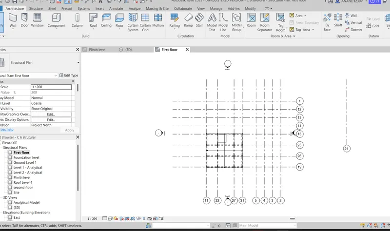
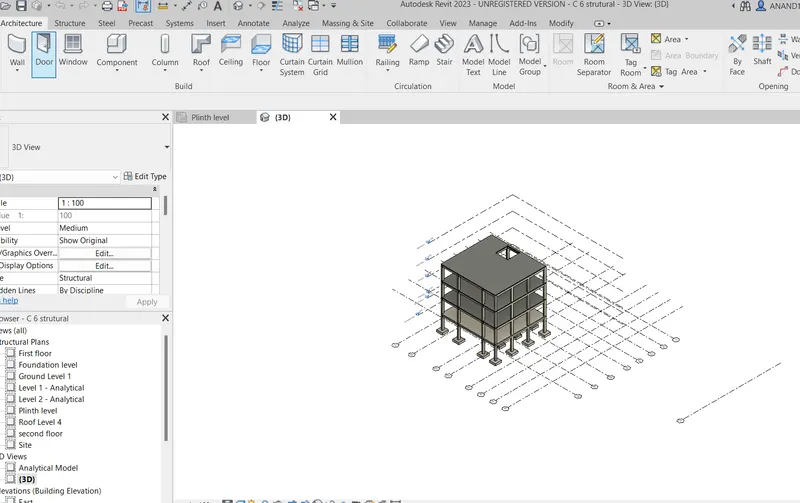
Procedure for creating a architectural model:
- After the creation of the structural model the building model is linked to the architectural model and the walls,furniture, plumbing and lighting fixtures are developed to full fill the requirements of the model and the architectural model is created.
- Now open the new rivet file with the architectural template and select the manage option in the ribbon and select the rivet link and insert the structural file to the architectural file. For this file all the architectural elements are inserted.
- Click on the wall option and select the wall and change the material properties of the wall i.e masonry with the brick and add the plaster on both the interior and exterior faces of the wall and the thickness of the wall after the plaster surface should be 300mm and plot the walls in the outer side of the building.
- Now again select the wall and create the duplicate of the wall and edit the masonry thickness of the wall 100mm and create the partition walls of the building in the inside of the building.
- The partition walls are created to separate the attached toilets for the bed rooms and to separate the pooja room and the gym in the building.
- For the ground floor verandah is created where the walls are eliminated and in the first floor and the second floor glass panels are provided for the balcony of the building.
- For the first floor and the second floor create the walls whether the load bearing or the partition walls.
- After the separation of the rooms with the walls, Now the rooms are provided with the doors and windows for the access into the building.
- Click on the door icon on the ribbon and select the doors option and edit the door to the size of 1000x2100mm and insert the doors for bed rooms and the kitchen.
- Click on the doors again and duplicate thedoor and edit thedoor and change the door to the size of 800x2100mm and insert the doors for all the toilets and also again edit the door to a size of 1500x2100mm and insert this door as the main door of the building.
- Now click onthe window option and selcet the window of the building and edit the size of the builiding to 1200x1200mm and insert the windows for the bed rooms,pooja and the kitchen.
- More over after the insertion of the doors and windows now the model is inserted with furniture,electrical,plumbing elements from their respective families options.
- Click on the component icon in the ribbon and insert the furniture elements like bed,hair dresser,sofa,dining table etc an plumbing elemnets like watercloset,shower etc and electrical elements like interior lights are inserted for the model. Now the same elements are aligned to the first floor and the second floor of the building.
- The stairs are inserted in the shaft created in the structural model,click on the stair option and select the stair model and edit the flight height ,step width,height of the riser and the levels in which the stair case is to be placed and place the stair case in the levels.
- The stair case is also aligned to the first and second floors using the copy monitor option if the model of the staircase is same.
- After the insertion of the interior elements now the exterior elements like lighting,parking and trees for the architectural and eco friendly nature trees are inserted in the architectural model.
- Click on the component option and click on the load family option and the external lighting nadd trees are placed by loading them from their respective families.
- The architectural model after insertion of all the elements from their respective families is shown below.
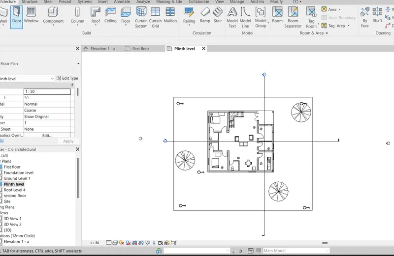
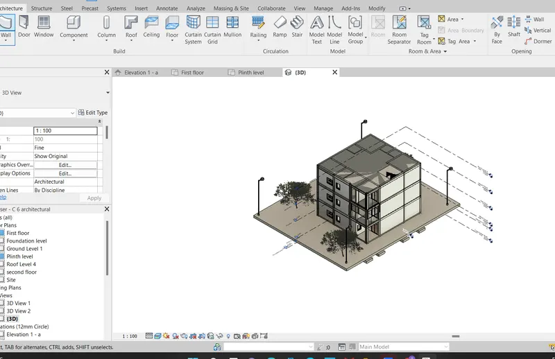
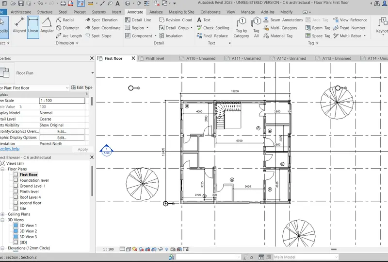
Floor plan with the annotations.
- The model can be converted to various views which may be architectural or structural view. But the dimension of the views may not be similar all the time so we need to create the dimension for the which are different to each other.
- After creating the dimension for the views the rooms sizes can be get know very easily with out any disturbance. The room sizes may vary from one level to other.
- The dimensions help to get to know the sizes of the room and it plays key role if there required any changes in the size of the room before the approval of the drawing.
- The dimensions of the architectural plan is distance between the walls where as the dimensions in the structural plan is the distance between the beams or the structural members in the plan.
Procedure:
- After creating the model of the building unit ,To develop the dimension of a particular view of the model click on the views icon on the ribbon and select the plan view of the building and it shows the various options like floor plan,structural plan,ceiling plan,plan region etc for the model and select the required model option and click on the ok and the required model get displayed on the window.
- Now enter VG command and some of the units in the model like Doors,Furniture may be hidden to avoid the overlap between the Dimension and the elements in the model.
- Now click on the Annotate bar and select the linear command in the ribbon and the dimensions is measured for the architectural or structural paln view of the building.
- Care should be taken to visible the dimensioning formed in the plan view of the building with out any overalp.
- Now the dimensions for the architectural and structural view of the building are formed as are shown below.
Elevation of the building
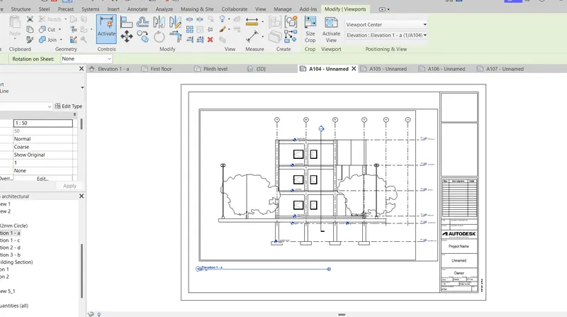
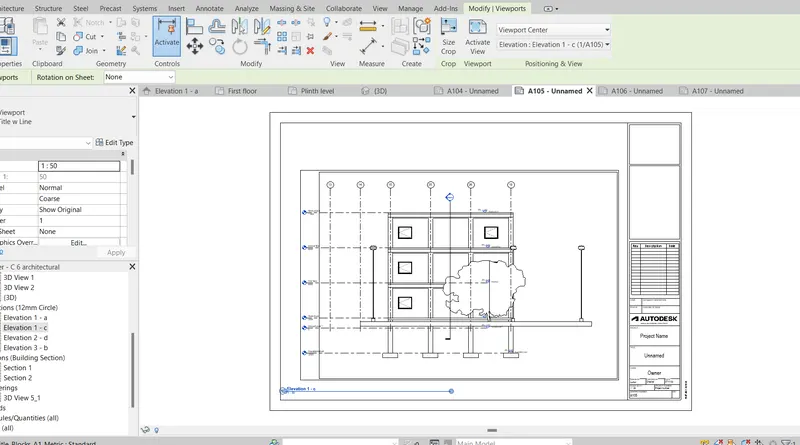
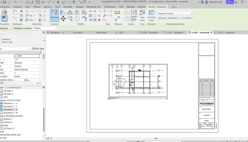
- Elevation is the outlook view of the building from the front or back or from the sides of the building.Elevation gives the information about the building length,width,height and also gives the details of the architectural appearence of the building.
- The Elevation gives the details of the various levels of the building i.e plinth level,floor finish level,lintel level,roof level etc and the level of the building are created or inserted only in the elevation view of the building.
Procedure:
- The elevation view of the residential view of the building can be formed by clicking on the view tab in the ribbon bar.Select the floor level in the model and now select the elevation tab in the ribbon bar and now the ribbon bar is consisted with elevation option and select the elevation option.Click on the elevation option and an arrow mark is obatained at your cursor and place the arrow mark on the respective side i.e on the side or in the front or in the back side of the model.
- The arrow mark states the elevation view of the model,Now click on the elevation view in the project browserin the left of the window and there we can see the elevation views with the specified names i.e elavation A,Elevation B, ElevationC and ElvationD .
- The name of the elavation can also cahnged like front elevation,back elevation or side elevation of the building.
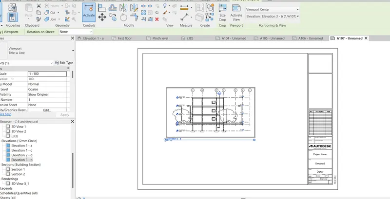
- The below model shows the elevation views of the building in all the four sides, The elvation shows the levels of the building i.e the floor level 0'0" and the slab level 37'8"'.
- The elevation views formed for the residential building is shown below.
Section of the building:
- Section is the view of the building fromed by cutting the building in a direction either transverse or longitudinally.It gives the inter details of the building when a cuting is paseed through it .
- The section is imporatnt to know about the internal profile of the beam, column,footing,door,window and any other unit in thebuilding model.
- The section gives the internal material profile of a building unit when a section line is paseed through the particular building unit.
Procedure:
- The sectional view of the residential view of the building can be formed by clicking on the view tab tab in the ribbon bar.The section can be created in the floor level view of the model and the sectional view can be obtained in the project browser in the window.
- Select the floor level in the model and now select the view tab in the ribbon bar and now the ribbon bar is consisted with section option and select the section option.Click on the section option and draw a line on the floor plan in which the section is to becreated.After the plotting of the line the sectional view can be formed in the project browser.
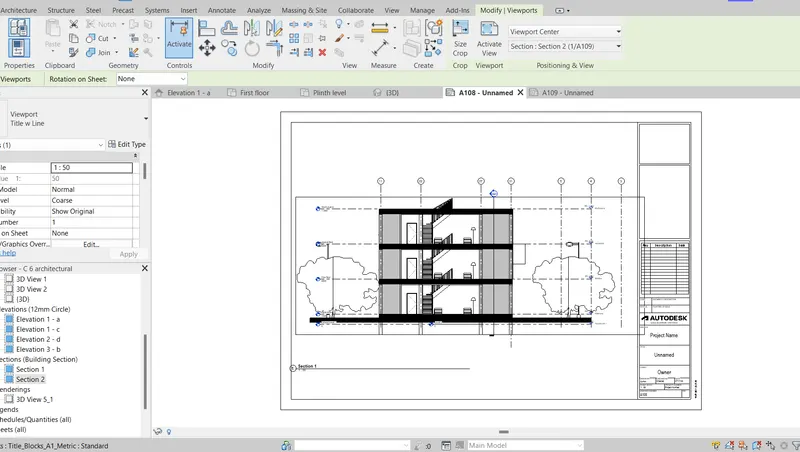
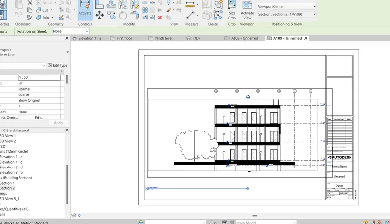
- Now click on the section view in the project browser and the section view is obtained with all the internal details of the building along the section lineplotted and it also gives the internal material properties of the building in which section line pased through nad we can also create number of section views according to the building design and building modelling.
- Section view also exhibits the details of the level of the building.
- The section view formed for the residential building is shown below.
Rendering view of the buildings:
- The sheets are created to insert the particular view of the drawing to a required scale. A drawing is to be submitted after creating the sheet and inserting the required view in the sheet .
- After creating the sheet the drawing is to be insertedd and the details or schedules of the units in the building are also can be inserted in to the sheet.
- The camera view is the internal view of the building unit which forms the rendering view of the model.
- The rendering view is the image of the building formed by the camera view of the building.
Procedure:
- The camera view can be created by the view tab in the ribbon in the window, select the ribbon and click on the 3d view and select the camera view and place the camera in the respective position at the rooms and the camera view is created in the project browser and the position of the camera is adjusted and the elevation of the camera can be editted in the properties browser.
- The camera view is rendered by clicking the render icon in the ribbon and the resolution of the camera view are ediited and rendered to create the image.
- Now the camera view is created and inserted in the sheet for the submission to client.Click on the sheet option in the project browser and drag the particular view in to the sheet.
- The sheet of the view is formed with a particular scale, for the better view we can change the scale of the drawing in the sheet.select the drawing in the sheet and change the properties of the drawing from the properties browser.
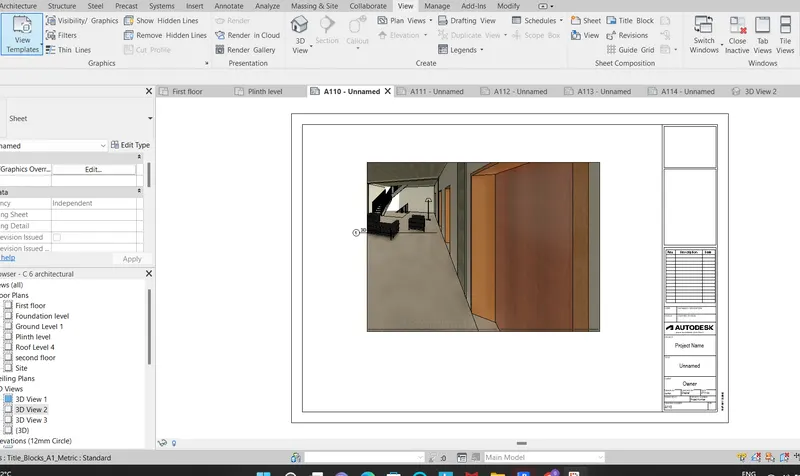
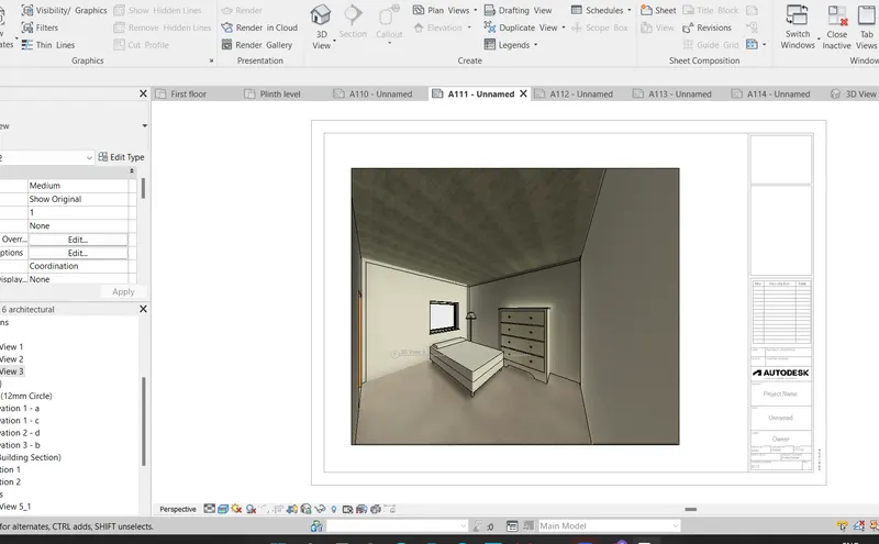
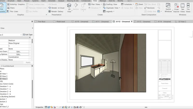
- For the model created in the challenge we can create the sheet for the camera view of the living room, dining room and bed room etc
- Click on the sheet inthe ribbon bar and then select the size of the sheet and click ok,now drag the camera view of the dining room and again create another sheet and insert the camera view of the bed roomto the sheet.In the same way we can create the sheets for the camera view of the living room created for the residential building
- The details of the project, client are entered for each and every sheet which gives the details of the drawing,these details can be entered either in the sheet itself or otherwise the details are entered in the project information option.
- The scale of the drawing in the sheet can be adjusted from the properties bar.
- The sheets created with the various camera views and rendered view of the residential building created in this challenge are shown below.

Printing the sheets of the drawing:
- After the completion of the creation of the sheets the drawings are to be printed for the submission to get the approval from the client.
- The drawings are printed by applying the command ctrl+p and the preview of the sheet is visibled and the corrections to the scale is applied if needed and the sheets are printed in require number of quantity.
- All the sheets in the architectural and as well as structural drawings are printted and submitted to get the approval.
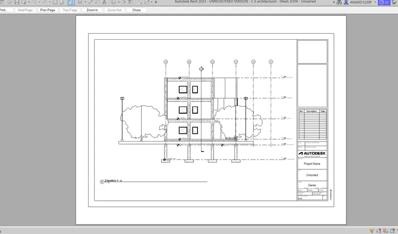
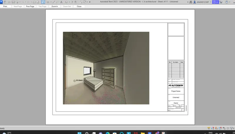
In this way all the drawings are printed in the required number of quantity and submitted to get approval or used for the execution.