Creating Architectural and Structural model with 3D rendering using REVIT
Ans 1)
Aim : Selecting the type of structure you want to build.
So, here I want to build a office building.
Ans 2)
Aim : Assuming the reasonable assumptions for geographic and location details for the project modeling. Based on assumptions and type of structure selected identify the modeling requirements from NBC
Lets assume the building is located in Chennai. So the modelling requirement for the Chennnai location as per NBC are mentioned below:
- The open space around the building shall not be less than 4.5m.
- The type of construction as type 2 construction, the FAR value for the business building shall be taken as 2.9.
- The plot size is taken as 40mx70m i.e, 2800m^2 and the individual floor area is 2000m^2. Hence FAR value obtained is 2.14 which is within the prescribed limits as per NBC.
- The width of the road abutting the building is taken as 9m(30').
Ans 3)
Aim : Using the structural model, include the following components based on the type of structure selected.
Procedure:
- Open the REVIT software by double clicking on it.
- On the left side, in the models section NEW option is available click on it.
- Similiarly at the top left corner there is File menu click on it and select the new file.
- Select structural template press ok.
- Again go to the file menu and select the Save option.
- Give the name to the project as "Challenge 7" and click on the save option.
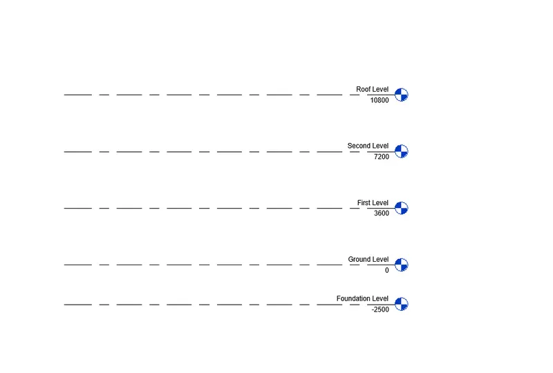
- Go to the elevation view and add levels either from structure tab or from architecture tab.
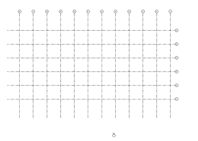
- Now go to the foundation level and add the grids to the model from structural tab.
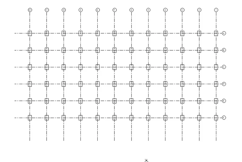
- To add foundation go to the structure tab, there is foundation tab in it, select the isolated.
- Now select the at grid option and select all the grids.
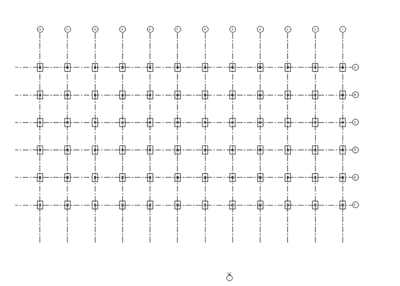
- To add columns, again in structure tab there is option for column.
- Select the column option and click on at grid option and select the grids.
- Select all the columns and give the top level as second level.
- Now Select the ground level.
- And again in structure column there is option for the beam,click on it .
- select the at grid option and select all the grids.
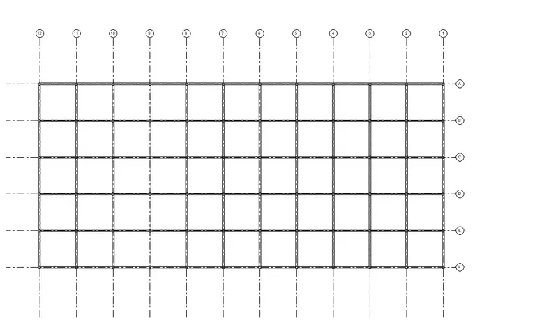
- Similiarly draw the beam at each level.
- Now to draw the floor, select the floor option either from architectural tab or from structural tab.
- Select the rectamgle option and draw the floor.
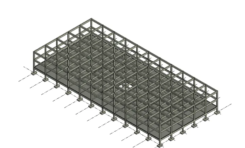
- Similiarly draw the floors at each level.
- For the floor opening for elevator and stairs, there is dedicated shaft option in both the structural and architectural tab.
- Now select the rectsngle option and give the area for the shaft and press enter.
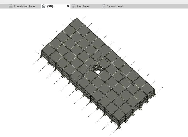
Ans 4)
Aim : Using the architectural model, include the following components based on the type of structure selected.
Procedure:
- Select the wall option from architectural tab and draw the walls as per the requirements of the project.
- From the properties panel > go to edit type and give the material to the wall and click ok.
- For the interior partition wall, again select the wall option from the architecture tab, and select the wall type as interior wall.
- Now in the project browser, from the families add the components to detail the room .
- From the architecture tab, add the doors and windows to the model.
- Again add the stairs from the architect tab and press enter.
- Select the side walls and from the properties, select the wall type as stonefront.
- Again from the project browser> go to families > add the exterior and interior lightening fixtures.
- In the massing and site tab there are option for the topography and other site components add them from there as shown below.
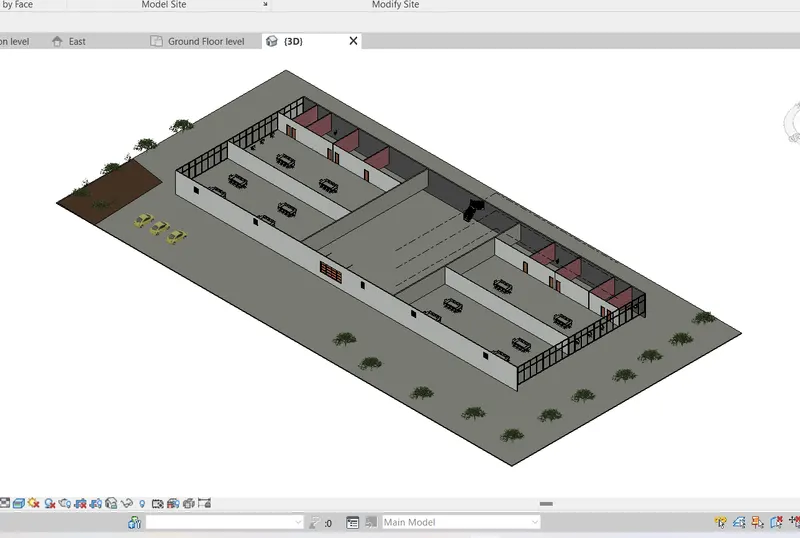
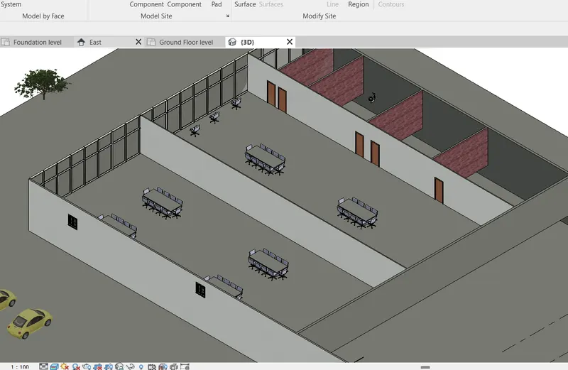
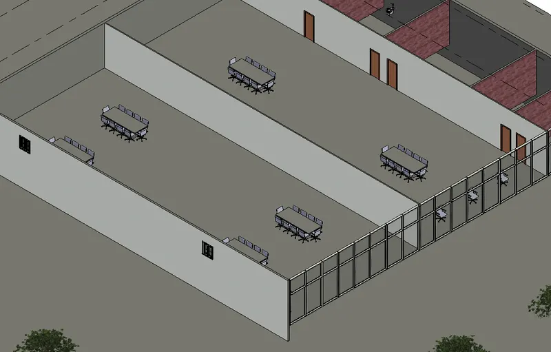
Ans 5)
Aim : Providing the set of templates for the architecture and structure model.
Procedure:
- In the view tab there is a option called sheets.
- Select the sheet option, and select the titleblock and press ok.
- Now drag the floor plan to the sheet and rename the sheet as Floor plan and press enter.
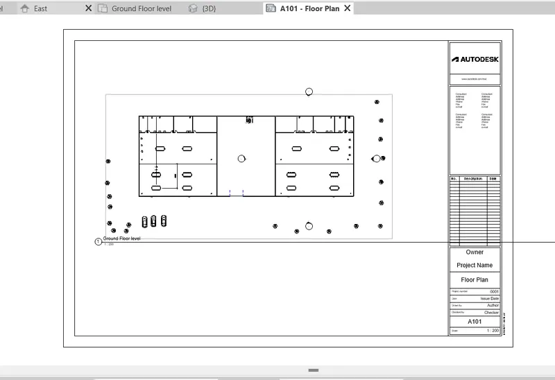
Again for the Elevation sheets do the above process.
- Similiarly, go to view tab> select the Sheet option>select the title block>press ok.
- NOw drag the elevation to the sheet and resize it accordingly.
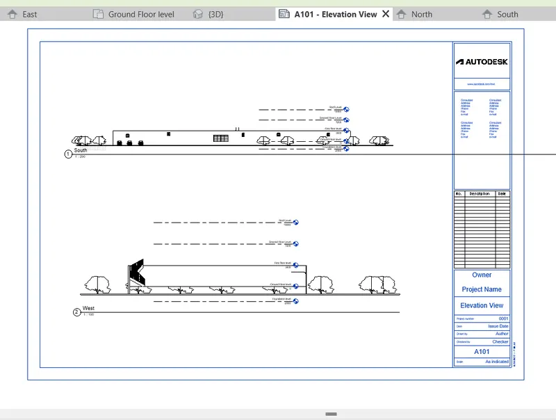
Similiarly drag the section view to the sheet and fit it accordingly.
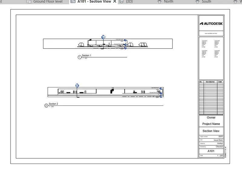
Ans 6)
Aim : Renderring the images by using renderring setting and include the renderred images into the drawing sheets.
Procedure:
- Go to the view tab and there is a option called render to renderring the images.
- Or you can type RR which is the shortcut key for renderring.
- By clicking the render option a dialog box is open as shown below.
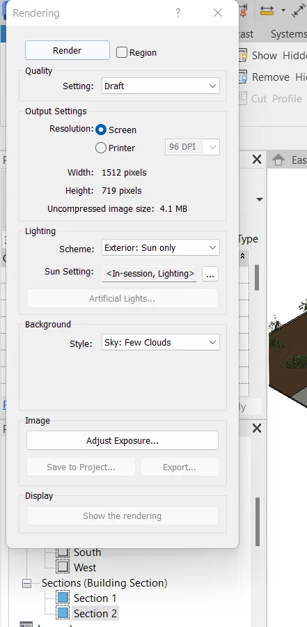
- Adjust all the requirement Like quality, lightening fixture, output setting and background.
- After that click on the render button.
- As a whole model it will take to much time, so we can put camera in the rooms and capture the 3d views and render them.
- Now to draw the sheets, Goto view tab > Goto sheets option > select the titleblock > press ok.
- Drag the render view to the sheets and name the sheet as rendered view.
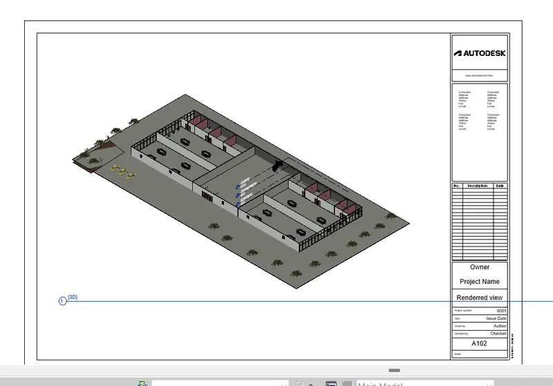
Ans 7)
Aim : Printing the set of drawing sheets.
Procedure:
- To print the sheets Press Ctrl+P , a display appears on the screen as shown below.
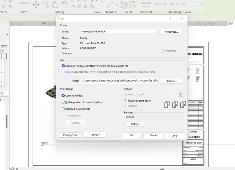
From here we can save the file in pdf format or we can print from here.