Creating a Floor plan, Footing detail and Isometric view using AutoCad
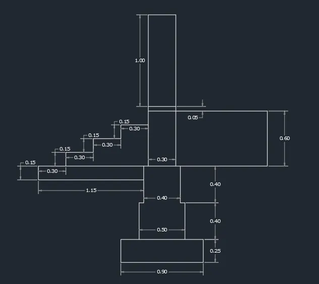
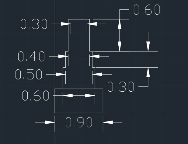
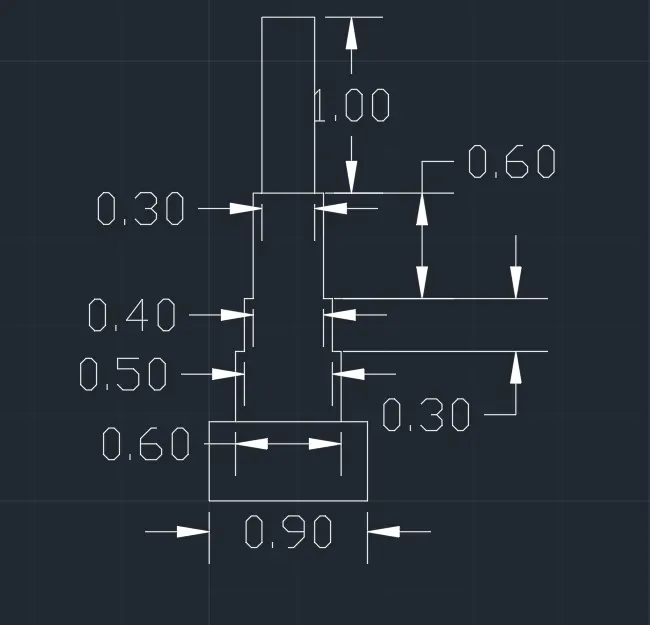
1) Aim: To create cross section of footing by using Autocad
Procedure
Step 1:
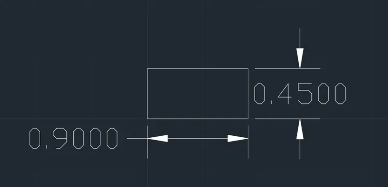
Select rectangle tool from the draw panel or by using rectangle command.
Specify the first point (5,5) in the command prompt and press enter.
Select "dimensions" from the command prompt.
Enter the length as 0.9 and press enter.
Enter the height as 0.45 and press enter.
Press "esc" to finish.
Step 2:
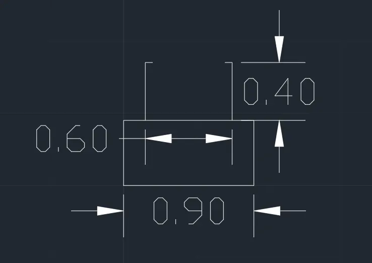
Use line command and draw a line of length 0.4 from left corner.
Type "offset" in the command prompt and select erase.
Select "yes" to erase the source object after offset.
Enter the offset distance as 0.15.
Keep the pointer in the right side and click so that the line get offsetted.
Now keep the pointer at the end point and draw line for a distance of 0.05 to the right.
Again type "offset" in the command prompt and select erase.
Select "no" to erase the object after offset.
Enter the offset distance as 0.6
again keep the pointer on the endpoint and draw line using line command for a distance of 0.05.
press "esc" to finish.
Step 3:
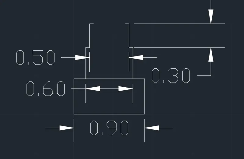
Use line command draw a line of length 0.3 in positive Y direction.
Using offset command offset the line to a distance of 0.5.
Now keep the pointer at the end point of both line and draw line for a distance of 0.05 Positive and negative X-direction.
Step 4:
Use line command draw a line of length 0.6 in positive Y direction.
Using offset command offset the line to a distance of 0.4.
Then drew the line of length of 0.4 in positive X direction.
Step 5:
Use line command and draw a line of length 1in positive Y direction.
Type "offset" in the command prompt and select erase.
Select "yes" to erase the source object after offset.
Enter the offset distance as 0.05.
Keep the pointer in the right side and click so that the line get offsetted.
Again type "offset" in the command prompt and select erase.
Select "no" to erase the object after offset.
Enter the offset distance as 0.3
again keep the pointer on the endpoint and draw line using line command for a distance of 0.3.
Press "esc" to finish.
2) Aim: To create cross section of Isolated footing by using Autocad
Procedure
Step 1:
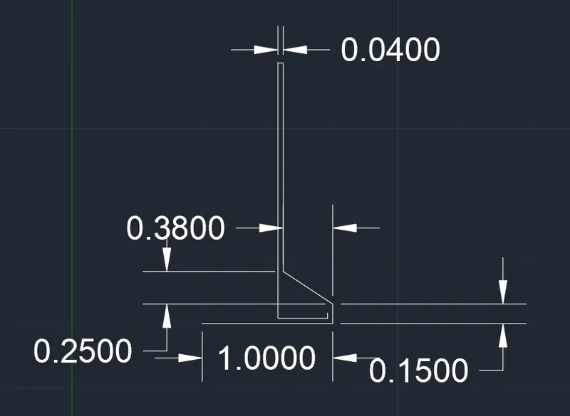
Select "Line" tool from the draw panel or type line in command prompt and press enter.
Specify the first point (1,1) in the command prompt and press enter.
Specify the next point 1 unit in positive X direction.
Specify the next point 0.15 unit in positive Y direction and press enter.
Specify the next point (@-0.38,0.25) and press enter.
Specify the next point 1.6 unit in positive Y direction and press enter.
Specify the next point 0.04 unit in negative X direction and press enter.
Specify the next point 1.96 unit in negative Y direction and press enter.
Specify the next point 0.38 unit in positive X direction and press enter.
Specify the next point 0.04 unit in positive Y direction and press enter.
Press "esc" to finish.
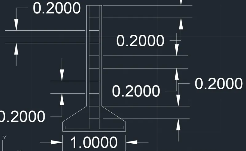
Step 2:
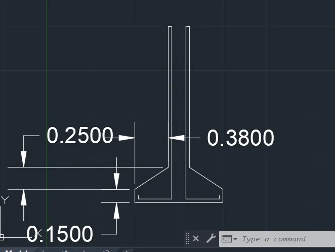
Select "Line" tool from the draw panel or type line in command prompt and press enter.
Specify the first point (1,1) in the command prompt and press enter..
Specify the next point 0.15 unit in positive Y direction and press enter.
Specify the next point (@0.38,0.25) and press enter.
Specify the next point 1.6 unit in positive Y direction and press enter.
Specify the next point 0.04 unit in positive X direction and press enter.
Specify the next point 1.96 unit in negative Y direction and press enter.
Specify the next point 0.38 unit in negative X direction and press enter.
Specify the next point 0.04 unit in positive Y direction and press enter.
Press "esc" to finish.
Step 3:
Select "Line" tool from the draw panel or type line in command prompt and press enter.
Specify the first and second point at the both ends and press enter.
After that, type "copy" in command prompt and select line and press enter.
Specify the base point and press enter.
Select the array from command prompt.
Enter number of items to array as 10 and press enter.
Now specify the distance as 0.2 betwwen the array lines and press enter>
Press "esc" to end.
3) Aim: To create a line diagram of two bedroom building using AutoCAD.
Procedure:
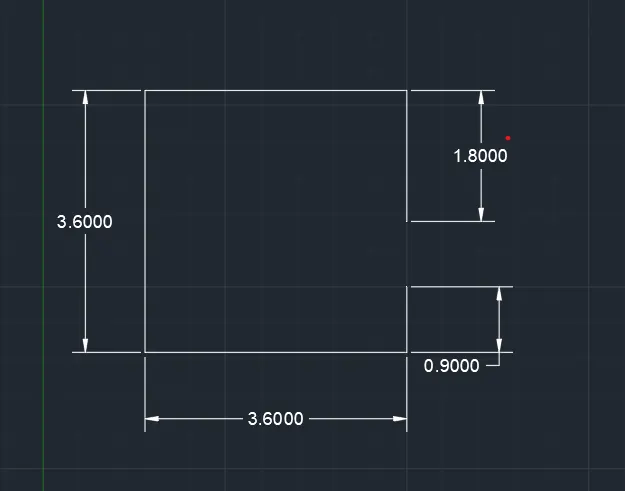
Step 1:
Select "Line" tool from the draw panel or type line in command prompt and press enter.
Specify the first point (5,5) in the command prompt and press enter..
Specify the next point 0.9 unit in negative Y direction and press enter.
Specify the next point 3.6 unit in negative X direction and press enter.
Specify the next point 3.6 unit in positive Y direction and press enter.
Specify the next point 3.6 unit in positive X direction and press enter.
Specify the next point 1.8 unit in Negative Y direction and press enter.
Step 2:
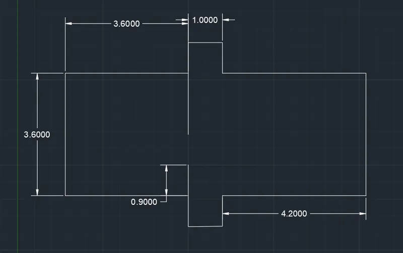
Select "Line" tool from the draw panel or type line in command prompt and press enter.
Specify the first point and press enter.
Specify the next point 1 unit in positive X direction and press enter.
Specify the next point 0.9 unit in negative Y direction and press enter.
Specify the next point 4.2 unit in positive X direction and press enter.
Specify the next point 3.6 unit in negative Y direction and press enter.
Specify the next point 4.2 unit in Negative X direction and press enter.
Specify the next point as 0.9 in negative Y direction and press enter.
Specify the next point as 1 unit in negative X directionand press enter.
Specify the next point as O.9 in positive Y directrion and press enter.
Step 3:
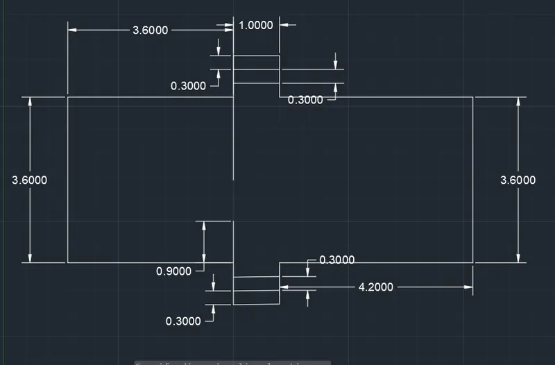
Type "Copy" in the prompt command and press enter.
Select the line and specify the base point and press enter.
Select the "Array" from the command porompt and press enter.
Enter number of item to array as 3.
Specify the second point as 0.3 and press enter.
Press "Esc" to finish.
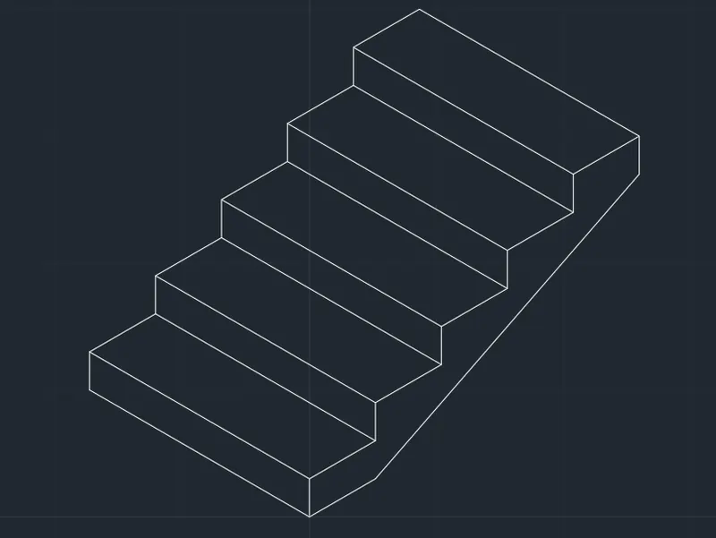
4) Aim: To create Isometric View of Steps using AutoCAD.
Procedure :
Select the isometric snap from drafting setting.
Select "Line" tool from the draw panel or type line in command prompt and press enter.
Specify the first point and press enter.
Select the isoplane left and specify the next point and press enter.
Change the isoplane to right and again specify the next point and so on.
Press "esc" to finish.
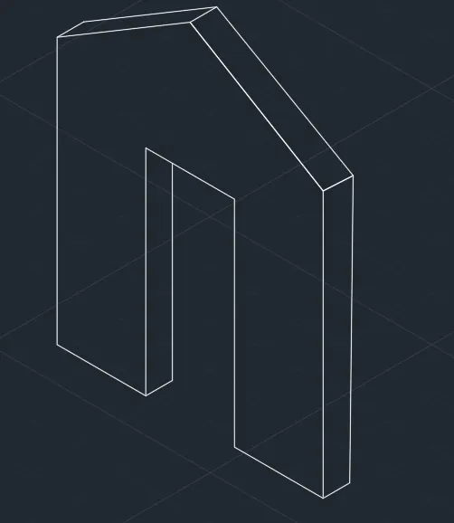
5) Aim: To create a isometric view of gable wall using AutoCAD.
Procedure:
Select the isometric snap from drafting setting.
Select "Line" tool from the draw panel or type line in command prompt and press enter.
Specify the first point and press enter.
6) Aim: To create a cross section of load bearing wall over spread footing using AutoCAD.
Procedure:
Select rectangle tool from the draw panel or by using rectangle command.
Specify the first point (5,5) in the command prompt and press enter.
Select "dimensions" from the command prompt.
Enter the length as 0.9 and press enter.
Enter the height as 0.25 and press enter.
Use line command and draw a line of length 0.4 from left corner.
Type "offset" in the command prompt and select erase.
Select "yes" to erase the source object after offset.
Enter the offset distance as 0.2.
Keep the pointer in the right side and click so that the line get offsetted.
Now keep the pointer at the end point and draw line for a distance of 0.05 to the right.
Again type "offset" in the command prompt and select erase.
Select "no" to erase the object after offset.
Enter the offset distance as 0.5
again keep the pointer on the endpoint and draw line using line command for a distance of 0.05.
press "esc" to finish and so on.