Creating Architectural and Structural model with 3D rendering using REVIT
AIM:- TO MODEL THE BUILDING WHICH DRAFTING, DESIGN, AND ENSURE THE SAFETY OF ALL THE COMPONENTS. MAKE SURE EVERY RESIDENTIAL UNIT IS FULLY FILLED BY THE MODEL OF THE PROJECT.
INTRODUCTION:- I select the multi-unit Residential Apartment.
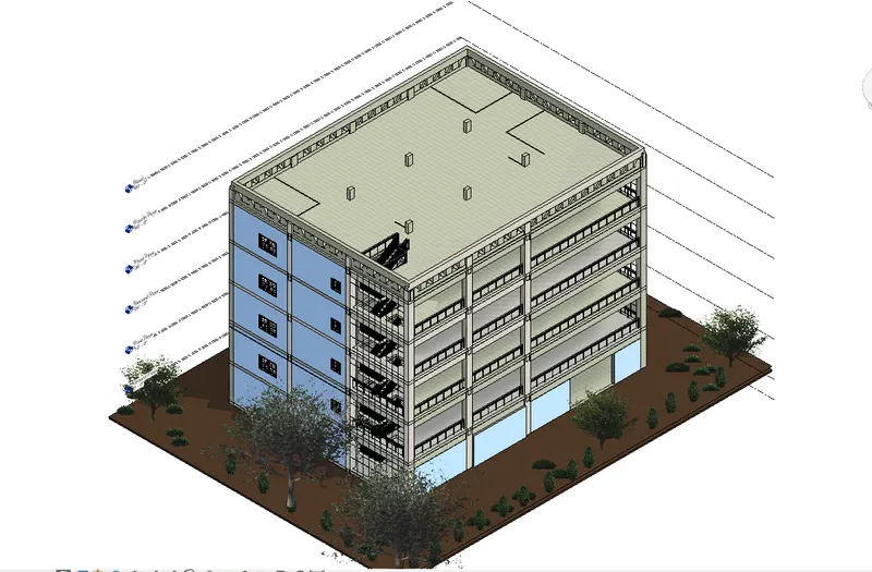
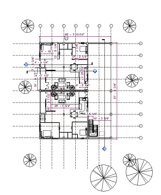
I model an 8 multi-unit Residential Apartment. Which carry G+4 floors and every floor carries 2 apartments.
The size of the building is 60' X 80'
The topography location is Prayagraj-> U.P-> India ( under guidelines of NBC)
In this project, we use structural and architectural components. In this project, we draft doors, walls, elevator, staircase, column,
beam, and other structural and architectural components.
PROCEDURE:-
Structural model, include the following components based on the type of structure selected
a. Foundation – Isolated / Wall/Matt Foundation
b. Columns
c. Beams Connected to Columns
d. Roof Framing/ Truss
e. Floor / Decks
f. Floor Openings for Elevators and Stairs
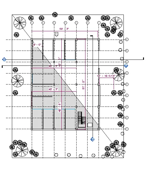
- FIRST WE SKETCH A STRUCTURAL MODEL
- SKETCH GRIDS AND LEVELS
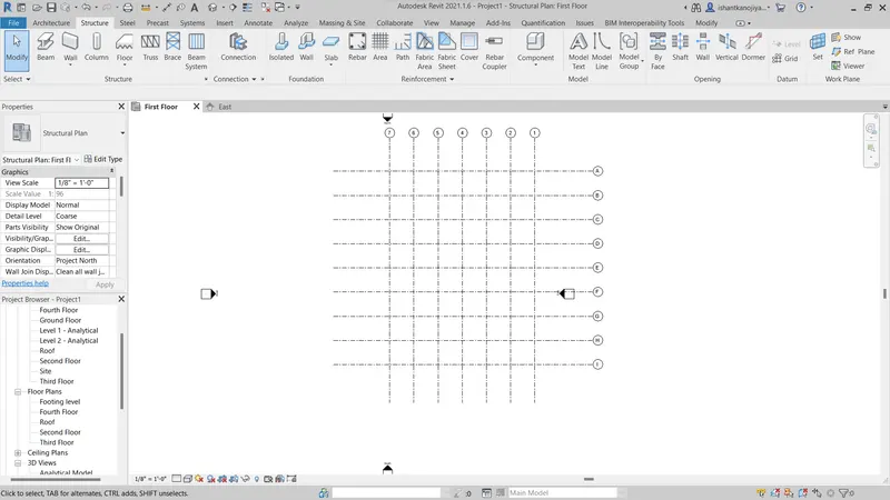
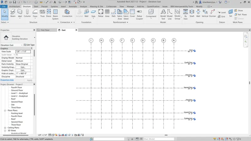
- PROVIDE FOOTING, COLUMN, BEAMS
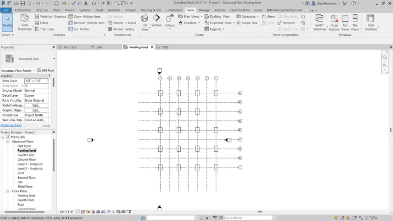
- GO TO FOOTING LEVEL> SELECT ISOLATE FOOTING > SELECT LOCATION WHERE YOU PLACED FOOTING> SELECT SIZE AS PER REQUIREMENT
- GO TO COLUMN> SELECT SIZE OF COLLUM (OUTER SIDE 18X24 OR INNER SIDE 12X18)> SELECT TOP-LEVEL AS ROOF LEVEL> SELECT BOTTOM LEVEL AS FOOTING LEVEL> SELECT LOCATION WHERE YOU PROVIDE AS PER REQUIREMENT.
- SELECT SLAB> SELECT STRUCTURAL SLAB> SELECT RECTANGLE > SELECT THICKNESS OF SLAB(FOOTING LEVEL 6" )> SELECT OUTER SIDE OF EDGE COLUMS> PRESS OK
- BEAM CONNECTED TO COLUMN
- GO TO BEAM > SELECT SIZE OF BEAM(OUTER SIDE 169X32 OR INNER SIDE 16X24)> SELECT COPY TO TO ALL BEAMS > GOTO ALIGNED TO SELECTED LEVEL > PRESS OK
- GOTO FLOOR> SELECT STRUCTURAL FLOOR> SELECT 6"GENERIC CONCRETE FLOOR> SELECT RECTANGLE > SELECT POINT MID AT ALL EDGE COLUMN> PRESS OK
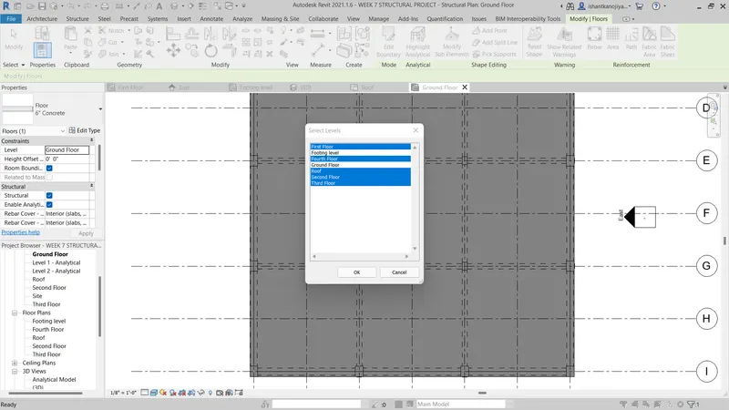
- SELECT FLOOR > PRESS COPY > PASTE ALIGNED TO LEVELS > SELECT FIRST, SECOND, THIRD, FORTH, ROOF> PRESS
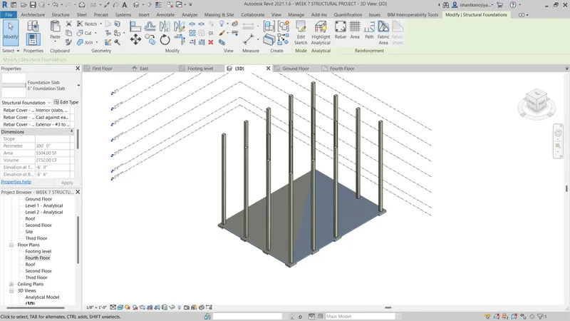
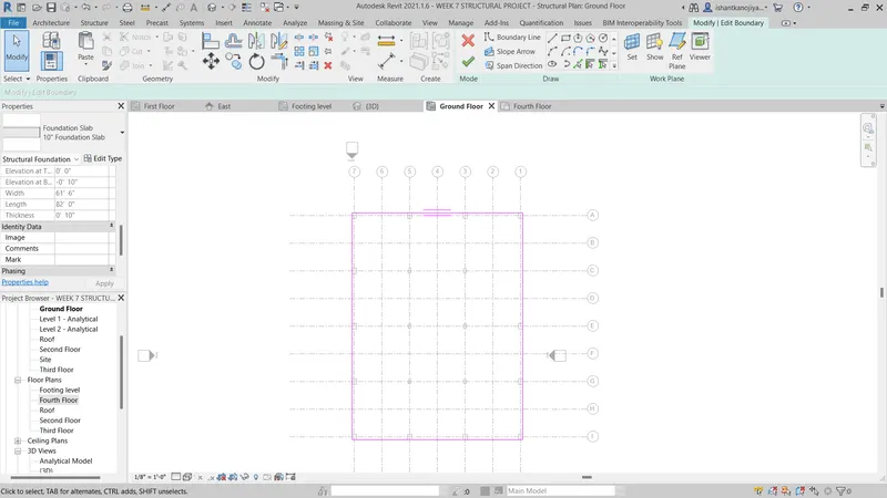
- EXTEND COLUMNS 3'
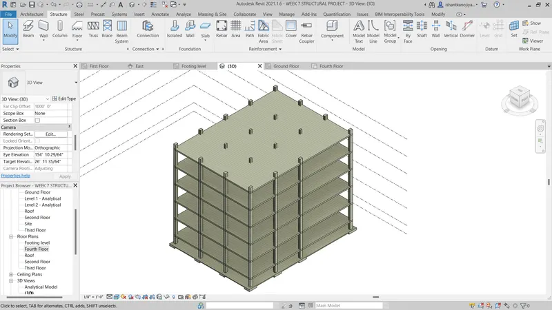
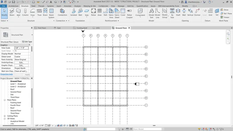
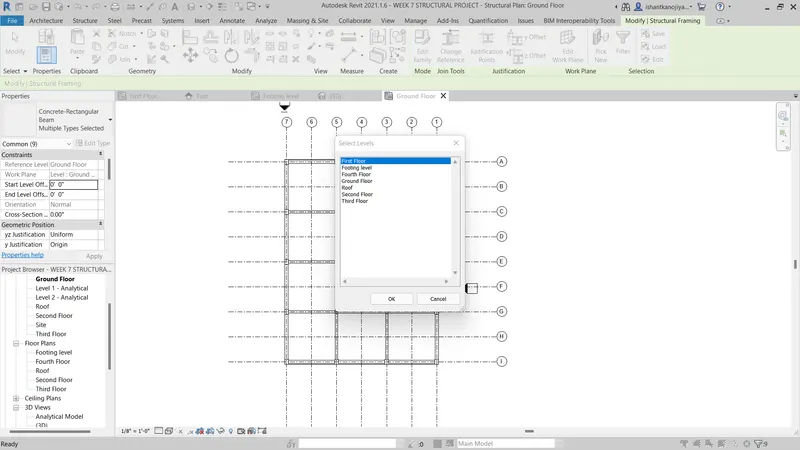
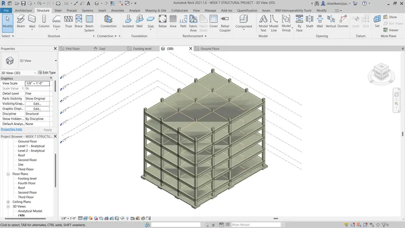
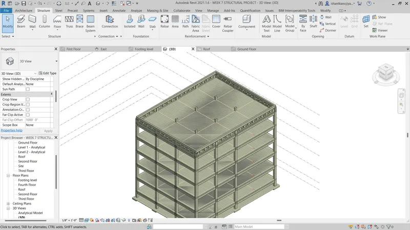
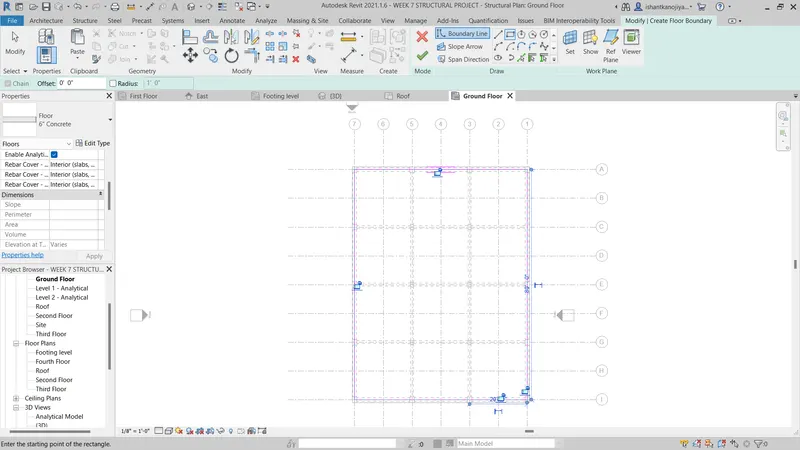
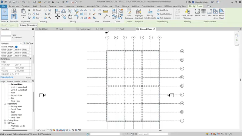
- SELECT FLOOR >SELECT COPY > GOTO ALIGNED TO LEVELS> SELECT LEVELS PRESS OK
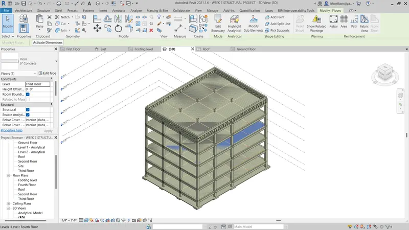
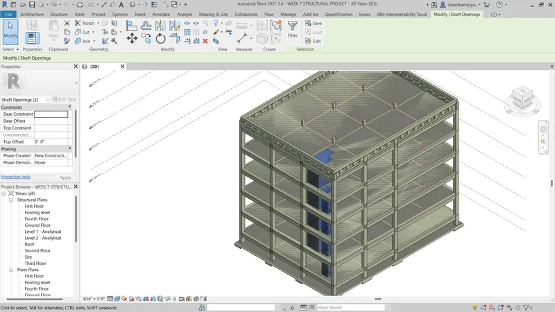
- SELECT SHAFT IN STRUCTURAL TOOL BAR> SKETCH SHAFT BOUNDARY AS PER YOUR CONVENIENCE
- SELECT FIRST FLOOR TO ROOF LEVEL IN PROJECT BROWSER
The architectural model, include the following components based on the type of structure selected
a. Wall Layout with appropriate material and finishing
b. Exterior façade with fancy finish
c. Interior partition walls to size rooms
d. Components to add details to a room ( Desk, Chair, Lighting, Plumbing fixtures)
e. Add components such as stairs Elevators
f. Have at least one side of the building with curtain walls and glass panels
g. Include interior and exterior lighting fixtures
h. Place proper topographic components from outside ( Trees, Parking, Plants) to add details to the model
PROCEDURE:-
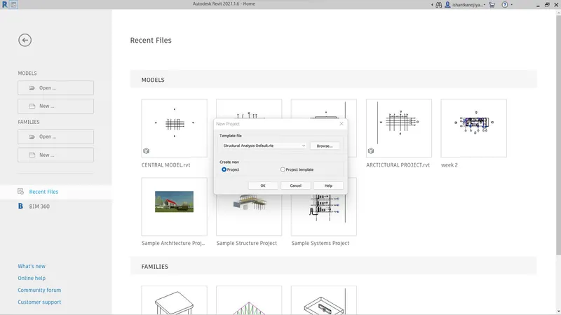
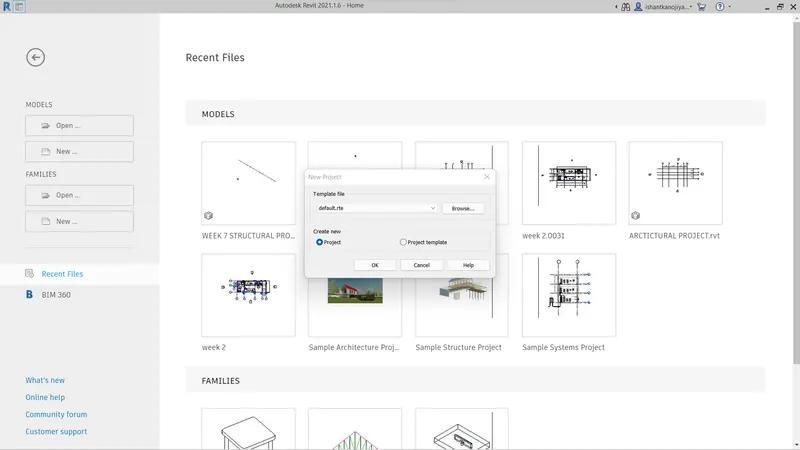
- SELECT NEW PROJECT> SELECT IMPERIL ARCHITECTURE TEMPLATE> PRESS OK
- GOTO MANAGE TOOL BAR> SELECT MANAGE LINKS> SELECT FILE(WEEK7 STRUCTURAL PROJECT)> SELECT LOAD >PRESS OK
- SELECT COPY MONITORING TOOL (FOR PLACING LEVELS AND GRIDS)> SELECT LINK OPTION> SELECT STRUCTURAL AREA> THEN SELECT ONE BY ONE EVERY GRIDS AND LEVELS
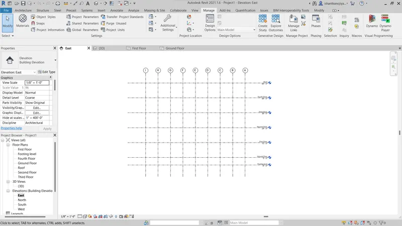
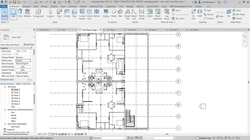
- SKETCH PARTITION WALLS
- SELECT ARCHITECTURAL WALL > SELECT TYPE OF WALL> 12' GENERIC WALL
- TOP OFFSET -2'8"
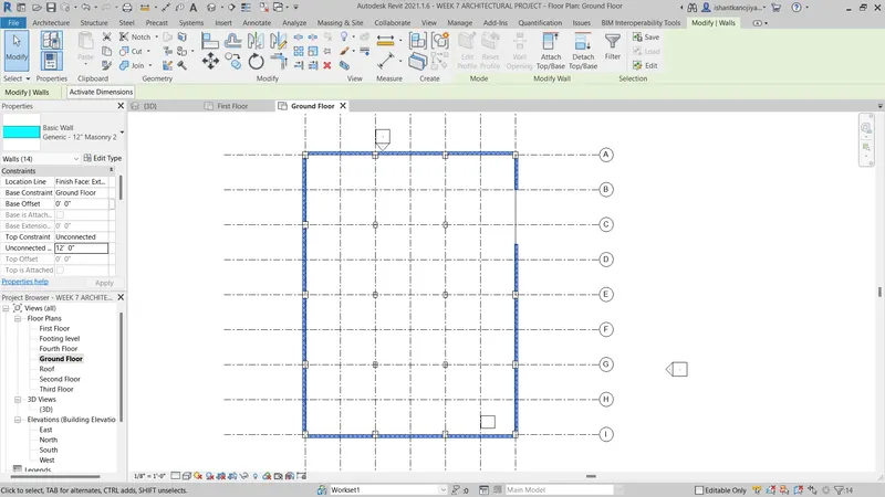
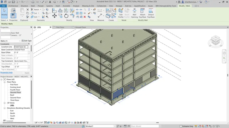
- SELECT STAIR CASE> SELECT STAIR TYPE> SELECT START POINT> THEN GIVE LANDING> THEN ENDPOINT > PRESS OK
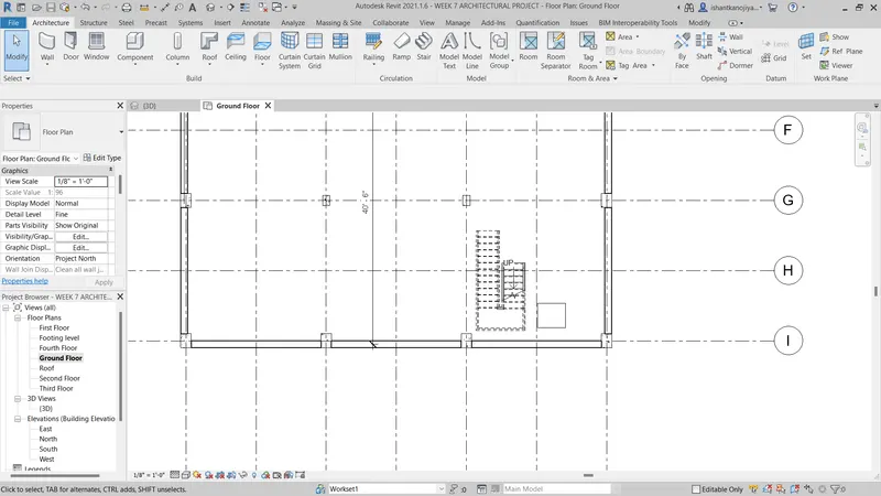
- parking
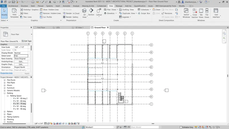
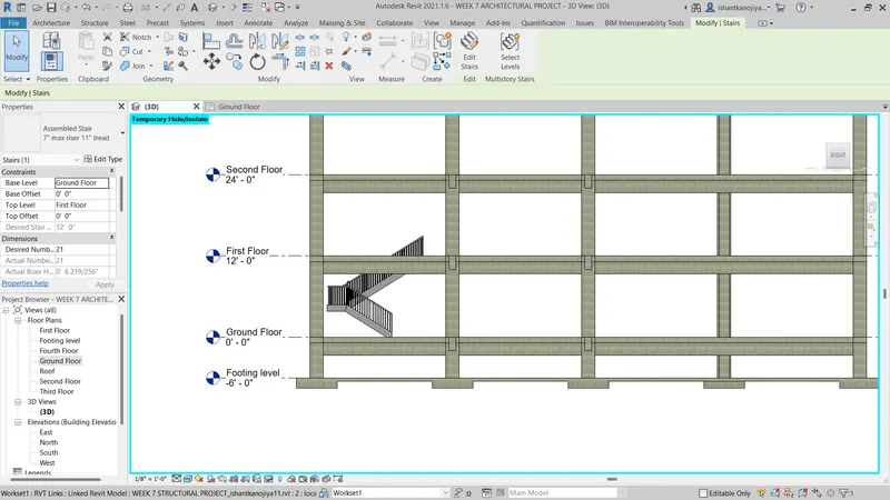
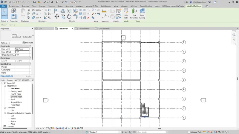
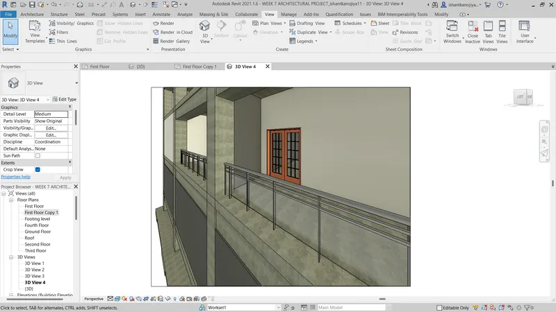
- SKETCHING WALL, AND RAILING
- GOTO FIRST FLOOR
- SELECT ARCHITECTURAL WALL> SELECT 6" GENERIC WALL > ADJUST SOME SETTING (LIKE HEIGHT, TYPE AND THICKNESS )> SELECT PATH WHERE YOU PLACED WALL > PRESS OK
- SELECT RAILING> SELECT TYPE OF RAILING> SPECIFY WHERE YOU REQUIRED/ SKETCH THE LINE > PRESS OK
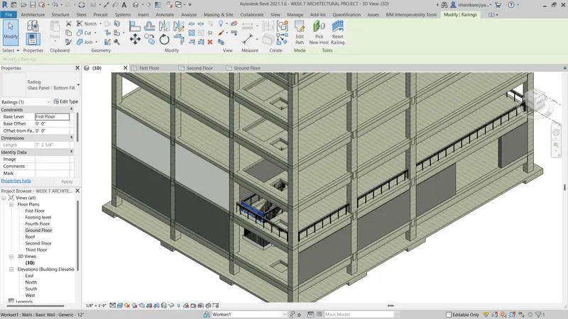
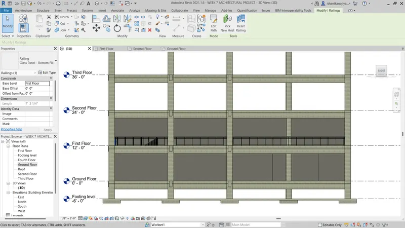
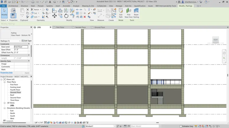
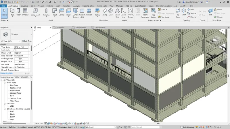
- sketching curtain walls
- select architectural walls> select curtail wall> select start point to end point> press ok
- then select curatil grids> select curtail wall> specify spacing b/w grids(2'horizontal and 4'vertical)> press ok
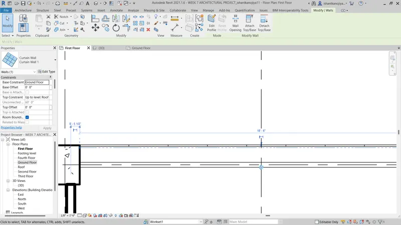
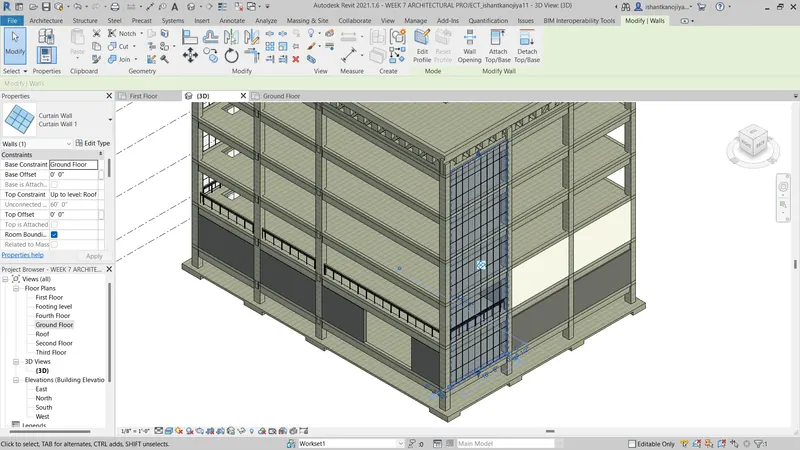
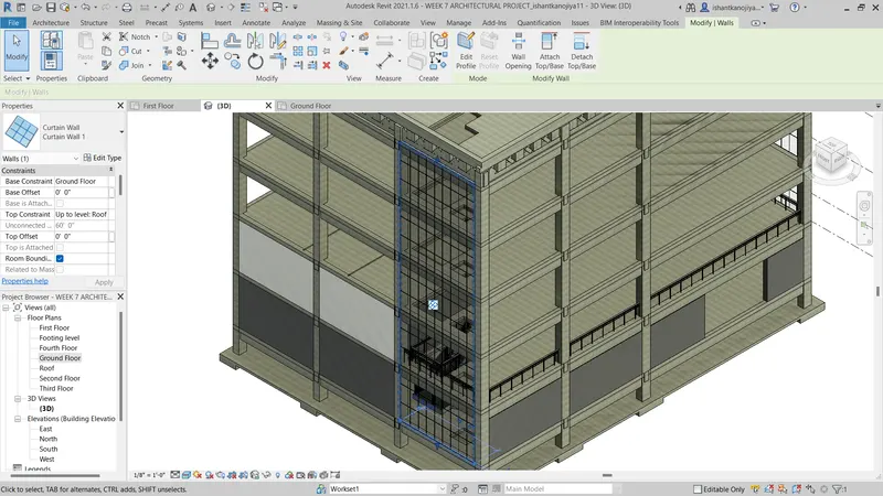
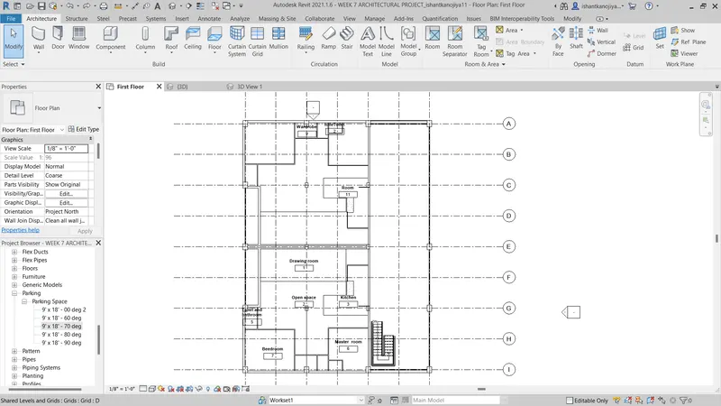
- select components in architectural tab > select components like chair, table, beed and other elements
- select element > specify size and and material> select location > press ok
- palcing doors
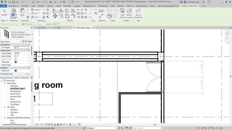
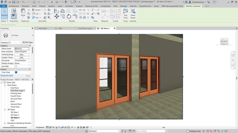
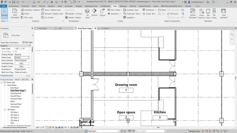
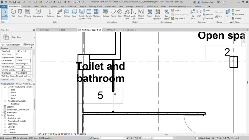
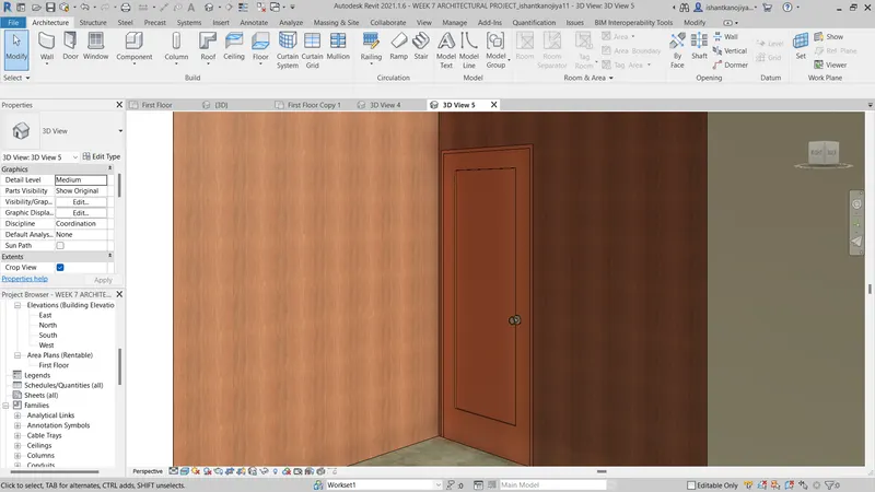
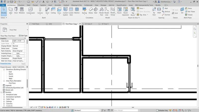
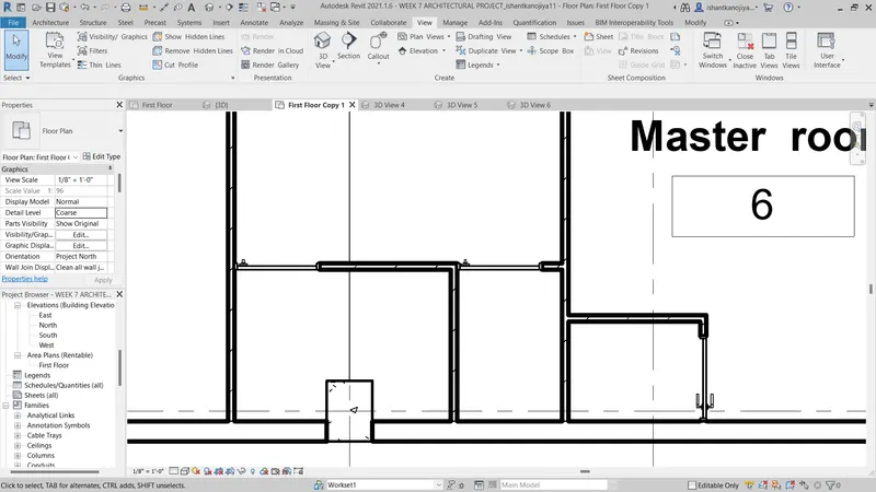
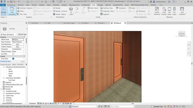
- Placing windows
- select windows in architectural tool bar> select type nad size of windows> speify height to floor > palced where you required
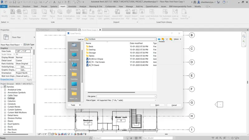
- if windows family is not present in properties > so go to insert tool bar> select load family> select windows floder> select types of faimily element required > press ok > select size of wlwment> presss ok
-
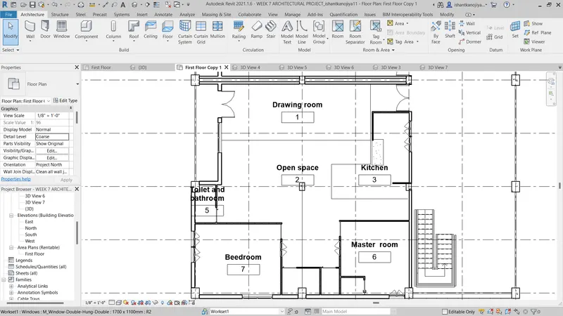
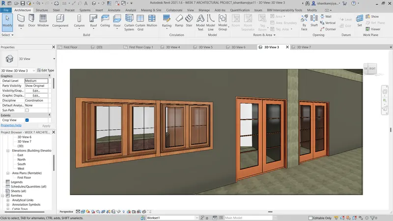
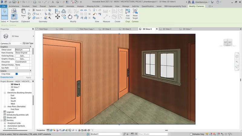
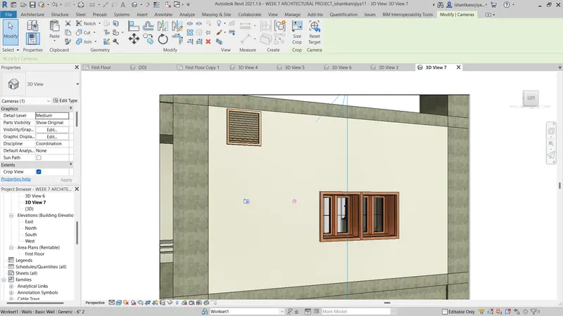
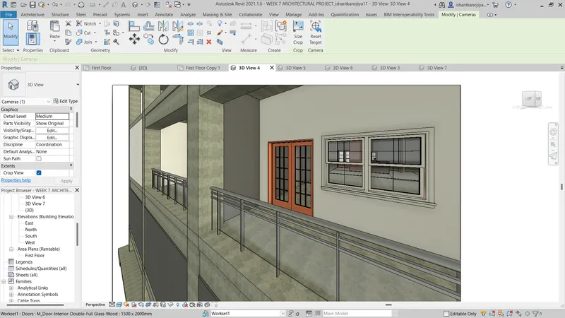
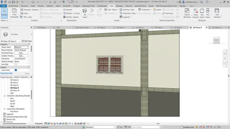
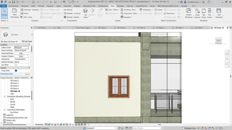
- select components like windows doors > select mirror axix> specify axix press ok
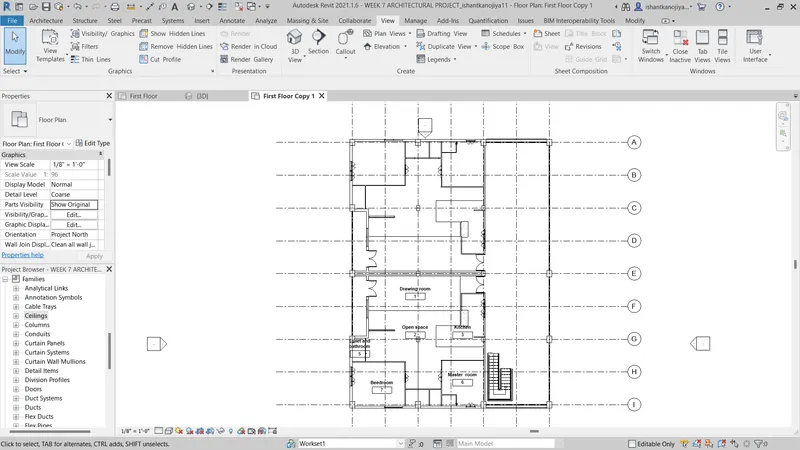
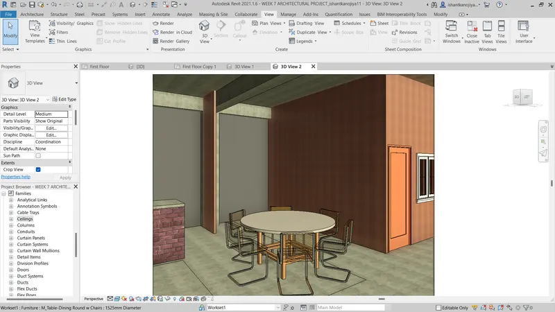
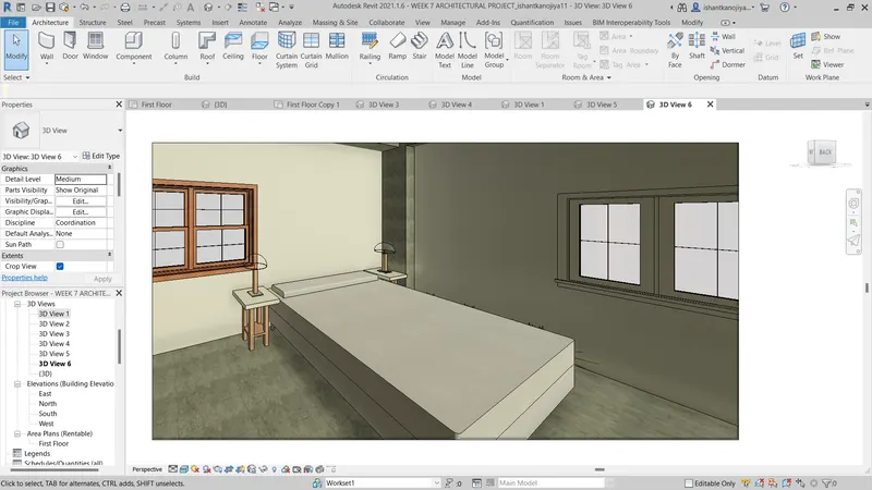
- Placing bed,table, chair and other components
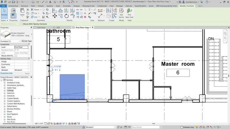
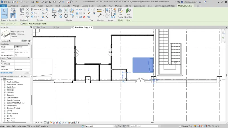
- select component in architectural tool bar> go to bed > select size and type > specify side> press enter
- If bed family is not show > goto insert >select load family> goto furniture> select bed folder> select size and type of bed > press enter
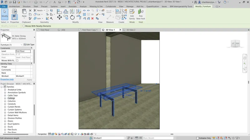
- TV,TV stand, and sofa
- select tv family > select 1270mm size > select first level > specify height of level 5' > press ok
- select chair family > select sofa > select size and type (as shown in snip)> specify location > placed it
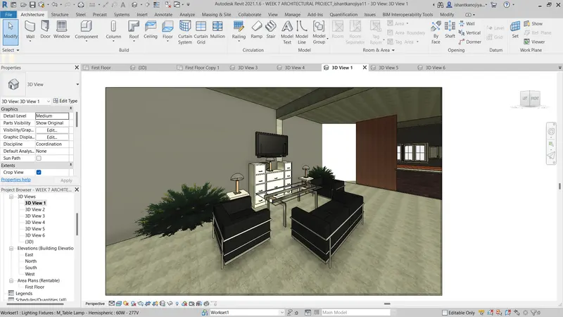
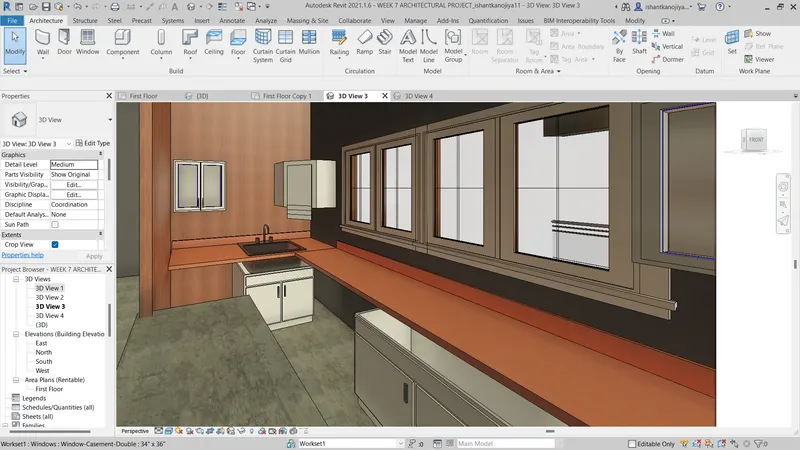
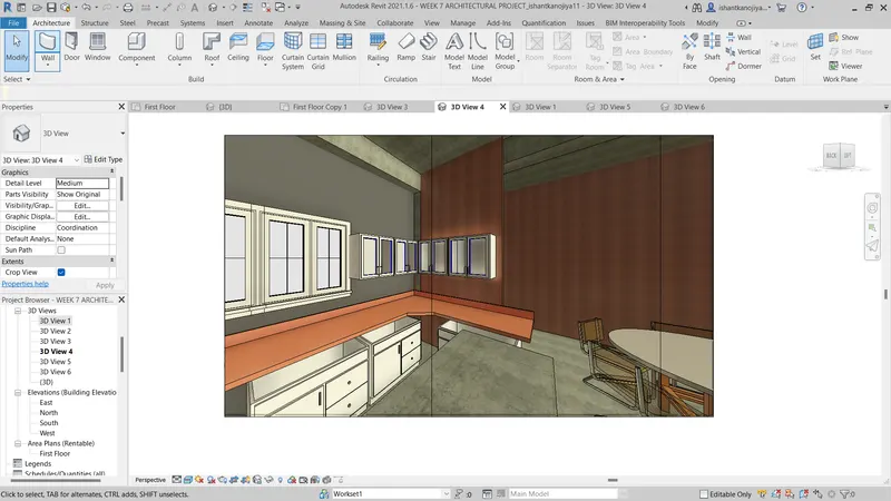
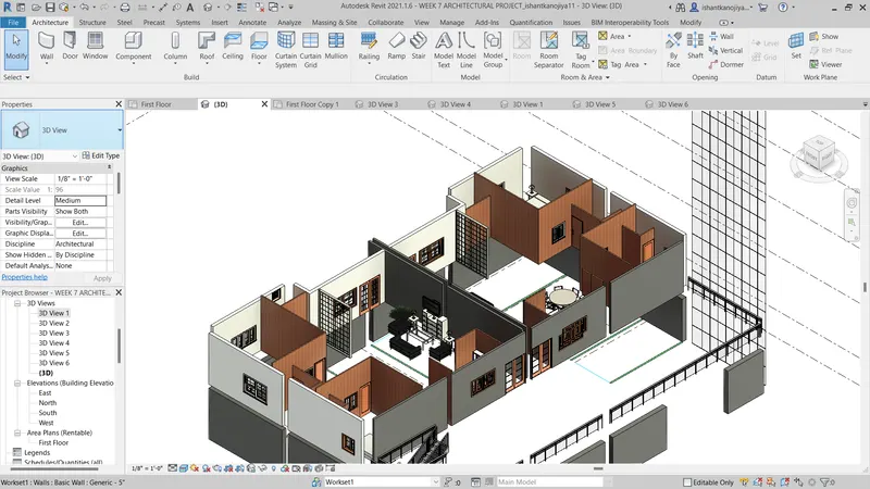
- Placing lighting fixture
- Placing paint on the walls
- first, go to manage tool bar> select material> create paint as a material> specify parameters as per requirement> then go to modify tool bar> select paint option > select material/paint> select face of wall > press enter
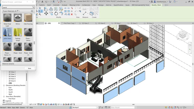
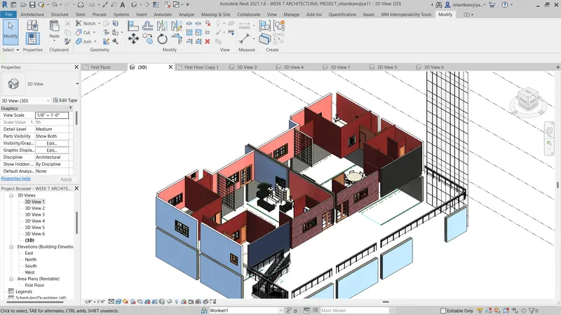
- select copy tool > select all elements > select aligned to levels > select levels, second,third, forth> press enter
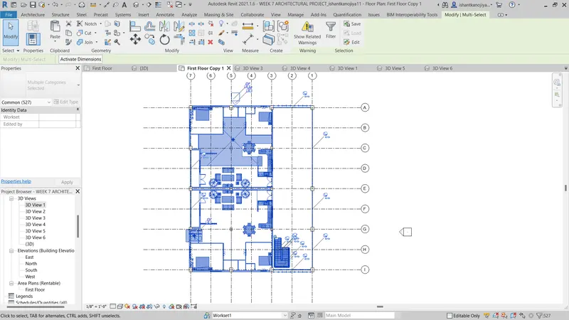
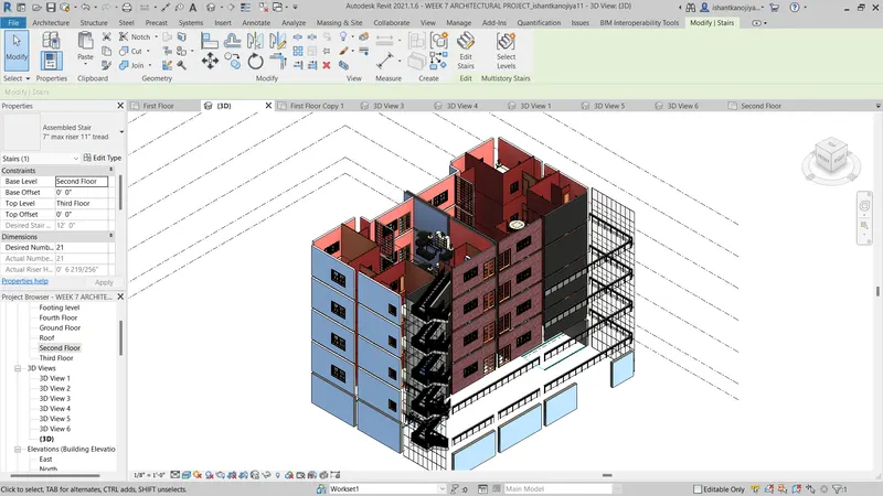
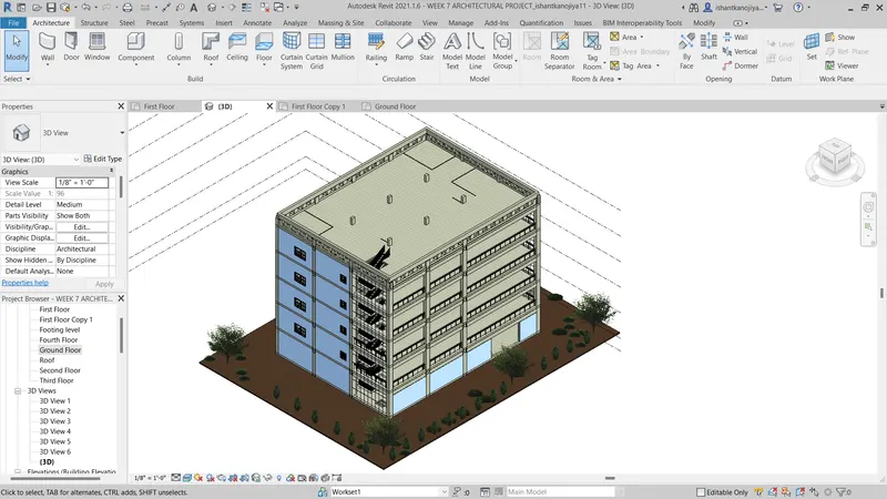
Provide a set of drawings in an architectural and structural model to list the following details with categories and appropriate sheet templates included
a. Floor Plans with Annotations
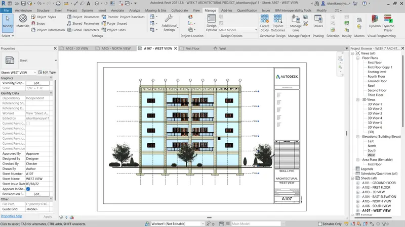
b. Elevations
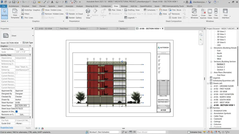
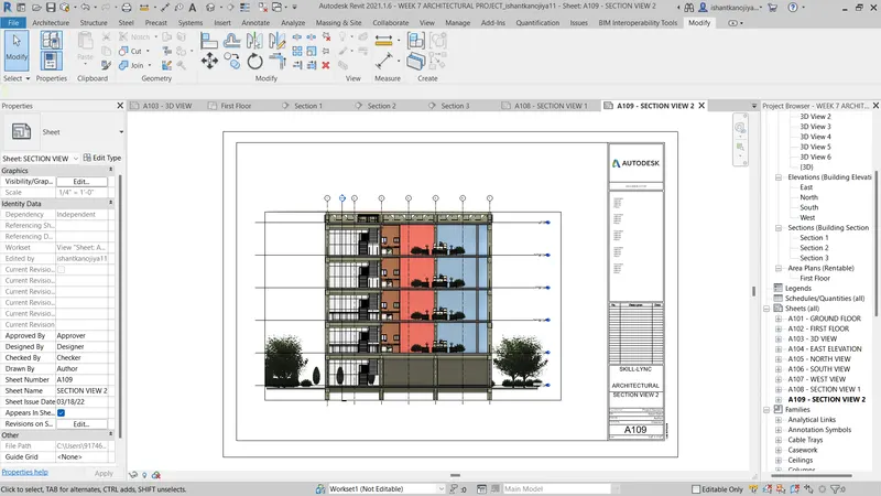
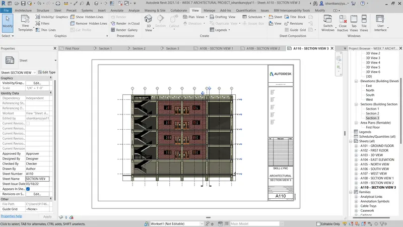
c. Sections
STRUCTURAL MODEL
- FLOOR PLANS WITH ANNOTATIONS
- GO TO WEEK7 STRUCTURAL PROJECT
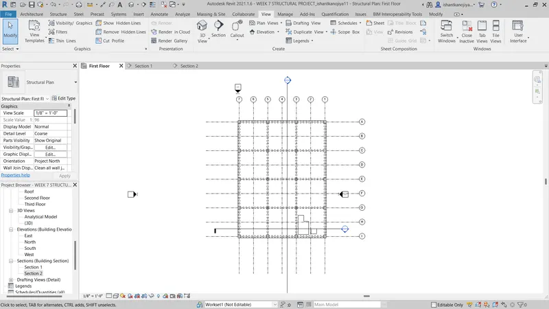
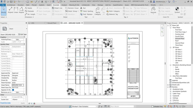
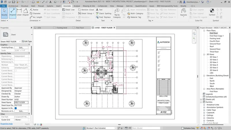
- GO TO FLOORS PLANS LIKE FOOTING LEVEL, GROUND FLOOR, FIRST FLOOR, AND ROOF LEVEL
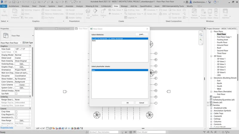
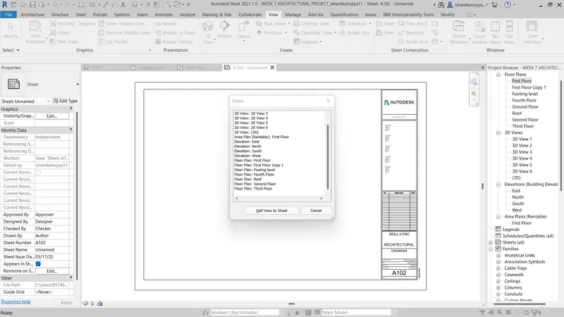
- GOTO VIEW TOOL BAR> SELECT SHEET > SELECT A4 SIZE SHEET >SELECT VIEWS / DRAG AND PALCED INTO SHEET
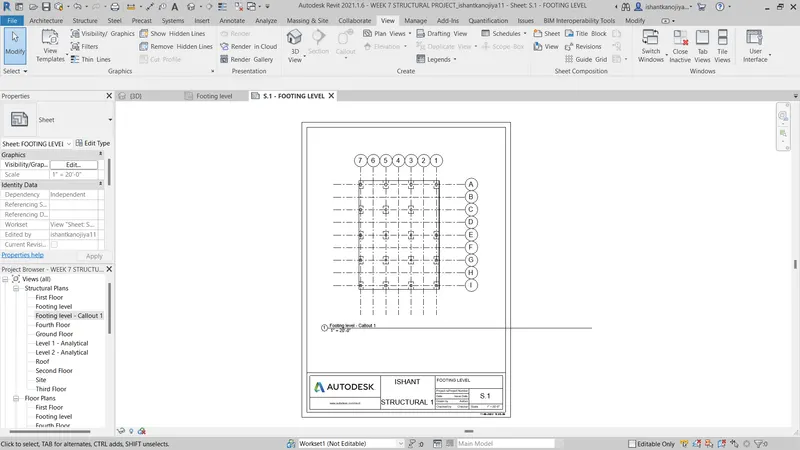
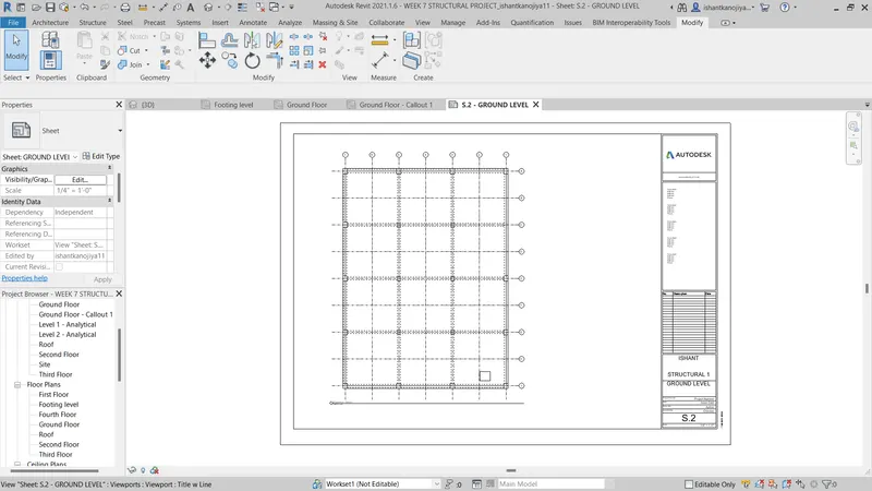
- GOTO ELEVATION IN PROJECT BROWSER > SELECT EAST, WEST, NORTH, SOUTH> DRAG THE CURSOR INTO SHEET > SPECIFY POINT AND SCALE AS PER YOUR REQUIREMENT> EDIT NAME > PRESS OK
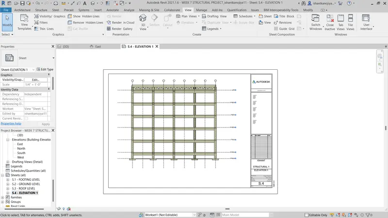
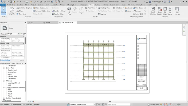
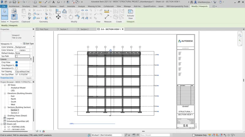
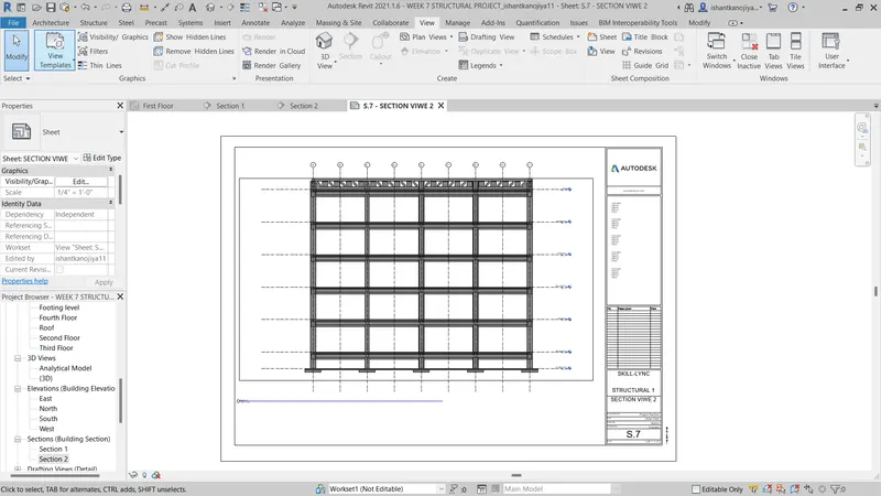
- GOTO VIEW TOOL BAR> SELECT SECTION> SELECT START POINT AND THEN ENDPOINT TO PLACE SECTION VIEW > WHEN VIEW IS CREATED > THEN CREATE SHEET > THEN GOTO PROJECT BROWSER > SELECT SECTION VIEW> DRAG THE CURSOR INTO SHEET > SPECIFY POINT AND SCALE > RENAME > PRESS OK
- PLAN VIEW
-
ARCHITECTURAL MODEL
- SAME AS STRUCTURAL MODEL
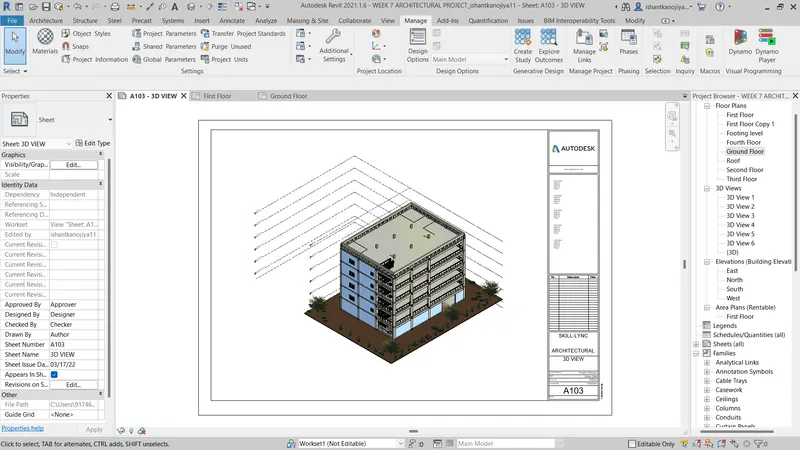
- ELEVATION VIEWS
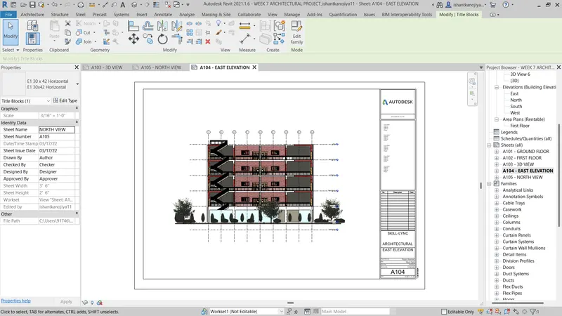
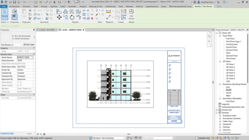
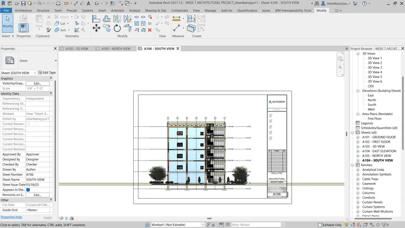
- SECTION VIEWS
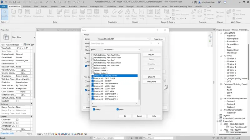
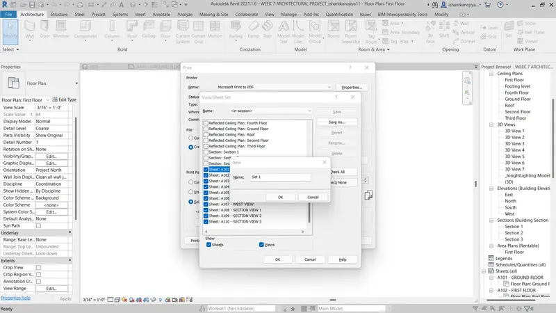
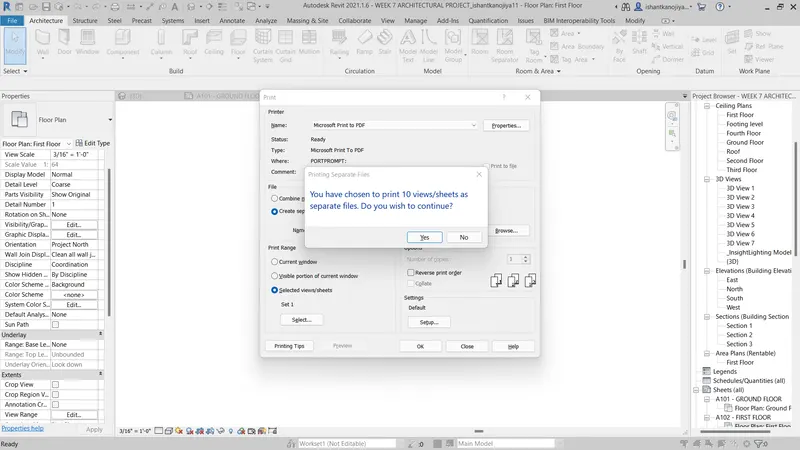
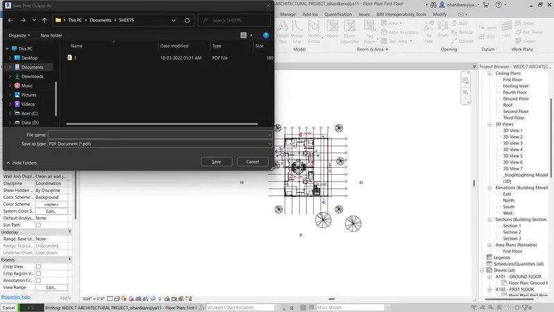
- SELECT PRINT OPTINO> PRINT TO SHEET AND VIEW > SELECT VIEW AND SHEETS>PRESS OK

RESULT
- FIRSTLY SKETCH STRUCTURAL MODEL
- SPECIFY COORDINATES AND COLLABORATE WITH CENTRAL MODEL
- THEN SECOND SKETCH ARCHITECTURAL MODEL
- SPECIFY COORDINATES AND COLLABORATE WITH CENTRAL MODEL
- THEN SKETCHING IN STRUCTURAL MODEL AS PER DRAWING SHOWN IN SNIP
- THEN SKETCHING ARCHITECTURAL DRAWING AS PER DRAWING SHOWN IN SNIP
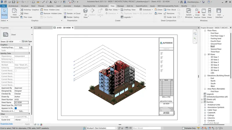
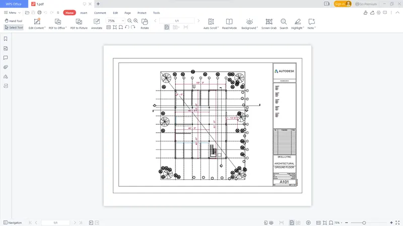
- THEN CREATING SHEETS AND VIEWS BOTH STRUCTURAL AND ARCHITECTURAL
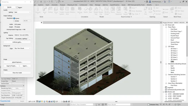
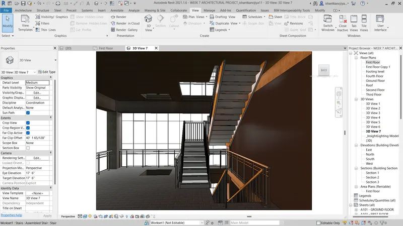
- THEN RENDERING THE MODEL
- THEN PRING THE SHEETS INTO PDF FORM WHICH IS UPLOADED