Creating a Wardrobe detailed drawing, Floor Plan, Kitchen Layout and Column Detail using AutoCad
-
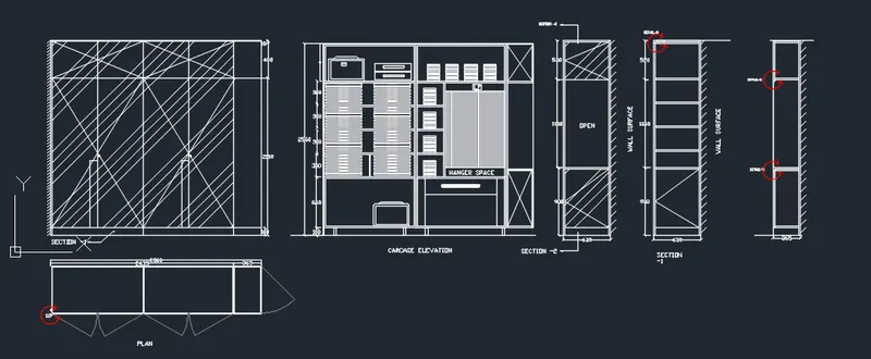
AIM & INTRODUCTION : To draw the elevation and details of a wardrobe by using auto cad as shown in the Figure below.along dimensions and text with the use of layers.
Note: All dimensions are in mm.
Start with New drawing file
Set the units in millimetre
Set dimensions size 50mm text size as 50mm
PROCEDURE :
-
- Sketching a plan :
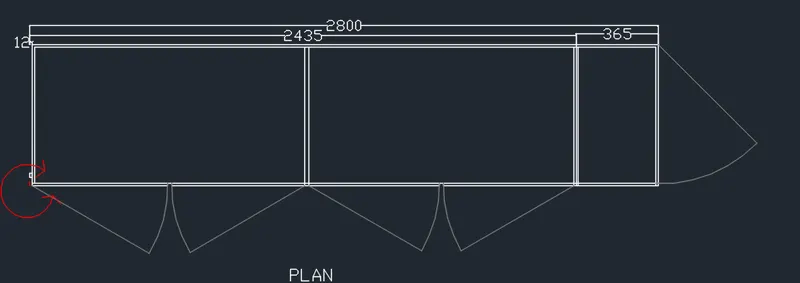
- Draw a rectangle of dimensions 2800,630 by using “REC" command in command prompt
- Offset of 12 mm inside to the rectangle by using command "O" > enter >Enter distance as 12 > specify Object: select rectangle > select inner side of rectangle.
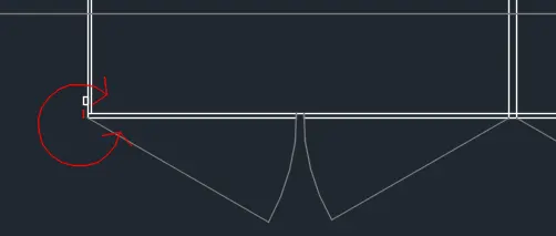
- Drew a rectangle on left side inside of the wall with dimension 20mm, 20mm
- Explode the rectangle Command "EXPLODE" - select the rectangle - enter.
- Create Offset of vertical lines of plan according to given dimensions 2435mm and 365 mm from right side of the rectangle
- Provide the thickness of 20mm where ever it necessary by using “OFFSET” command
- Trim the Unwanted lines by using of “TRIM” command
- For doors draw line with the help of line command the required dimension should be divided in to equal parts of given dimension
- Rotate the line in 45 angle by using “RO” command and Draw the arc between corner of the door and rest position of the Wardrobe.
- Provide dimensions with Dimension tools like dimension linear and dimension angular.
- Provide text by using LEADER, DTEXT and MTEXT command
- Drawing a front elevation :
- Draw a rectangle of 2800mm,2600mm dimension
- By using “OFFSET “command offset the rectangle at distance 12mm
- Draw the lines as per dimensions given by using “LINE”,” OFFSET”,” TRIM” commands.
- Hatch the required area by using “HATCH” command and the pattern is ANS134
- Provide dimensions with Dimension tools like dimension linear and dimension angular.
- Draw a line of 50 inclined at 45 angle to the vertical line and spread by using ARRAY command
- ARRAY> select object >PATH> Set distance of 40mm
- Provide text by using LEADER, DTEXT and MTEXT command
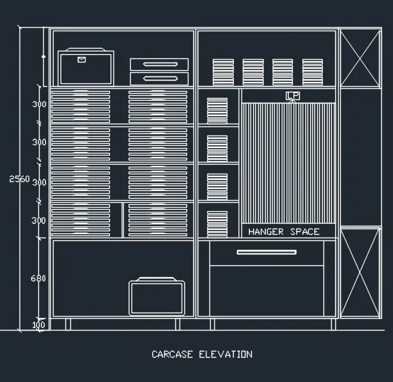
3.Drawing Carcase elevation:
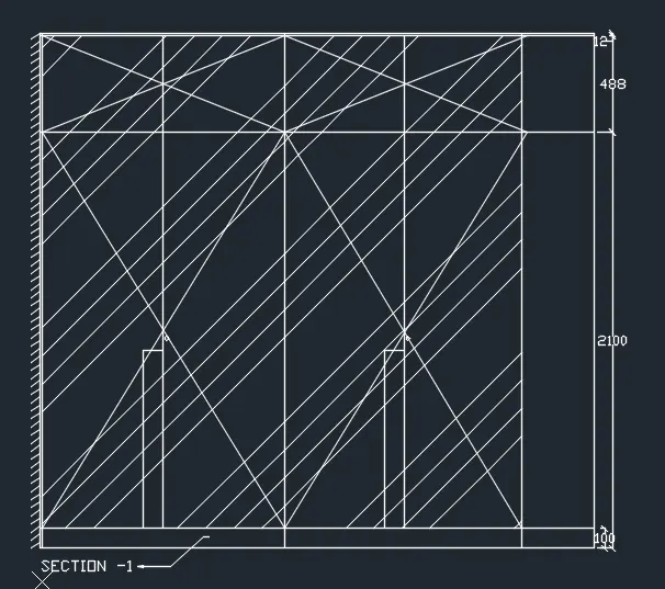
- Project the lines to side from the elevation - bottom line, offset 100mm line ,2100mm line from the bottom and 12 mm thickness.
- Draw dimensions of objects in the car case Elevations drawing has been assumed and drawn.
- Provide dimensions with Dimension tools like dimension linear and dimension angular.
- Draw a line of 50 inclined at 45 angle to the vertical line and spread by using ARRAY command
- Provide text by using LEADER, DTEXT and MTEXT command
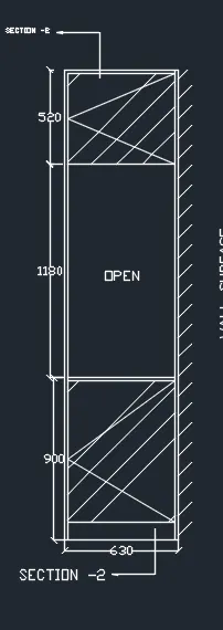
- Side elevation:
- Project the height of the carcase with XL command.
- Draw a line of 630mm on both left and right sides
- The thickness of 20mm is given by “OFFSET” command
- Draw the lines as per dimensions given by using “LINE”,” OFFSET”,” TRIM” commands.
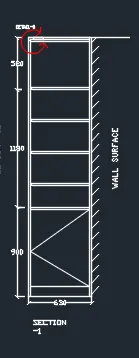
5.Section 1
- Project the height of the elevation
- Offset of 630mm which is the width and provide an offset of 20mm for thickness.
- For the inside cabinets project lines from the carcase elevation of 100mm,900mm,300mm and 20mm as thickness .
- Trim the unwanted lines by trim command
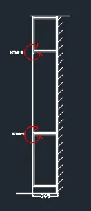
- Section 2
- Project the height from the side elevation as the section is taken from the side elevation.
- Provide offset of 365mm & 20mm on the sides and top.
- Provide offset Project the 900mm line from bottom and 520mm line from the top
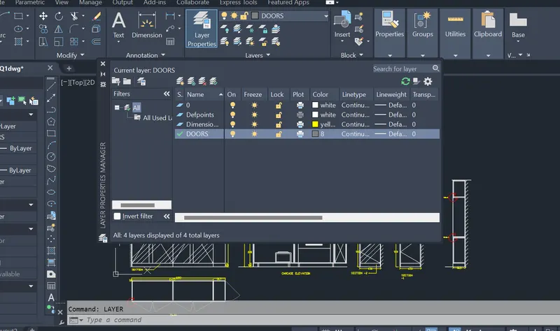
Layers: Create a layers of Doors , dimension,Hatches and place accordingly
RESULT:
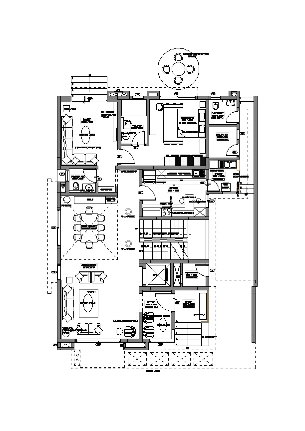
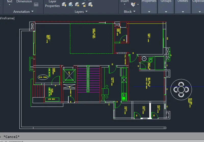
- AIM & INTRODUCTION : Draw the floor plan as shown in the Figure BY USING AUTO CAD.
Note: All dimensions are in mm
Walls (Exterior and Interior)
Wall Thickness: Exterior Wall- 230mm, Interior Wall: 150 mm (Wherever Required)
Doors and Windows: Assume the size of the doors and window.
Stairs: Tread-300mm, Riser-150mm
Insert Text wherever require
Insert the dimensions using proper dimension techniques.
PROCEDURE:
TOOLS USED :
- CONSTRUCTION LINE
- LINE AND POLYLINE
- RECTANGLE
- CIRCLE
- ARC
- TRIM
- OFFSET
- MEASURE
- DIMENSION ALINEAR
- LAYERS
1. CREATING WALLS OF ROOMS WITH THICK NESS DEPENDS UP ON WALL:
- Create XL-line at vertical direction and horizontal direction.
- Offset the wall thickness according to wall size with the help of OFFSET command
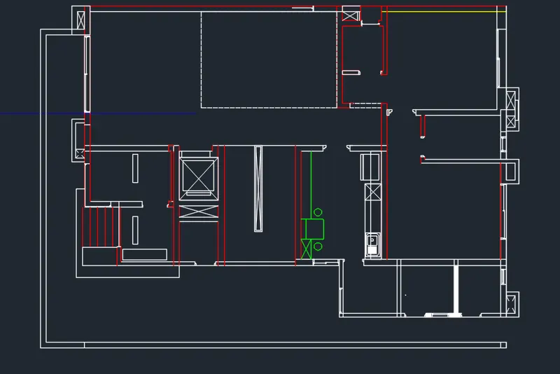
- Create the ventilator, door and window frames according to size with the help of acr,line, trim commands.
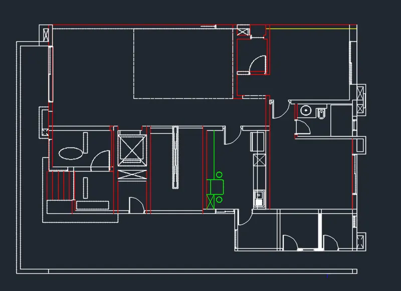
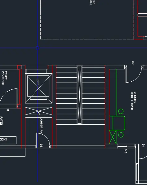
- Draw the stair case according to size. LINE and ARRAY commands are used
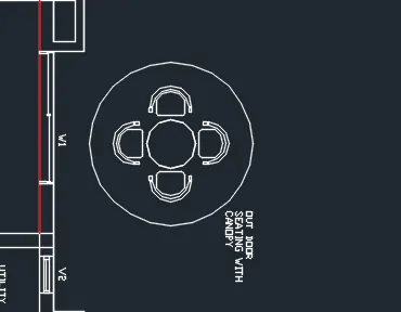
- Draw the canopy according to dimensions.
- Text the areas requires with the help of MTEXT command
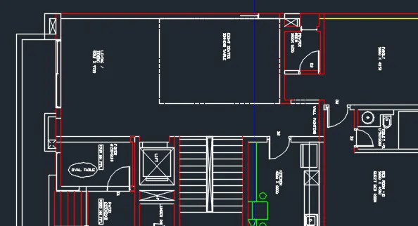
- MT> specify point: select the area of a point > Angle: 0> Enter text to be display
- Repeat the above following text command shown above
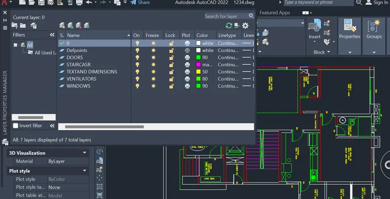
- Separate in to layers
Result:
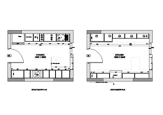
Q3. AIM & INTRODUCTION : To create the Kitchen Layout as shown in the Figure below. Also, use proper dimension techniques to dimension the kitchen layout. Also, insert text wherever required.
All dimensions are in mm.
Procedure:
- Open new drawing file
- Set units in millimmeter
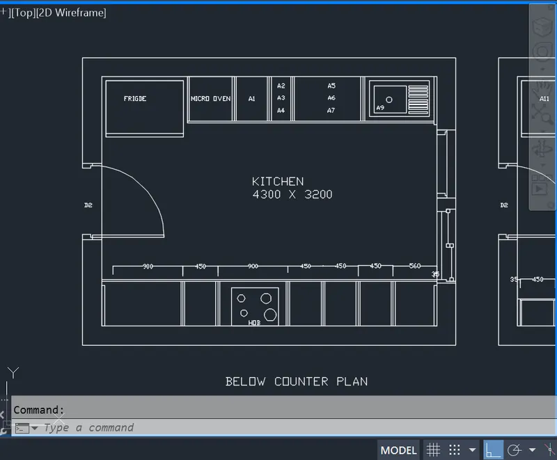
1.Creating a below counter plan:
- Draw a rectangle of 4300 mm,3200mm by using Rectangle command
- Rectangle >Specify first point > dimenstion >4300,3200 > Enter
- OFFSET > ENTER > 245 > select rectangle > select inside of the rectangle.
- Create doors , windows and objects by using LINE, OFFSET, CIRCLE and RECTANGLE command.
- Provide required dimensions with the help of "DIMENSION LINEAR" option
- Place a text by using DTEXT command
2.Creating above counter plan:
- Draw a rectangle of 4300 mm,3200mm by using Rectangle command
- Rectangle >Specify first point > dimenstion >4300,3200 > Enter
- OFFSET > ENTER > 245 > select rectangle > select inside of the rectangle.
- Create doors , windows and objects by using LINE, OFFSET, CIRCLE and RECTANGLE command.
- Provide required dimensions with the help of "DIMENSION LINEAR" option
- Place a text by using DTEXT command
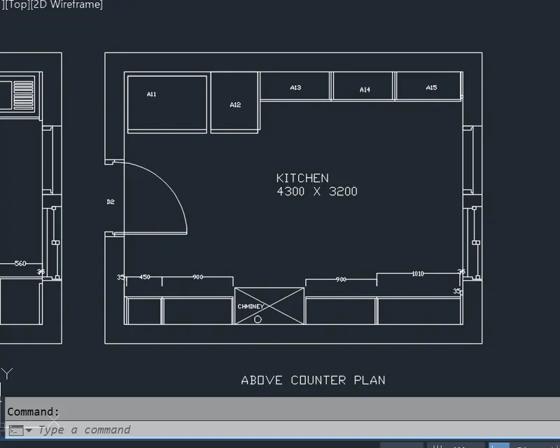
RESULT:
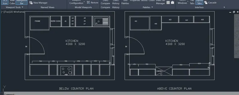
AIM & INTRODUCTION :
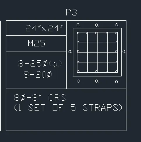
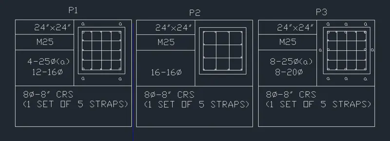
AIM & INTRODUCTION : To create the column details by using auto cad as shown in Figure.The bar size is refered as per sechdule.
Where ,
- 8mm ---- 0.31 Inches
- 25mm--- 1 inches
- 16mm—0.62 inches.
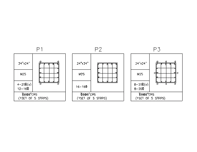
Procedure:
- Open new drawing file
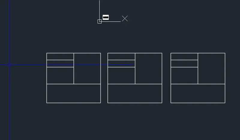
- Set units in feets
- draw a rectangle of 8' and 6' by using rectangle command
- divide in to 2 parts vertically and 3 parts horizontal direction by using divide command
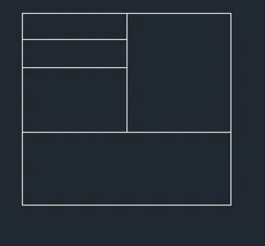
- copy the entire table at 10' away from specific point as shown in figure below
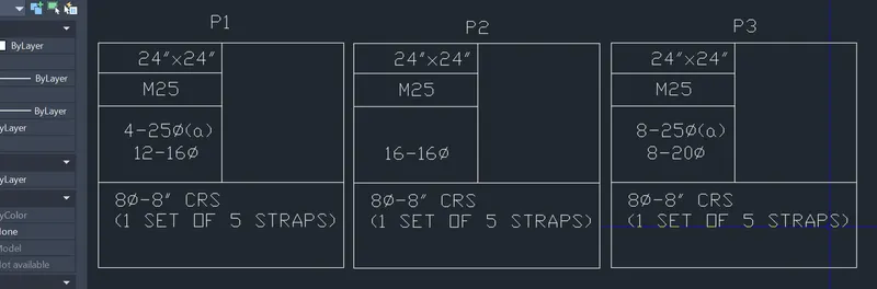
- By using Mtext commandfill the text in table as shown in figure
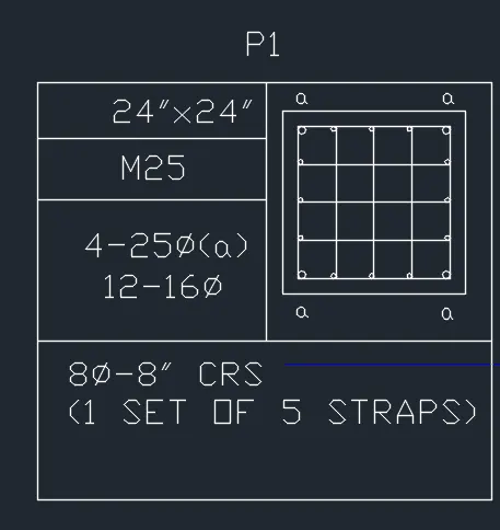
- Creating a P1 reinforcement by using details in the table
- Crearte a rectangle of 24" x 24" by using Rectangle command
- Off set the rectangle in to inwards to the selected rectangle.
- Make a circle by using corner tangents of inner rectangle at four sides of the inner rectangle.
- Circle > TTR > select the sides of rectangle > Enter radius > 1" >Enter.
- Apply the abovecircle step at four corners
- Explode the inner rectangle with the help of explode command
- Explode > select the Object : select the inner rectangle > Enter
- Divede the Inner rectangle by using rectangle command 3 parts of horizontal and 3 parts of vertical by using divide command
- Div > select the object : select the verticall ine > Enter the number of segment as 3
- Apply the above command for horizontal line of rextangle.
- Make circle at the corners of the inner rectangle
- Circle > TTR > select the sides of rectangle > Enter radius > 0.31" >Enter.
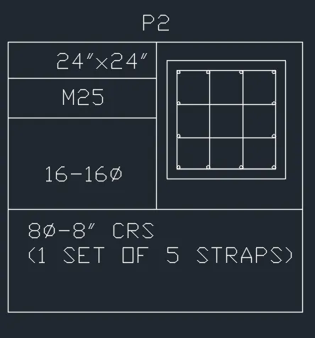
- Creating a P2 reinforcement by using details in the table
- Crearte a rectangle of 24" x 24" by using Rectangle command
- Off set the rectangle in to inwards to the selected rectangle.
- Make a circle by using corner tangents of inner rectangle at four sides of the inner rectangle.
- Circle > TTR > select the sides of rectangle > Enter radius > 0.31">Enter.
- Apply the abovecircle step at four corners
- Explode the inner rectangle with the help of explode command
- Explode > select the Object : select the inner rectangle > Enter
- Divede the Inner rectangle by using rectangle command 3 parts of horizontal and 3 parts of vertical by using divide command
- Div > select the object : select the verticall ine > Enter the number of segment as 3
- Apply the above command for horizontal line of rextangle.
- Make circle at the corners of the inner rectangle
- Circle > TTR > select the sides of rectangle > Enter radius > 0.31" >Enter.
- Creating a P3 reinforcement by using details in the table
- Crearte a rectangle of 24" x 24" by using Rectangle command
- Off set the rectangle in to inwards to the selected rectangle.
- Make a circle by using corner tangents of inner rectangle at four sides of the inner rectangle.
- Circle > TTR > select the sides of rectangle > Enter radius > 0.31">Enter.
- Apply the abovecircle step at four corners and four mid points of rectangle
- Explode the inner rectangle with the help of explode command
- Explode > select the Object : select the inner rectangle > Enter
- Divede the Inner rectangle by using rectangle command 3 parts of horizontal and 3 parts of vertical by using divide command
- Div > select the object : select the verticall ine > Enter the number of segment as 3
- Apply the above command for horizontal line of rextangle.
- Make circle at the corners of the inner rectangle
- Circle > TTR > select the sides of rectangle > Enter radius > 0.31" >Enter.
RESULT:
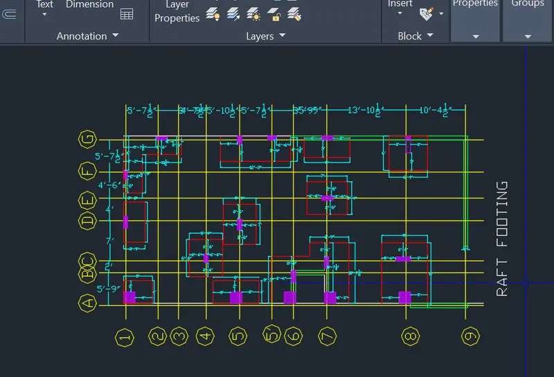
AIM & INTRODUCTION : To Draw the Raft Layout by using auto cad as shown in the Figure.
Hint: missing dimensions are assumed or it can be known by importing the pdf in to auto cad
Procedure:
Command used
- Line
- Rectangle
- Offset
- Mtext
- Dimension Aligned
- Trim
- Layer
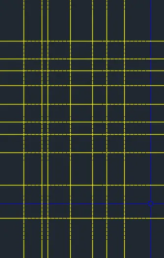
1. Creating a center line by using XL xommand and offset in to multiple lines according to dimensions at both horizontal and vertocal directions.
Example : XL> vertical ,enter> specify the point: select the area
Offset the ine in 5'9" from the exsisting line
Offset > Specify the Distance >5'9" > select the exsisting line > select the direction to offset : Right side.
Apply the above command as dimensions are provided in figure
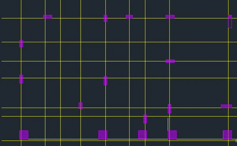
2. Creating a column by using the Rectangle command as per dimensiond shown in figure
As dimensions are not been provided
attach the pdf in auto cad and scale it
Hatch the columns by using Hatch command
3. Creating a Foundation (RCC) command as per dimensiond shown in figure
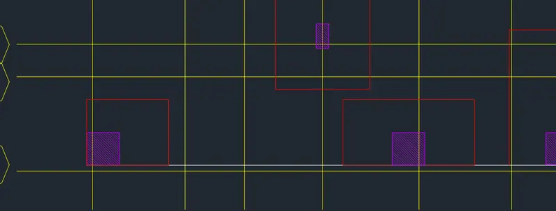
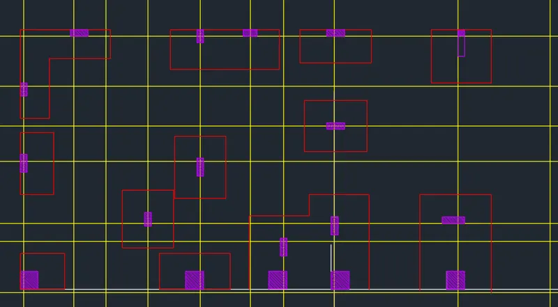
4. Creating a wall by using line, offset and trim command.
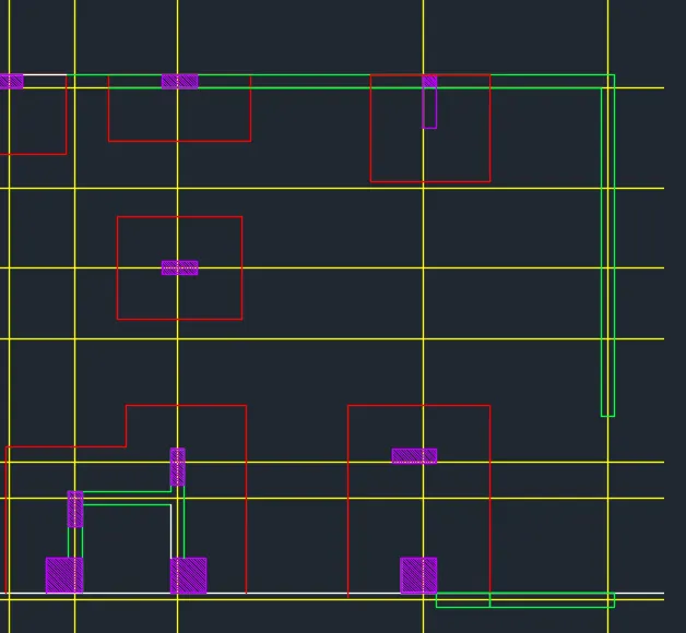
.
5.Provide dimensions required by using DLI command or linear Dimension tool.
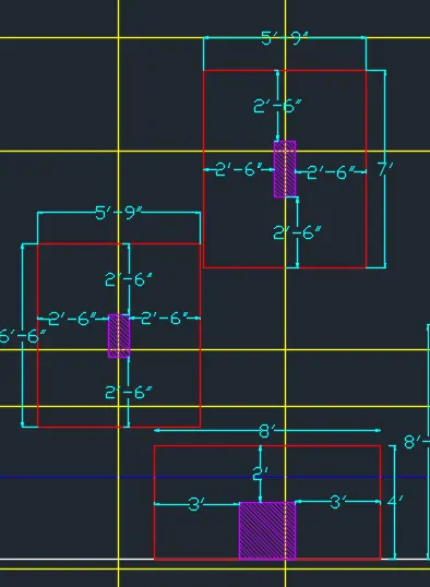
6. Place text required by using DTEXT and MTEXT command.
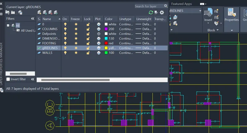
7.Arrange in to diffrernt layres as per requirmeny by using layer command
LA > CREATE A NEW LAYER > NAME THE LAYER > SELECT THE OBJECT > SELECT THE LAYER WANT TO MOVE THE OBJECT
RESULT: