Creating a Wardrobe detailed drawing, Floor Plan, Kitchen Layout and Column Detail using AutoCad
1. WARDROBE ELEVATION AND DETAILS
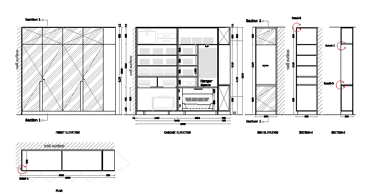
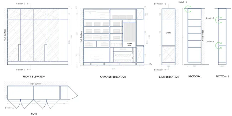
Aim: To Draw the elevation and details of a wardrobe as shown in the Figure above. After sketching and to provide the dimensions and text with the use of layers.
Introduction:
The Wardrobe detailed drawing is created in AutoCAD using the draw tools and after sketching, the dimensions and text are provided with the use of Layers. The procedure of drawing is explained and the final result is given.
Procedure:
Step 1
Type unit or UN in the command line and press enter
Set type of unit as decimal and precision as 0
In insertion scale set unit as millimeter.
Step 2
Type layer or LA in the command line and press enter
Create new layers as per requirement
Step 3
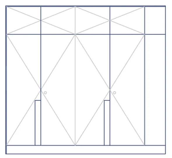
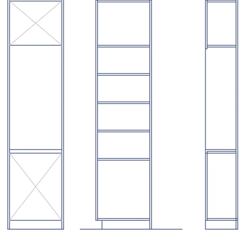
Using line tool and offset tool draw the front elevation of the wardrobe as per the given dimensions
Step 4
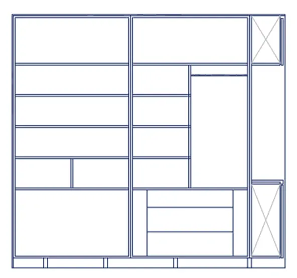
Using draw tools and offset draw the carcase elevation of the wardrobe
Step 5
Using draw tools and offset draw the side elevation and sections of the wardrobe
Step 6
Using hatch command, dimension command and text command complete the elevation, section and other details of the wardrobe
RESULT
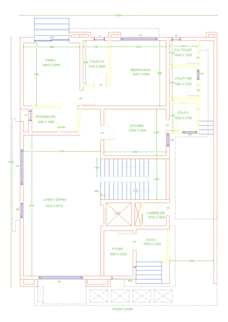
2. FLOOR PLAN
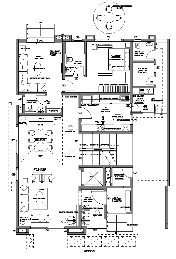
Aim: To Draw floor plan as shown in the Figure above. After sketching and to provide the dimensions and text with the use of layers.
Introduction:
The Floor plan detailed drawing is created in AutoCAD using the draw tools and after sketching, the dimensions and text are provided with the use of layers. The procedure of drawing is explained and the final result is given.
Procedure:
Step 1
Type unit or UN in the command line and press enter
Set type of unit as decimal and precision as 0
In insertion scale set unit as millimeter.
Step 2
Type layer or LA in the command line and press enter
Create new layers as per requirement
Step 3
Using draw tools and offset tool draw the plan as per the given dimensions
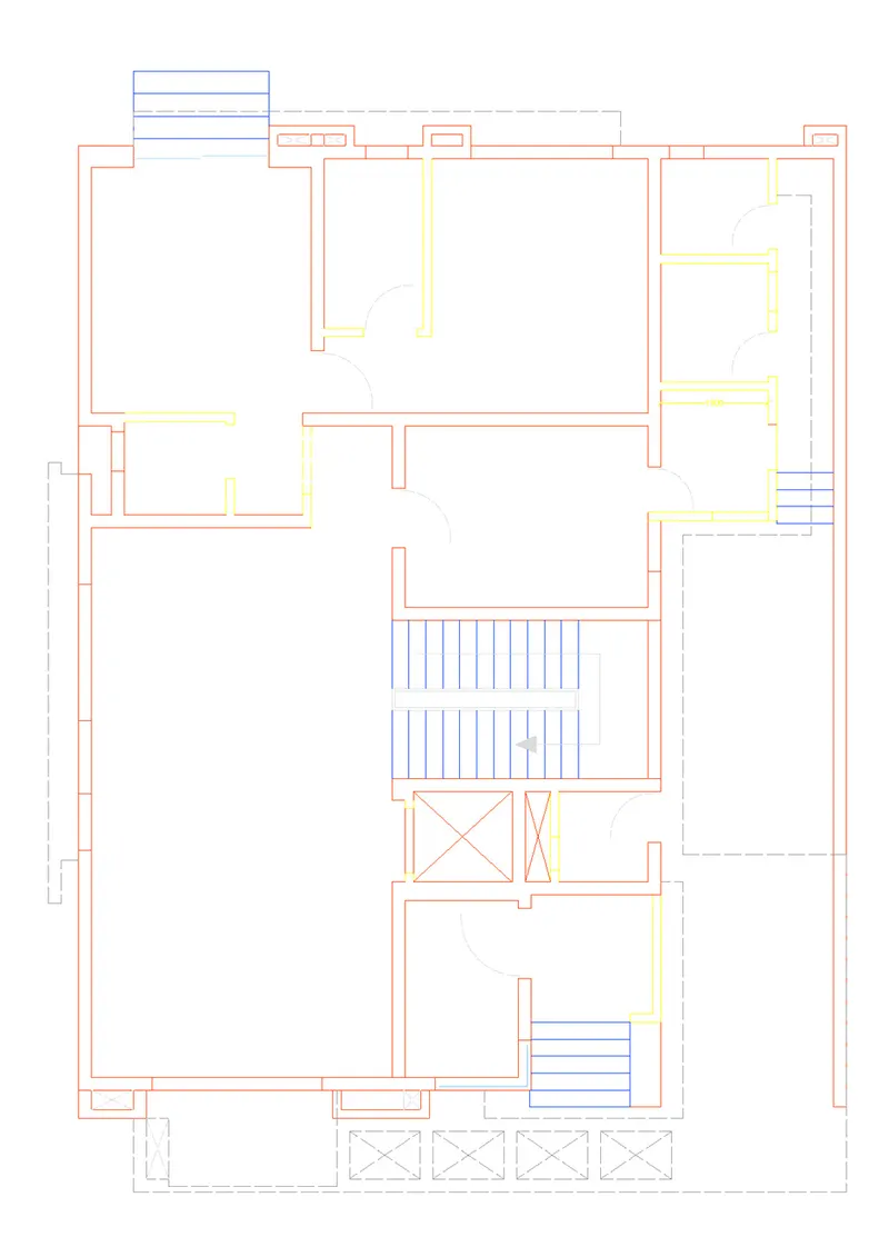
And assign the layers accordingly
Step 4
Using hatch command, dimension command and text command complete the floor plan
RESULT
3. KITCHEN LAYOUT
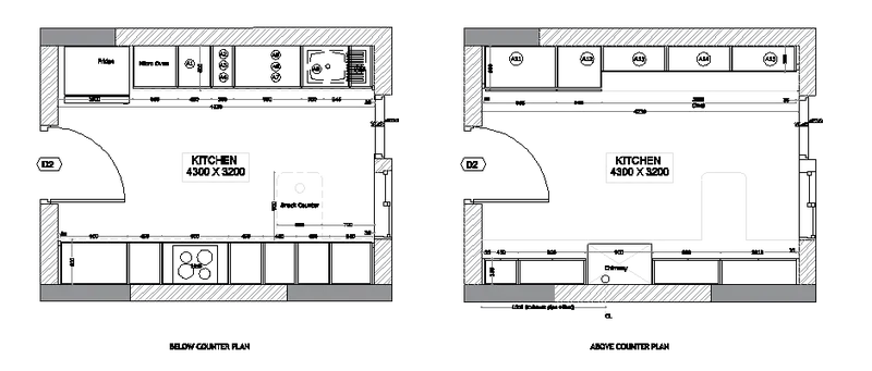
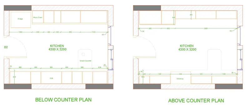
Aim: To draw the Kitchen layout as shown in the Figure above. After sketching and to provide the dimensions and text with the use of layers.
Introduction:
The Kitchen layout drawing is created in AutoCAD using the draw tools and after sketching, the dimensions and text are provided with the use of Layers. The procedure of drawing is explained and the final result is given.
Procedure:
Step 1
Type unit or UN in the command line and press enter
Set type of unit as decimal and precision as 0
In insertion scale set unit as millimeter.
Step 2
Type layer or LA in the command line and press enter
Create new layers as per requirement
Step 3
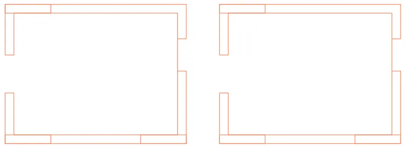
Using draw tools and offset tool draw the plan as per the given dimensions
And assign the layers accordingly
Step 4
Using hatch command, dimension command and text command complete the kitchen layout
RESULT
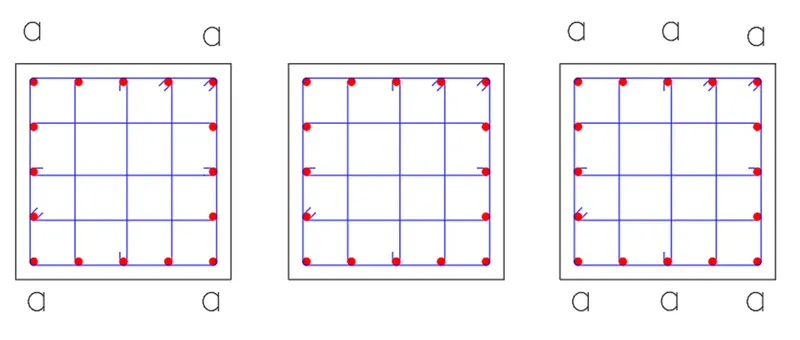
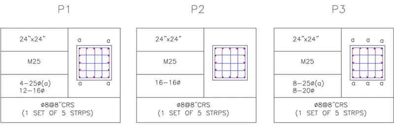
4. COLUMN SHEDULE

Aim: To create a Column Schedule as Shown in the figure above with the help of lines using AutoCAD. After sketching and to provide the dimensions and text with the use of layers.
Introduction:
The Column Schedule is created in AutoCAD using the draw tools and after sketching, the dimensions and text are provided with the use of layers. The procedure of drawing is explained and the final result is given.
Procedure:
Step 1
Type unit or UN in the command line and press enter
Set type of unit as Engineering and precision as 0’ 0”
In insertion scale set unit as inch.
Step 2
Type layer or LA in the command line and press enter
Create new layers as per requirement
Step 3
Using draw tools and offset tool draw the plan as per the given dimensions
And assign the layers accordingly
Step 4
Using dimension command and text command complete the kitchen layout
RESULT
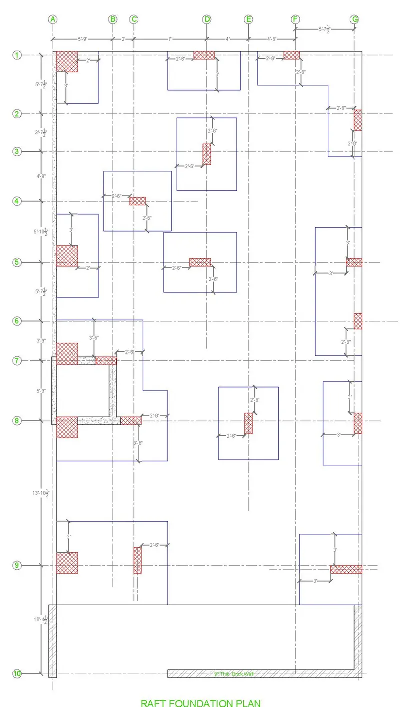
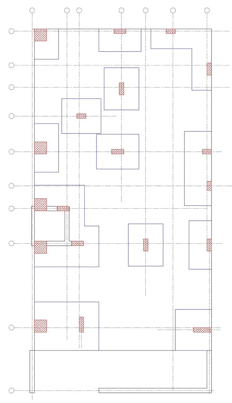
5. RAFT FOUNDATION PLAN

Aim: To draw the Raft layout as shown in the Figure above. After sketching and to provide the dimensions and text with the use of layers.
Introduction:
The Raft layout drawing is created in AutoCAD using the draw tools and after sketching, the dimensions and text are provided with the use of Layers. The procedure of drawing is explained and the final result is given.
Procedure:
Step 1
Type unit or UN in the command line and press enter
Set type of unit as Architectural and precision as 0’ 0”
In insertion scale set unit as Inches.
Step 2
Type layer or LA in the command line and press enter
Create new layers as per requirement
Step 3
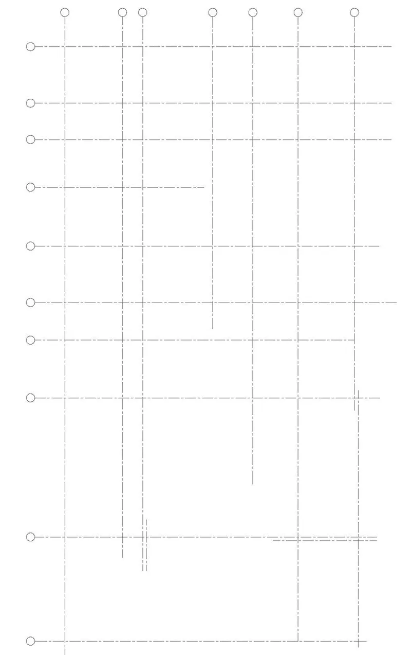
Type XL to invoke construction line
Use offset tool and draw the grids as per the given dimensions
Step 4
Using draw the column and footing as per the given dimensions
And assign the layers accordingly
Step 5
Using hatch command, dimension command and text command complete the raft foundation plan.
RESULT