Creating a Layout, Section and Elevation with dimensions using AutoCad
Creating a Plan, Section and Elevation with dimensions using AutoCAD
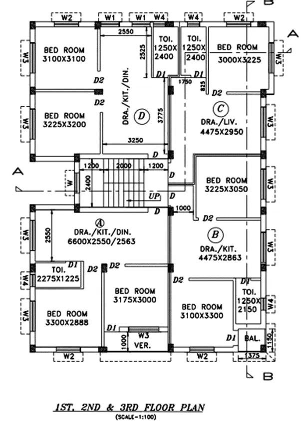
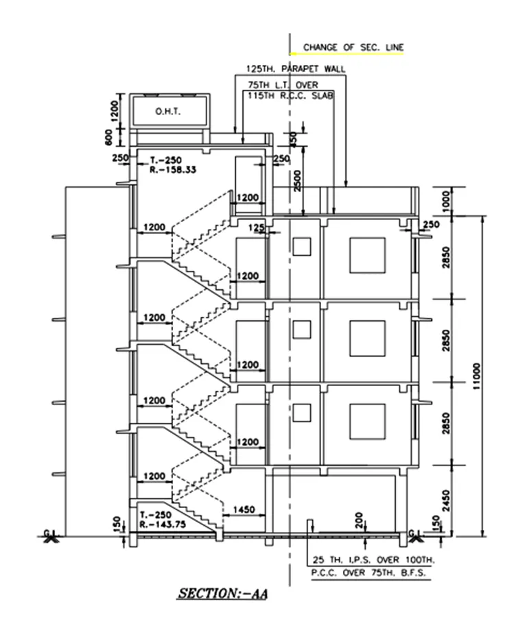
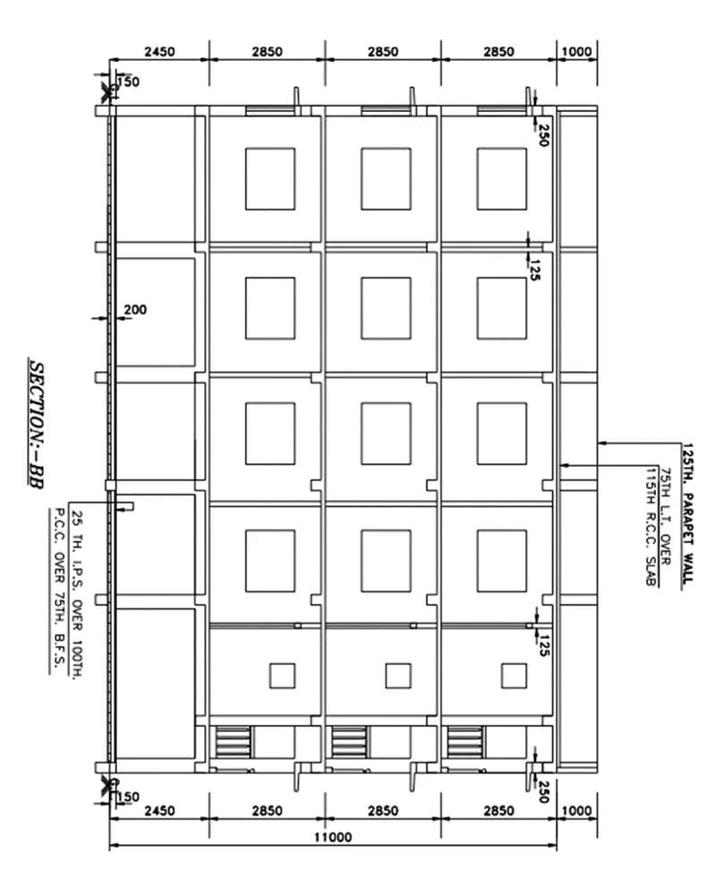
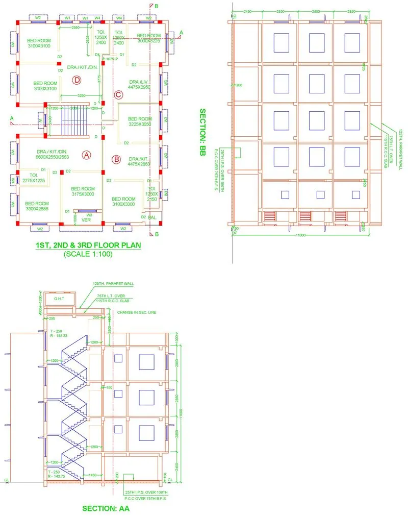
Aim: To draw the floor plan and sections in AutoCAD using the draw, modify tools with proper dimension techniques and dimension styles to the project.
Introduction:
- A plan drawing is a drawing on a horizontal plane showing a view from above.
- An Elevation drawing is drawn on a vertical plane showing a vertical depiction.
- A section drawing is also a vertical depiction but one that cuts through space showing what lies within.
- Plan and Sections are different types of drawings used by architects to graphically represent a building design and construction.
The Plan is created in AutoCAD using XLine and line tool, the dimensions and text are provided with the use of layers. The procedure of drawing is explained and the final results are given.
Commands Used:
Units
Limits
Line
Polyline
Circle
Arc
Rectangle
Trim
Extend
Offset
Mirror
Rectangular Array
Hatch
Move
Rotate
Dimlinear
Dimstyle
Fillet
Linetype
Lineweight
Layers
Mtext
Multileader
Procedure:
Step 1
Type unit or UN in the command line and press enter
Set type of unit as decimal and precision as 0
In insertion scale set unit as millimeter.
Set upper limit and lower limit of the drawing
Step 2
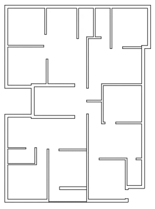
Draw the given plan using the line command, offset command as per the given dimensions.
Next, trim the unnecessary lines and objects.
Step 3
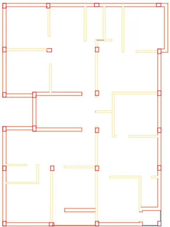
Draw columns with the size of 250mm x 350mm.
The columns are placed where ever they required in the floor plan.
Type layer or LA in the command line and press enter
Create new layers as per requirement
Assign the layers for the respective elements
And specify the column layer
Step 4
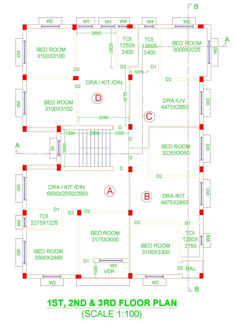
Draw doors and windows with respect the below given dimensions
|
W1 |
- 900 X 1200 mm |
|
W |
- 600 x 1200 mm |
|
W2 |
- 1000 x 1200 mm |
|
W3 |
- 1500 x 1200 mm |
|
W4 |
- 500 x 500 mm |
|
D |
- 1000 X 2100 mm |
|
D1 |
- 700 x 2100 mm |
|
D2 |
-900mm x 2100 mm |
Draw staircase with the room size of 3200mm x 2400, the tread is 250mm and riser is 143.75 in ground floor and 158.33mm thereafter.

Step 5
Indicate the rooms using the single text command.
Provide dimensions for the given floor plan using the dimlinear command.
And also draw the section lines as given in the figure, and also indicate the doors and windows.
Using hatch command, dimension command and text command complete the floor plan
Step 6
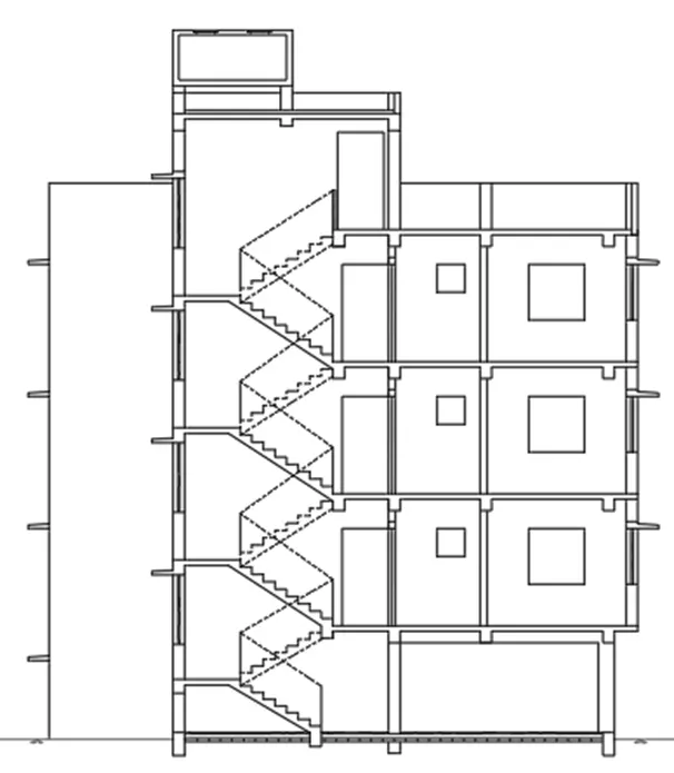
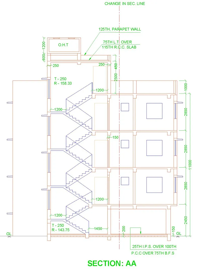
Draw the construction line from Section AA line in the plan to draw the section AA. Use copy tool to replicate construction line
The inner wall thickness is 125mm and outer wall thickness is 250mm.
And ground level thickness is 200mm and 150mm.
Next, draw the windows in them requires to places in 1st, 2nd and 3rd floors.
Using the line command, offset command and trim command draw the section AA
Draw staircase steps and landing, the tread is 250mm and riser is 143.75 in ground floor and 158.33mm thereafter.
Draw OHT and parapet wall
Step 7
Assign the layers for the respective elements
And also draw the change in section lines as given in the figure
Provide dimensions for the given Section AA using the dimlinear command.
Using hatch command, dimension command and text command complete the Section AA
Step 8
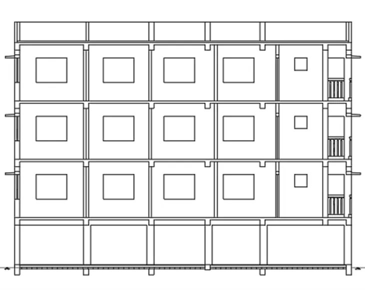
Draw the construction line from Section BB line in the plan to draw the section BB. Use copy tool to replicate construction line
The inner wall thickness is 125mm and outer wall thickness is 250mm.
And ground level thickness is 200mm and 150mm.
Next, draw the windows in them requires to places in 1st, 2nd and 3rd floors.
Using the line command, offset command and trim command draw the section AA
Step 9
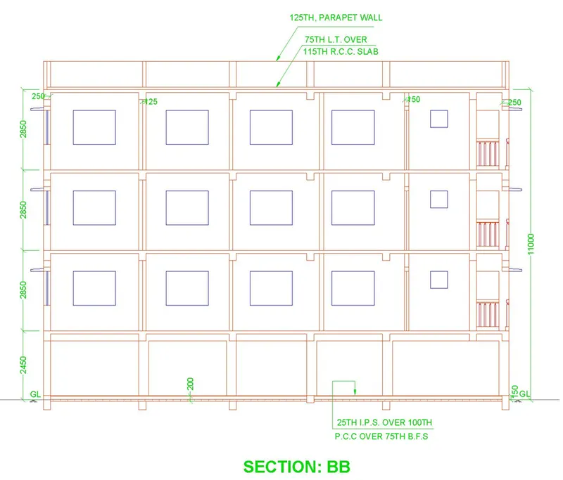
Assign the layers for the respective elements
Provide dimensions for the given Section AA using the dimlinear command.
Using hatch command, dimension command and text command complete the Section BB
RESULT