Creating 3D Isometric view of various structural elements in AutoCAD
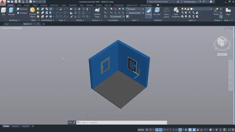
1. AIM:- To create a 3D Isometric view of the building with plan and elevation.
INTRODUCTION-:
AutoCAD-
- AutoCAD stands for Computer-Aided Design.
- AutoCAD is a software developed by the company Autodesk.
- It allows you to draw and edit digital 2D and 3D designs more quickly and easily than you could by hand.
- This software is used for designing and drafting.
- It is used for several applications like creating blueprints for buildings, bridges, etc.
- AutoCAD is a 2D and 3D computer-aided drafting software application.
- AutoCAD software saves a huge time, saving time is equal to earning more income by more output, It is simple enough software with a real user-friendly interface, It is easy to grasp and it can provide you the basic exposure, It is very beneficial in designing 3D.
- Civil engineers design, construct, supervise, operate, and maintain large construction projects and systems, including roads, buildings, airports, tunnels, dams, bridges, and systems for water supply and sewage treatment.
AutoCAD 3D- Commands
- 3DMOVE: Click 3D Move in the Modify panel on the Home tab, or type 3DMOVE at the command line.
- 3DROTATE: Click 3D Rotate in the Modify panel on the Home tab or type 3DROTATE at the command line.
- 3DSCALE: Click 3D Scale in the Modify panel, or type 3DSCALE at the command line.
- 3DALign: An improved version of the ALign command that includes additional options as well as the ability to move and rotate a copy of the selected objects and use Dynamic UCS with the command. Click 3D Align in the Modify panel on the Home tab.
- Fillet and chamfer: Because fillets and chamfers are common real-world features, it’s logical that tools for creating them are available. You can fillet or bevel the edges of a 3D solid by clicking the Fillet Edge (or Chamfer Edge) split button in the Solid Editing panel on the Solid tab.
- Shell (solid edit): Using this command you can convert a 3D solid into a hollow solid with a wall thickness. To use this command type SOLIDEDIT on the command line press enter type B press enter again type S and press enter. Alternatively, you can also select the shell tool from the Solid editing panel of the Solid tab.
- Surfpatch: Using this command you can fill the open areas of a surface like the top of a cylinder as shown in the animated image below.
- Moveface: Using this tool you can move faces like a groove of a 3D solid from one point to other as shown in the animated image below. For using this tool type SOLIDEDIT on the command line press enter then type F press enter then type M and press enter again.
- Surfoffset: Using this command you can offset any surface inside, outside, or on both sides of the surface as shown in the animated image below.
- Extrude: This AutoCAD 3D Extrude command allows the user to create a 3D object by extruding a 2D face along a line or path. For example, A cylinder can be created by selecting a 2D circle and extruding it along with a path.
- Sweep: This command helps the user to extrude the 2D objects without the 2D face being orthogonal to the beginning of the path.
- Union: This AutoCAD 3D command allows the user to combine two objects converting them into one single object.
- Subtract: This command is opposite to the union command; this command works when there is a common area in both objects. Then this command subtracts object A from object B.
- Intersect: With this AutoCAD 3D command, the user is left with the area that is common to both objects.
- Slice: The SLice command lets you cut a 3D solid along a plane. You can slice a 3D solid by using a planar curve, such as a circle, 2D polyline, or surface, among many others. When you slice a 3D solid, you can choose which part of the 3D solid is retained, or you can keep both. This image shows a solid model that has been sliced in half.
- Thicken: Using this command you can convert a surface into a 3D solid by adding thickness to it.
- Polysolid: Using this command you can make a 3D wall-like shape as shown in the image here, you can also define the height and thickness of this poly solid using command-line options.
- EDGES: You can extract edges of a 3D solid as 2D geometries using this tool. In the image shown here, the XEDGES tool has been used to extract the edges of the 3D solid and then the solid geometry has been moved to reveal the edges only.
- Flat shot: This command is great for converting a 3D drawing into 2D and using this command you can also create multiple views of a single 3D drawing like the front, top and isometric on a single plane. To know more about this command follow the related article.
- Interfere: This command can be used to detect intersecting 3D solids. The command is especially useful in situations where you want to detect clashes between different solids like pipes and walls.
- 3Dface: Defines the start point for the 3D surface. After entering the first point, enter the remaining points in a natural clockwise or counterclockwise order to create a normal 3D face. If you locate all four points on the same plane, a planar face is created that is similar to a region object.
PROCEDURE:-
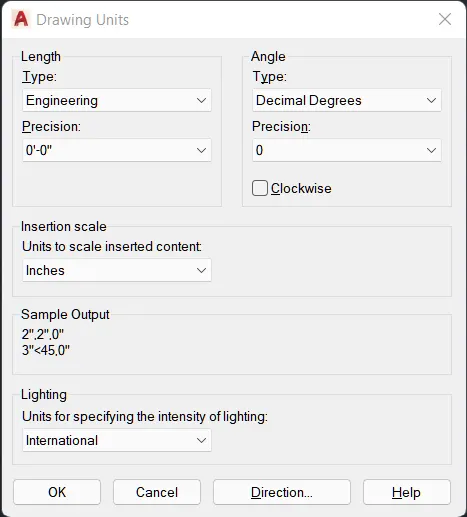
- Select un command>select engineering
- select 3D modeling workspace
- Select rec command> select dimension press enter
- select explode command
- select offset command> distance 9">select object as line>specify side press enter
- sketch window as per given dimension
- select word view
- select boundary command>select objects >press enter
- select extrude command>select object as walls>distance 10'>press enter
- select extrude command>select flooring as walls> distance 4"> press enter
- select ucs command >select face >specify face as wall>press enter
- select line command>sketch line above the flooring at the distance 3'>press enter
- select offset command>distance 4'>select window frame line>specify side >press enter
- select line command>join the window frame edges both side >press enter
- select offset command>distance 3">select object as window four frame >specify side press enter
- select offset >distance 4">select inner frame >specify side >press enter
- and sketch window handle
- select boundary command > select object >press enter
- select extrude command> select window frame surface one by one > extrude at the distance 9"> then 2 frame extrude 7">than 3 frame extrude 4">press enter+
- same as second window
- select union command> select wall as object >press enter
- select materials browser command>select mater as your requirement >select object >select material and appoint the mater>press enter
RESULT:-
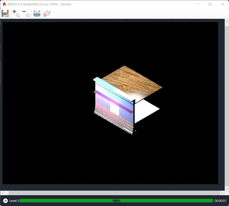
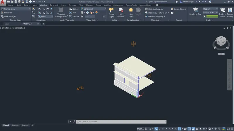
2. AIM:- TO CREATE THE 3D VIEW OF THE BUILDING FACADE AS GIVEN IN THE PLAN AND ELEVATION.
INTRODUCTION-:
AutoCAD-
- AutoCAD stands for Computer-Aided Design.
- AutoCAD is a software developed by the company Autodesk.
- It allows you to draw and edit digital 2D and 3D designs more quickly and easily than you could by hand.
- This software is used for designing and drafting.
- It is used for several applications like creating blueprints for buildings, bridges, etc.
- AutoCAD is a 2D and 3D computer-aided drafting software application.
- AutoCAD software saves a huge time, saving time is equal to earning more income by more output, It is simple enough software with a real user-friendly interface, It is easy to grasp and it can provide you the basic exposure, It is very beneficial in designing 3D.
- Civil engineers design, construct, supervise, operate, and maintain large construction projects and systems, including roads, buildings, airports, tunnels, dams, bridges, and systems for water supply and sewage treatment.
AutoCAD 3D- Commands
- 3DMOVE: Click 3D Move in the Modify panel on the Home tab, or type 3DMOVE at the command line.
- 3DROTATE: Click 3D Rotate in the Modify panel on the Home tab or type 3DROTATE at the command line.
- 3DSCALE: Click 3D Scale in the Modify panel, or type 3DSCALE at the command line.
- 3DALign: An improved version of the ALign command that includes additional options as well as the ability to move and rotate a copy of the selected objects and use Dynamic UCS with the command. Click 3D Align in the Modify panel on the Home tab.
- Fillet and chamfer: Because fillets and chamfers are common real-world features, it’s logical that tools for creating them are available. You can fillet or bevel the edges of a 3D solid by clicking the Fillet Edge (or Chamfer Edge) split button in the Solid Editing panel on the Solid tab.
- Shell (solid edit): Using this command you can convert a 3D solid into a hollow solid with a wall thickness. To use this command type SOLIDEDIT on the command line press enter type B press enter again type S and press enter. Alternatively, you can also select the shell tool from the Solid editing panel of the Solid tab.
- Surfpatch: Using this command you can fill the open areas of a surface like the top of a cylinder as shown in the animated image below.
- Moveface: Using this tool you can move faces like a groove of a 3D solid from one point to other as shown in the animated image below. For using this tool type SOLIDEDIT on the command line press enter then type F press enter then type M and press enter again.
- Surfoffset: Using this command you can offset any surface inside, outside, or on both sides of the surface as shown in the animated image below.
- Extrude: This AutoCAD 3D Extrude command allows the user to create a 3D object by extruding a 2D face along a line or path. For example, A cylinder can be created by selecting a 2D circle and extruding it along with a path.
- Sweep: This command helps the user to extrude the 2D objects without the 2D face being orthogonal to the beginning of the path.
- Union: This AutoCAD 3D command allows the user to combine two objects converting them into one single object.
- Subtract: This command is opposite to the union command; this command works when there is a common area in both objects. Then this command subtracts object A from object B.
- Intersect: With this AutoCAD 3D command, the user is left with the area that is common to both objects.
- Slice: The SLice command lets you cut a 3D solid along a plane. You can slice a 3D solid by using a planar curve, such as a circle, 2D polyline, or surface, among many others. When you slice a 3D solid, you can choose which part of the 3D solid is retained, or you can keep both. This image shows a solid model that has been sliced in half.
- Thicken: Using this command you can convert a surface into a 3D solid by adding thickness to it.
- Polysolid: Using this command you can make a 3D wall-like shape as shown in the image here, you can also define the height and thickness of this poly solid using command-line options.
- EDGES: You can extract edges of a 3D solid as 2D geometries using this tool. In the image shown here, the XEDGES tool has been used to extract the edges of the 3D solid and then the solid geometry has been moved to reveal the edges only.
- Flat shot: This command is great for converting a 3D drawing into 2D and using this command you can also create multiple views of a single 3D drawing like the front, top and isometric on a single plane. To know more about this command follow the related article.
- Interfere: This command can be used to detect intersecting 3D solids. The command is especially useful in situations where you want to detect clashes between different solids like pipes and walls.
- 3Dface: Defines the start point for the 3D surface. After entering the first point, enter the remaining points in a natural clockwise or counterclockwise order to create a normal 3D face. If you locate all four points on the same plane, a planar face is created that is similar to a region object.
PROCEDURE:-
- Select un command>select engineering
- select 3D modeling workspace
-
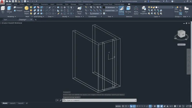
- SELECT line command> specify first point>drag the cursor -ve y-axis>distance 10'9">continue drag the cursor x-axis>distance 6'9">continue drag cursor y-axis>distance 10'9">press entre
- select offset command>distance 9">select all walls one by one >specify side >press enter
- sketch window as per give dimension
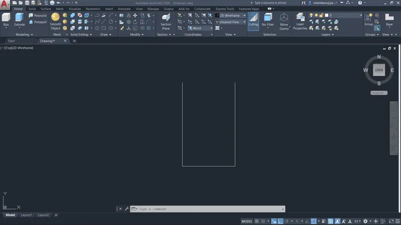
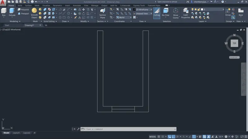
- select word view option
- select boundary command>select wall as object >extrude distance 12'9"
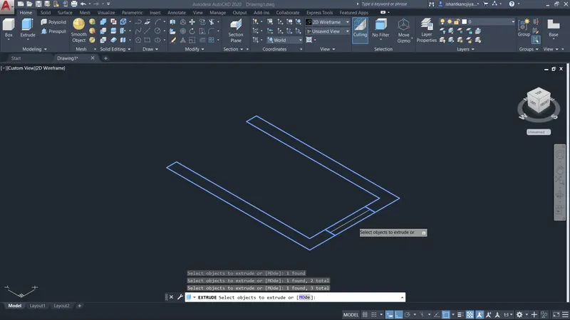
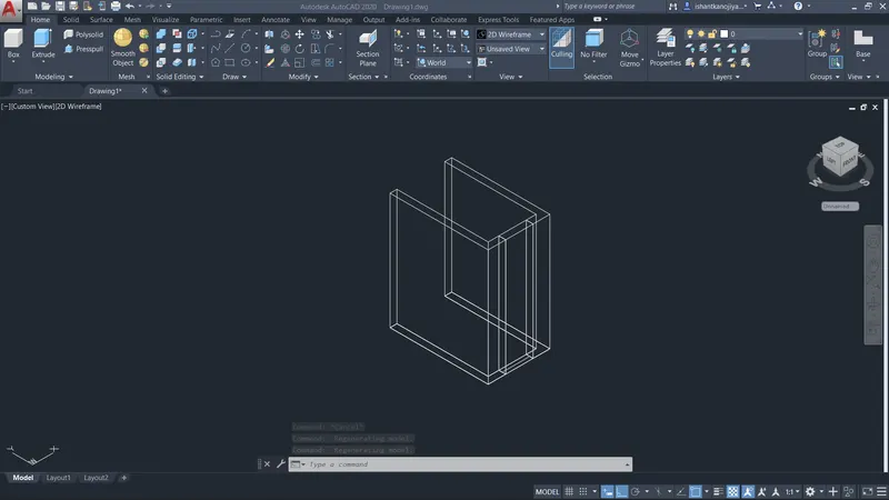
- select ucs >select face>select wall as object (face)>press enter
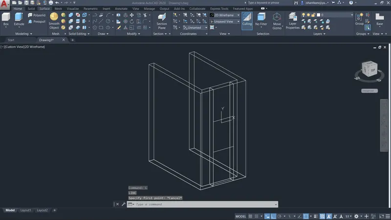
- select line command>sketch the frame of window plan>select line and move above the flooring at the distance 4'6">press enter
- select offset command>distance 4'>select last line as object >specify side > press enter
- select line command>join the last two lines edge to edge bothside>press enter
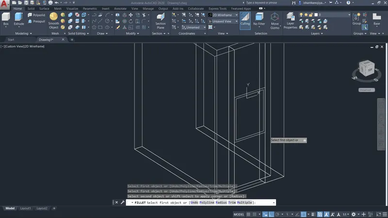
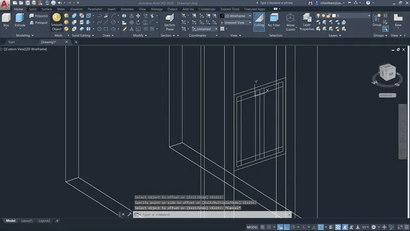
- select offset command>distance 2">select window frame >specify inner side>press enter
- select offset command>distance 3">select last frame>specify side press enter
- select fillet command>select object >press enter
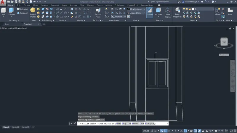
- select boundary command>select window frame as object>press enter
- select extrude command>select window frame surface>extrude at a distance 9">press enter
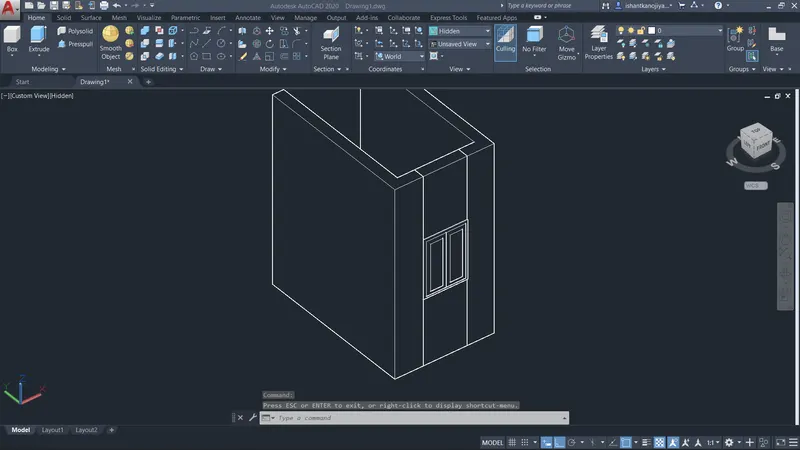
- select union command>select wall as object >press enter
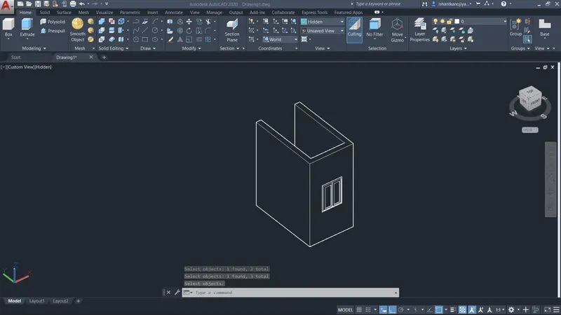
- select copy command>select all things as object >select pick point >specify location to copy>press enter
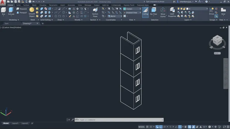
- sketch rest objects
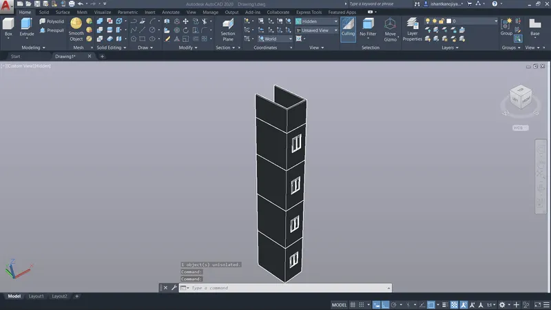
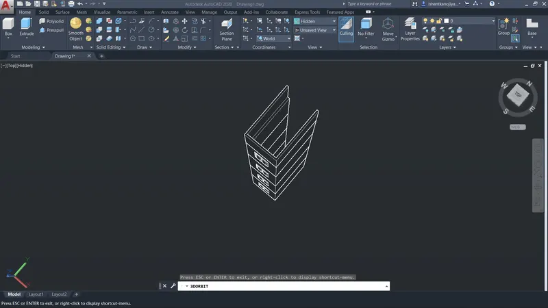
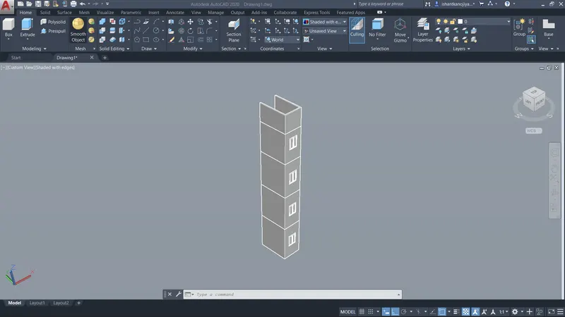
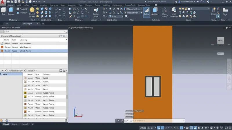
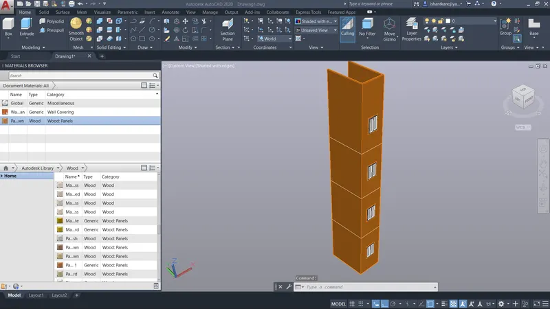
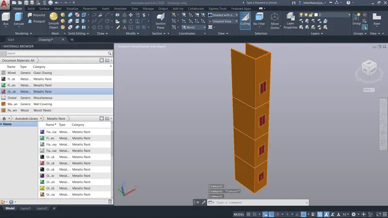
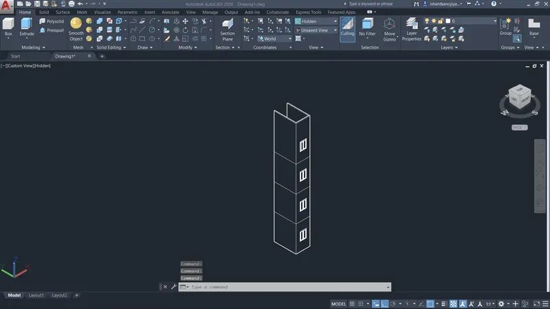
- select materials browsing command>select required mater>select object >select material >appoint the material
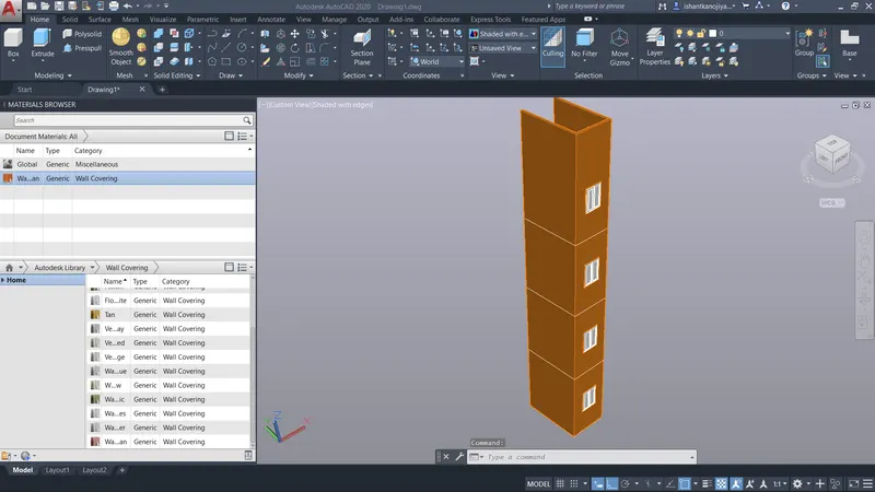
RESULT:-
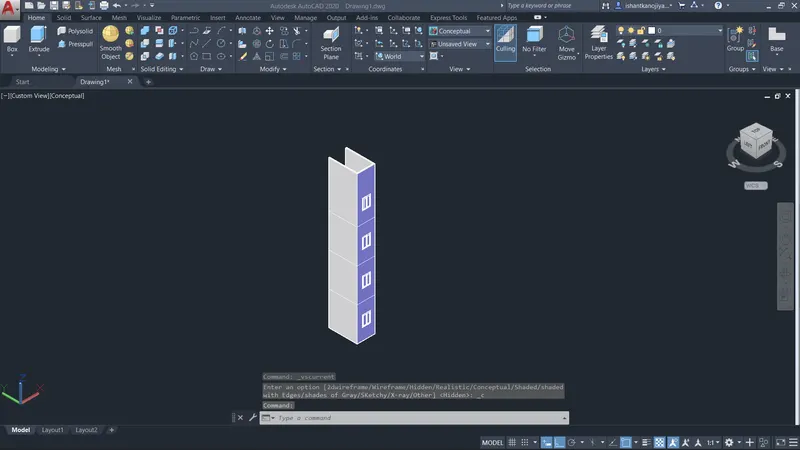
3. AIM:- TO CREATE THE ISOMETRIC 3D VIEW OF STAIRS WITH RAILING AS SHOWN IN THE PLAN AND ELEVATION.
INTRODUCTION-:
AutoCAD-
- AutoCAD stands for Computer-Aided Design.
- AutoCAD is a software developed by the company Autodesk.
- It allows you to draw and edit digital 2D and 3D designs more quickly and easily than you could by hand.
- This software is used for designing and drafting.
- It is used for several applications like creating blueprints for buildings, bridges, etc.
- AutoCAD is a 2D and 3D computer-aided drafting software application.
- AutoCAD software saves a huge time, saving time is equal to earning more income by more output, It is simple enough software with a real user-friendly interface, It is easy to grasp and it can provide you the basic exposure, It is very beneficial in designing 3D.
- Civil engineers design, construct, supervise, operate, and maintain large construction projects and systems, including roads, buildings, airports, tunnels, dams, bridges, and systems for water supply and sewage treatment.
AutoCAD 3D- Commands
- 3DMOVE: Click 3D Move in the Modify panel on the Home tab, or type 3DMOVE at the command line.
- 3DROTATE: Click 3D Rotate in the Modify panel on the Home tab or type 3DROTATE at the command line.
- 3DSCALE: Click 3D Scale in the Modify panel, or type 3DSCALE at the command line.
- 3DALign: An improved version of the ALign command that includes additional options as well as the ability to move and rotate a copy of the selected objects and use Dynamic UCS with the command. Click 3D Align in the Modify panel on the Home tab.
- Fillet and chamfer: Because fillets and chamfers are common real-world features, it’s logical that tools for creating them are available. You can fillet or bevel the edges of a 3D solid by clicking the Fillet Edge (or Chamfer Edge) split button in the Solid Editing panel on the Solid tab.
- Shell (solid edit): Using this command you can convert a 3D solid into a hollow solid with a wall thickness. To use this command type SOLIDEDIT on the command line press enter type B press enter again type S and press enter. Alternatively, you can also select the shell tool from the Solid editing panel of the Solid tab.
- Surfpatch: Using this command you can fill the open areas of a surface like the top of a cylinder as shown in the animated image below.
- Moveface: Using this tool you can move faces like a groove of a 3D solid from one point to other as shown in the animated image below. For using this tool type SOLIDEDIT on the command line press enter then type F press enter then type M and press enter again.
- Surfoffset: Using this command you can offset any surface inside, outside, or on both sides of the surface as shown in the animated image below.
- Extrude: This AutoCAD 3D Extrude command allows the user to create a 3D object by extruding a 2D face along a line or path. For example, A cylinder can be created by selecting a 2D circle and extruding it along with a path.
- Sweep: This command helps the user to extrude the 2D objects without the 2D face being orthogonal to the beginning of the path.
- Union: This AutoCAD 3D command allows the user to combine two objects converting them into one single object.
- Subtract: This command is opposite to the union command; this command works when there is a common area in both objects. Then this command subtracts object A from object B.
- Intersect: With this AutoCAD 3D command, the user is left with the area that is common to both objects.
- Slice: The SLice command lets you cut a 3D solid along a plane. You can slice a 3D solid by using a planar curve, such as a circle, 2D polyline, or surface, among many others. When you slice a 3D solid, you can choose which part of the 3D solid is retained, or you can keep both. This image shows a solid model that has been sliced in half.
- Thicken: Using this command you can convert a surface into a 3D solid by adding thickness to it.
- Polysolid: Using this command you can make a 3D wall-like shape as shown in the image here, you can also define the height and thickness of this poly solid using command-line options.
- EDGES: You can extract edges of a 3D solid as 2D geometries using this tool. In the image shown here, the XEDGES tool has been used to extract the edges of the 3D solid and then the solid geometry has been moved to reveal the edges only.
- Flat shot: This command is great for converting a 3D drawing into 2D and using this command you can also create multiple views of a single 3D drawing like the front, top and isometric on a single plane. To know more about this command follow the related article.
- Interfere: This command can be used to detect intersecting 3D solids. The command is especially useful in situations where you want to detect clashes between different solids like pipes and walls.
- 3Dface: Defines the start point for the 3D surface. After entering the first point, enter the remaining points in a natural clockwise or counterclockwise order to create a normal 3D face. If you locate all four points on the same plane, a planar face is created that is similar to a region object.
PROCEDURE:-
- Select un command>select engineering
- select 3D modeling workspace
-
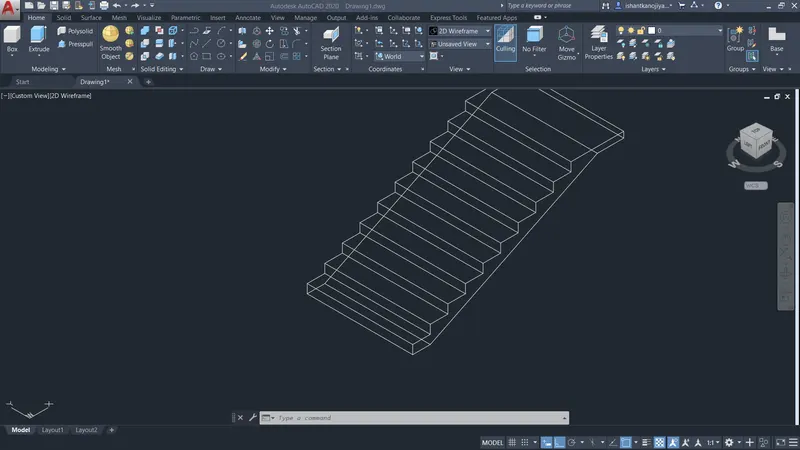
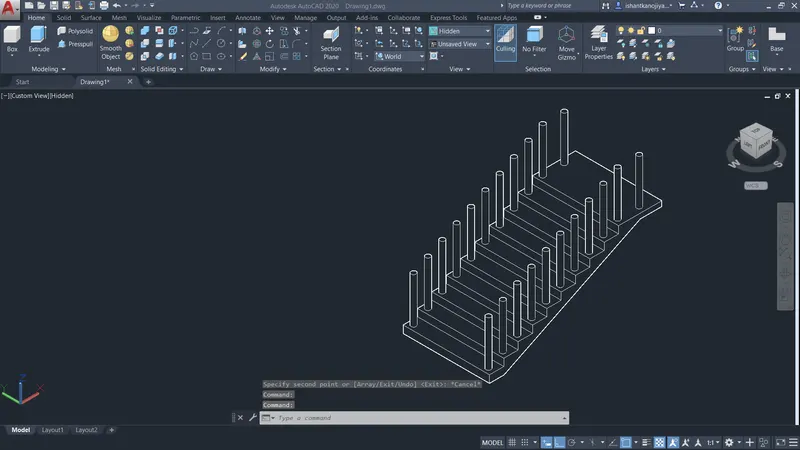
- select line command>specify the first point>sketch raiser 6">sketch trade 1'>repate 9 times>than sketch lander 3'>press enter
- select 3dr command>select side elevation as object >rotate about x-axis>at the angle 90 degree>press enter
- select joint command>select all object >press enter
- select extrude command>select stair as object >extrude distance 1'>press enter
- select ucs command>select face>specify face as first trade face >press enter
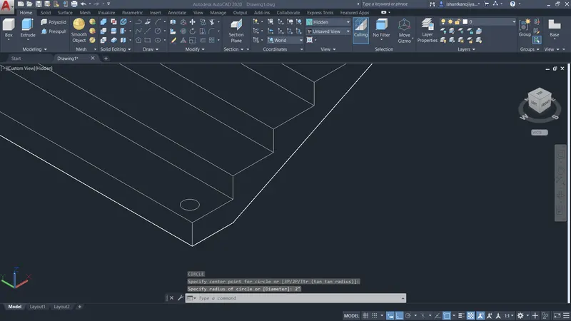
- select circle command>specify center> radius 2">press enter
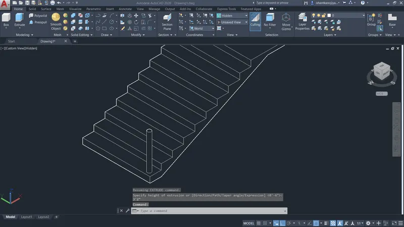
- select extrude command>select circle as object >extrude distance 3'2">press enter
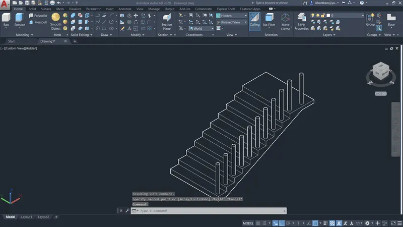
- select copy command>select railing as object >select pick point as edge of trade>copy the object avery trade one by one
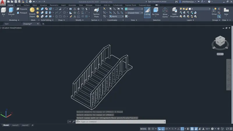
- select sweep command>select object as circle>select path >press enter
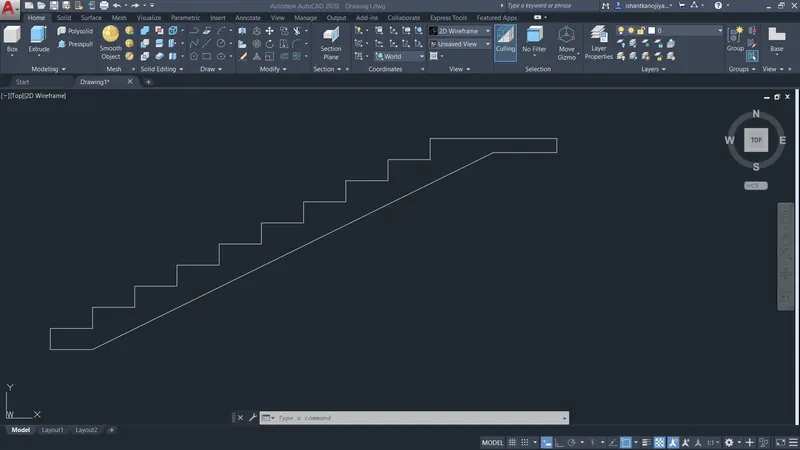
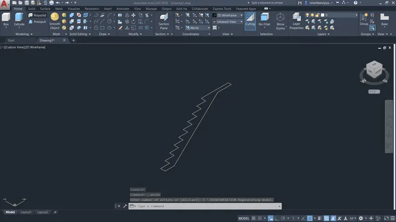
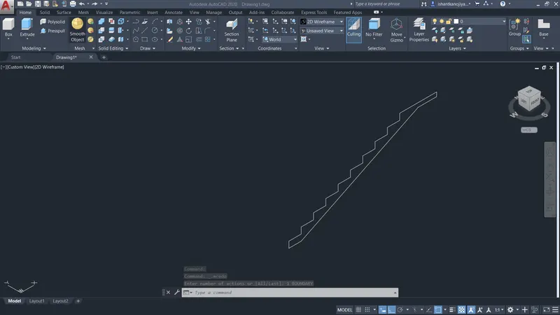
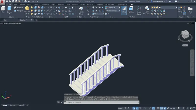
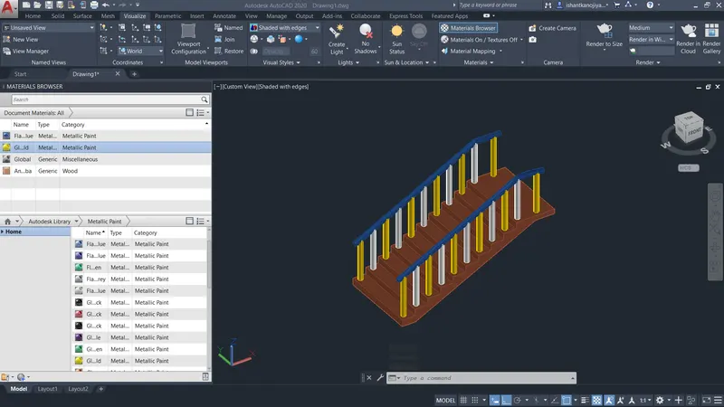
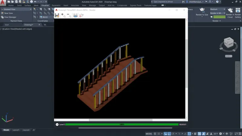
- select material browser command>select material required >select object >appoint the material
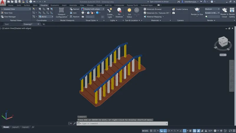
RESULT-:
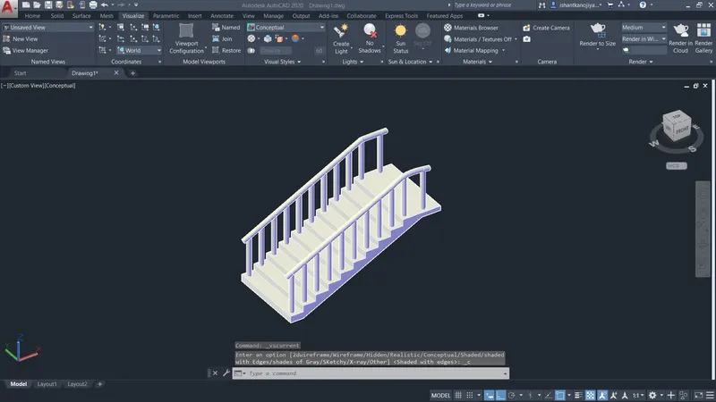
4. AIM:- TO CREATE THE 3D VIEW OF A WALL WITH SPREAD FOOTING
INTRODUCTION-:
AutoCAD-
- AutoCAD stands for Computer-Aided Design.
- AutoCAD is a software developed by the company Autodesk.
- It allows you to draw and edit digital 2D and 3D designs more quickly and easily than you could by hand.
- This software is used for designing and drafting.
- It is used for several applications like creating blueprints for buildings, bridges, etc.
- AutoCAD is a 2D and 3D computer-aided drafting software application.
- AutoCAD software saves a huge time, saving time is equal to earning more income by more output, It is simple enough software with a real user-friendly interface, It is easy to grasp and it can provide you the basic exposure, It is very beneficial in designing 3D.
- Civil engineers design, construct, supervise, operate, and maintain large construction projects and systems, including roads, buildings, airports, tunnels, dams, bridges, and systems for water supply and sewage treatment.
AutoCAD 3D- Commands
- 3DMOVE: Click 3D Move in the Modify panel on the Home tab, or type 3DMOVE at the command line.
- 3DROTATE: Click 3D Rotate in the Modify panel on the Home tab or type 3DROTATE at the command line.
- 3DSCALE: Click 3D Scale in the Modify panel, or type 3DSCALE at the command line.
- 3DALign: An improved version of the ALign command that includes additional options as well as the ability to move and rotate a copy of the selected objects and use Dynamic UCS with the command. Click 3D Align in the Modify panel on the Home tab.
- Fillet and chamfer: Because fillets and chamfers are common real-world features, it’s logical that tools for creating them are available. You can fillet or bevel the edges of a 3D solid by clicking the Fillet Edge (or Chamfer Edge) split button in the Solid Editing panel on the Solid tab.
- Shell (solid edit): Using this command you can convert a 3D solid into a hollow solid with a wall thickness. To use this command type SOLIDEDIT on the command line press enter type B press enter again type S and press enter. Alternatively, you can also select the shell tool from the Solid editing panel of the Solid tab.
- Surfpatch: Using this command you can fill the open areas of a surface like the top of a cylinder as shown in the animated image below.
- Moveface: Using this tool you can move faces like a groove of a 3D solid from one point to other as shown in the animated image below. For using this tool type SOLIDEDIT on the command line press enter then type F press enter then type M and press enter again.
- Surfoffset: Using this command you can offset any surface inside, outside, or on both sides of the surface as shown in the animated image below.
- Extrude: This AutoCAD 3D Extrude command allows the user to create a 3D object by extruding a 2D face along a line or path. For example, A cylinder can be created by selecting a 2D circle and extruding it along with a path.
- Sweep: This command helps the user to extrude the 2D objects without the 2D face being orthogonal to the beginning of the path.
- Union: This AutoCAD 3D command allows the user to combine two objects converting them into one single object.
- Subtract: This command is opposite to the union command; this command works when there is a common area in both objects. Then this command subtracts object A from object B.
- Intersect: With this AutoCAD 3D command, the user is left with the area that is common to both objects.
- Slice: The SLice command lets you cut a 3D solid along a plane. You can slice a 3D solid by using a planar curve, such as a circle, 2D polyline, or surface, among many others. When you slice a 3D solid, you can choose which part of the 3D solid is retained, or you can keep both. This image shows a solid model that has been sliced in half.
- Thicken: Using this command you can convert a surface into a 3D solid by adding thickness to it.
- Polysolid: Using this command you can make a 3D wall-like shape as shown in the image here, you can also define the height and thickness of this poly solid using command-line options.
- EDGES: You can extract edges of a 3D solid as 2D geometries using this tool. In the image shown here, the XEDGES tool has been used to extract the edges of the 3D solid and then the solid geometry has been moved to reveal the edges only.
- Flat shot: This command is great for converting a 3D drawing into 2D and using this command you can also create multiple views of a single 3D drawing like the front, top and isometric on a single plane. To know more about this command follow the related article.
- Interfere: This command can be used to detect intersecting 3D solids. The command is especially useful in situations where you want to detect clashes between different solids like pipes and walls.
- 3Dface: Defines the start point for the 3D surface. After entering the first point, enter the remaining points in a natural clockwise or counterclockwise order to create a normal 3D face. If you locate all four points on the same plane, a planar face is created that is similar to a region object.
PROCEDURE:-
- Select un command>select decimal>select scale mm>select precision 0.0>press enter
- select 3D modeling workspace
- select pdf import >select pdf to impote>select page >press ok
- select scale >select reference >specify reference >press enter
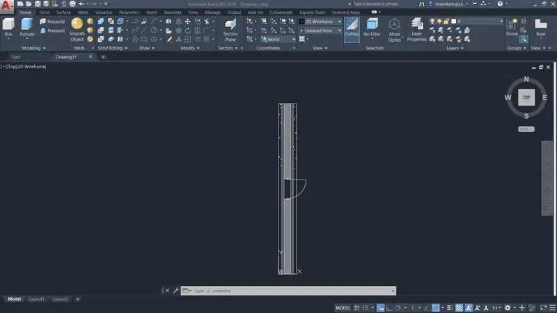
- select bo command>select inner side >press enter(boundary is created)
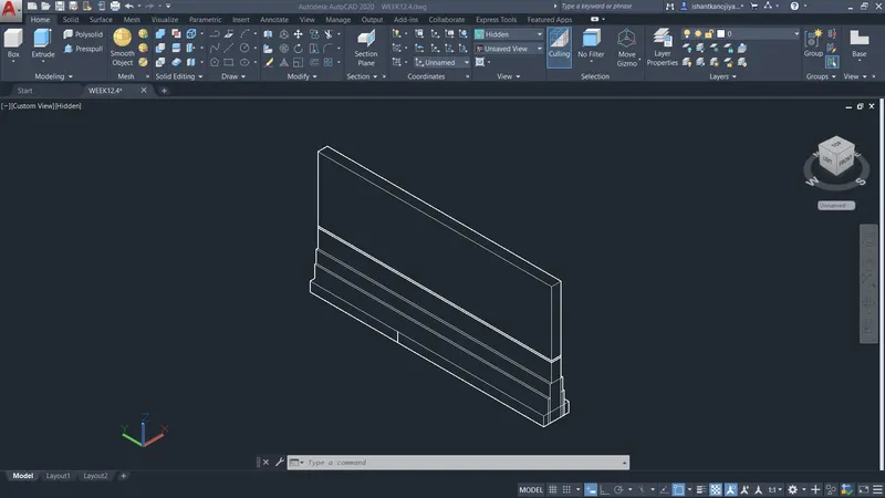
- select extrude command>select foundation>distance 300>press enter
- select extrude command>select wall >extrude distance 700
- select extrude >select wall>extude 1100
- select wall>extrude wall>extrude 1700
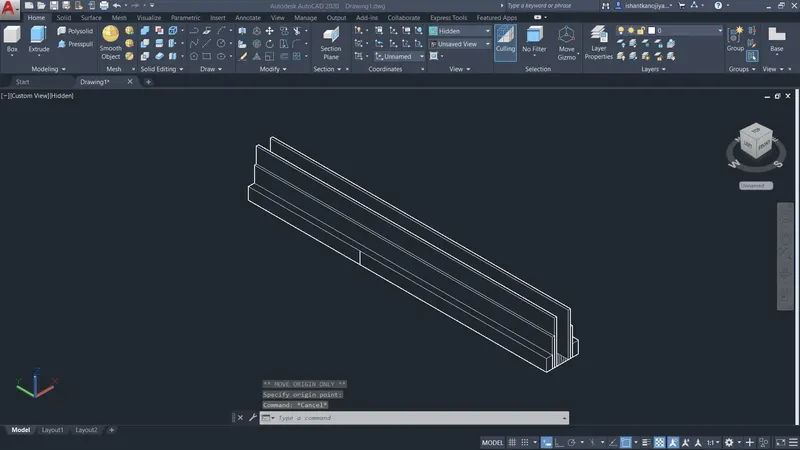
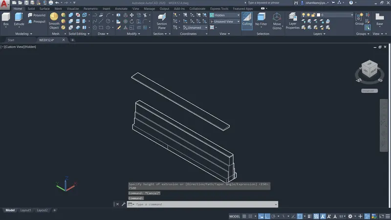
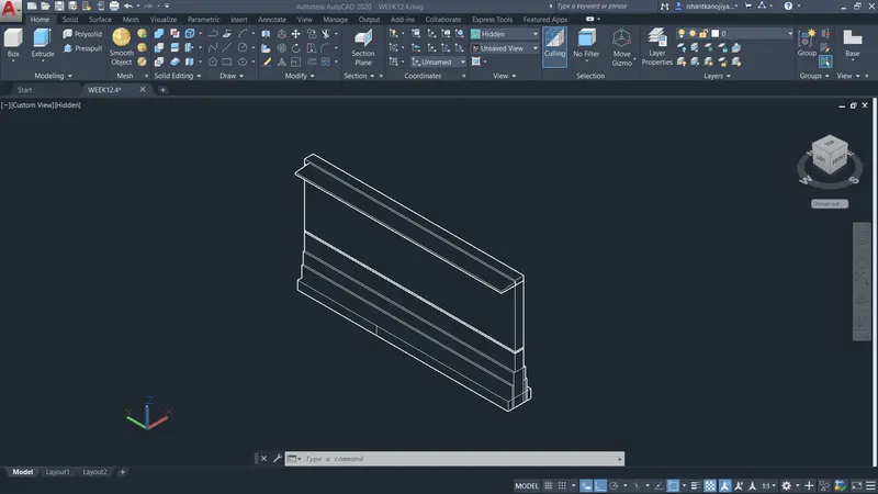
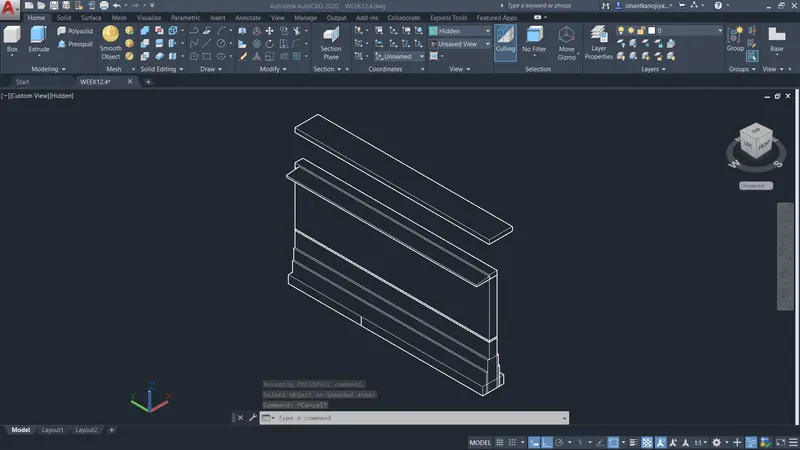
- using press pull command or subtract command
- using isolate>hide press enter
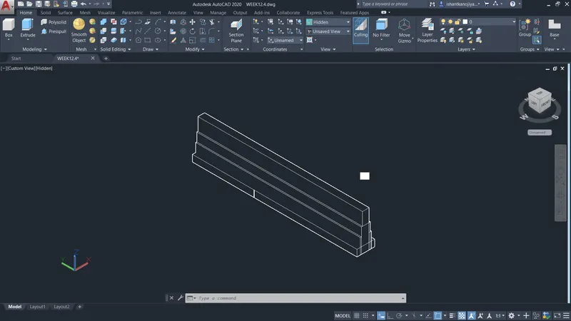
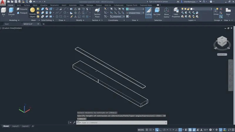
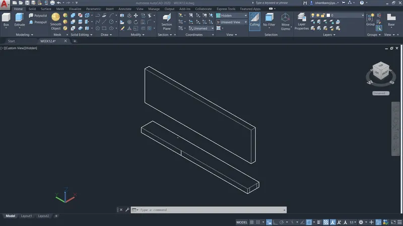
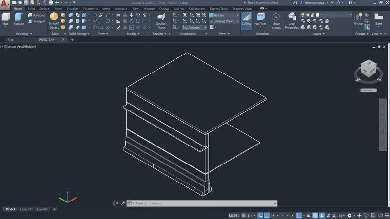
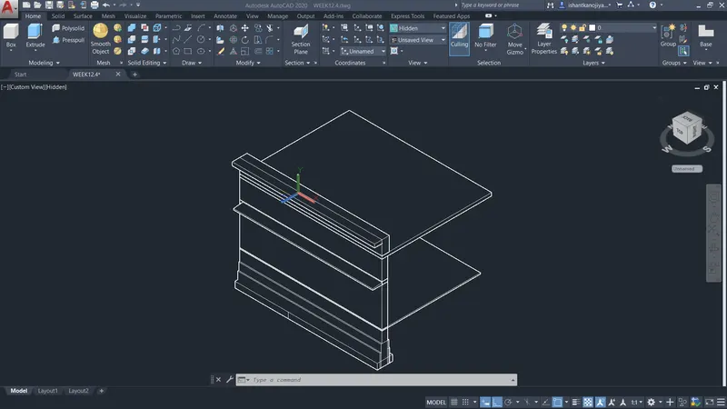
- cut the door
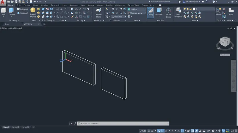
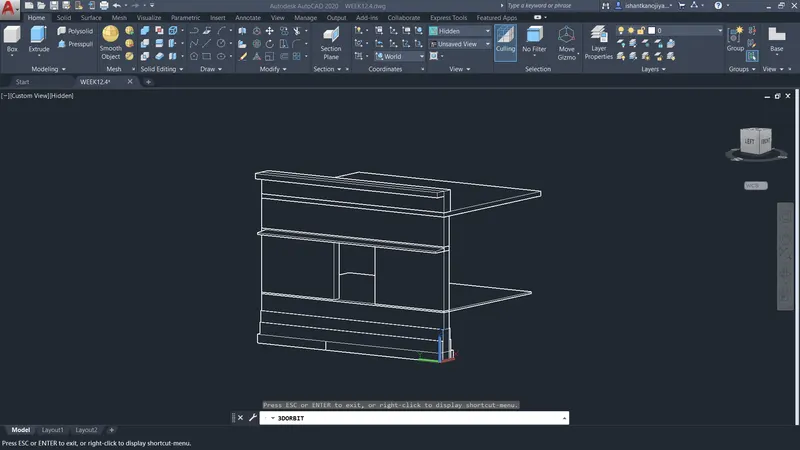
- select materials browsering >select material>select object >point the material
- select rr command >press enter(render the image)
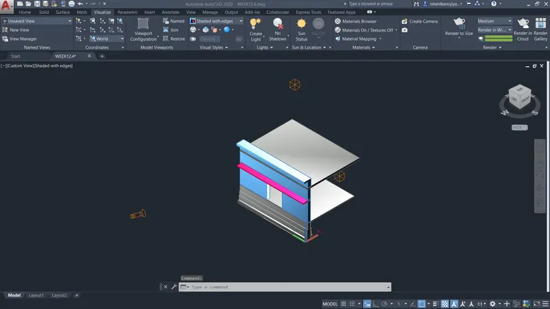
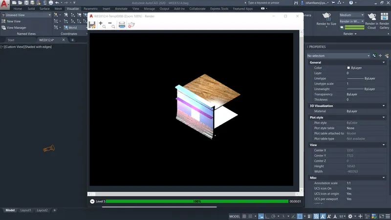
RESULT-: