Creating 3D Isometric view of various structural elements in AutoCAD
Aim & Introduction: To create a 3D Isometric View of the building with given plan and elevation.
Commands used:
- Rectangle
- Line
- Explode
- Extend
- View
- 3D orbit
- Boundary
- Extrude
- Union
- Subtract
- Align
Procedure:
- Open new drawing file
- Change the setting in to 3d modelling
- Change unit to engineering
- Change the dimension settings (D > Modify > primary units > engineering > set to current)
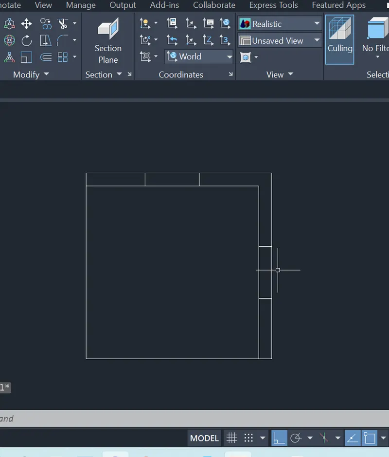
Creating plan
- Rectangle > specify point >10’-9”,10’-9” > enter
- Offset > 9“>select the last rectangle > select inner side of the rectangle
- Explode > select the last rectangle > enter
- Delete > select two lines of last exploded rectangle >enter
- Extend > boundary >select the outer rectangle > select the corner of line at extended direction
- Offset > 4’-3” > select the vertical line of outer rectangle > select direction
- Offset > 3’ > select last line> select direction
- Offset > 4’-2” > select the horizontal line of outer rectangle > select direction
- Offset > 3’-2” > select last line> select
- Trim > select object: Select lines which is not required to remove
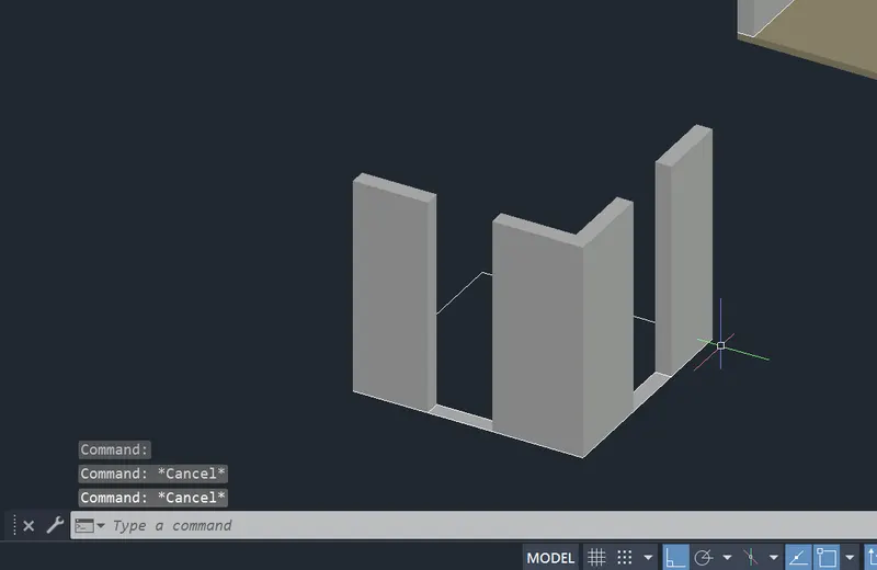
- Change the view to SW- Isometric
- Boundary > select objects > enter
- Extrude >select the wall region > 10’
- Extrude >select the window region > 3’
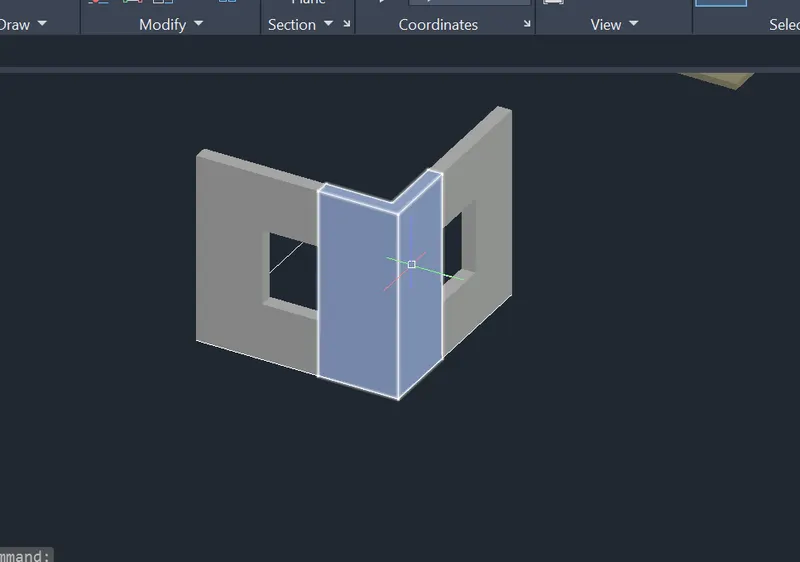
- UCS > Face > select top of solid > pace point
- Create the rectangle open area at top of both opening window
- Extrude > select the both rectangle region > -3
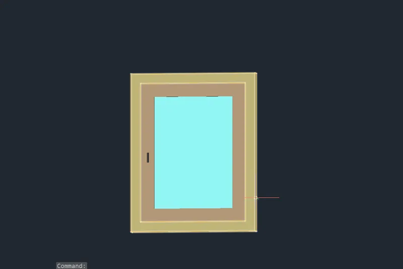
Creating windows:
- Rectangle > specify point > 3’,4’> enter
- Offset > 3” > select last rectangle > select inner direction.
- Offset > 4” > select last offset rectangle > select inner direction.
- Region > select all rectangle >Enter.
- Subtract > select the first rectangle > select the second rectangle
- Do the above step for mullion and glass.
- Layer > 3d frame > set to current layer
- Extrude the frame up to 3”
- Layer > 3d mullion > set to current layer
- Extrude the mullion up to 2”
- Layer > 3d glass > set to current layer
- Extrude the glass up to 0.5”
- Move the windows up to 1” from wall
- change colour in properties of selected solids
Creating surface and roof:
- UCS > face > select the face
- Create a rectangle at surface of 4”
- Rectangle > specify the corner of the wall > 10’-9”, 4”.
- Rectangle > specify the corner of top wall > 10’-9”, 6”.
- Extrude both the rectangles up to 10’-9”
- Extrude > select the rectangle region> specify direction> 10’-9”.
- change colour in properties of selected solids
3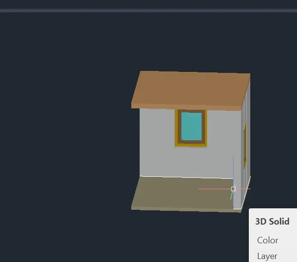
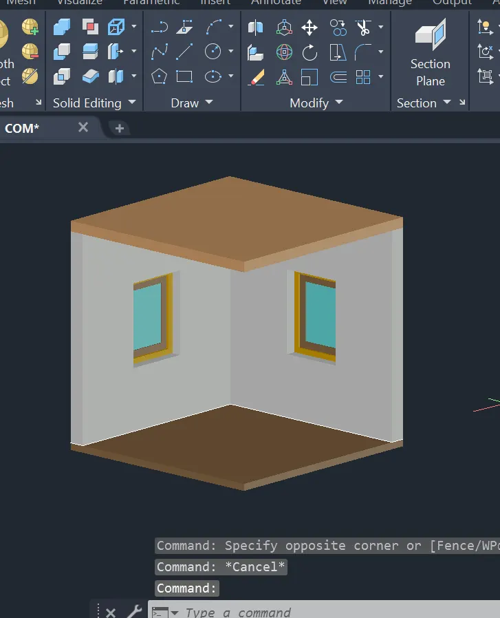
Result:
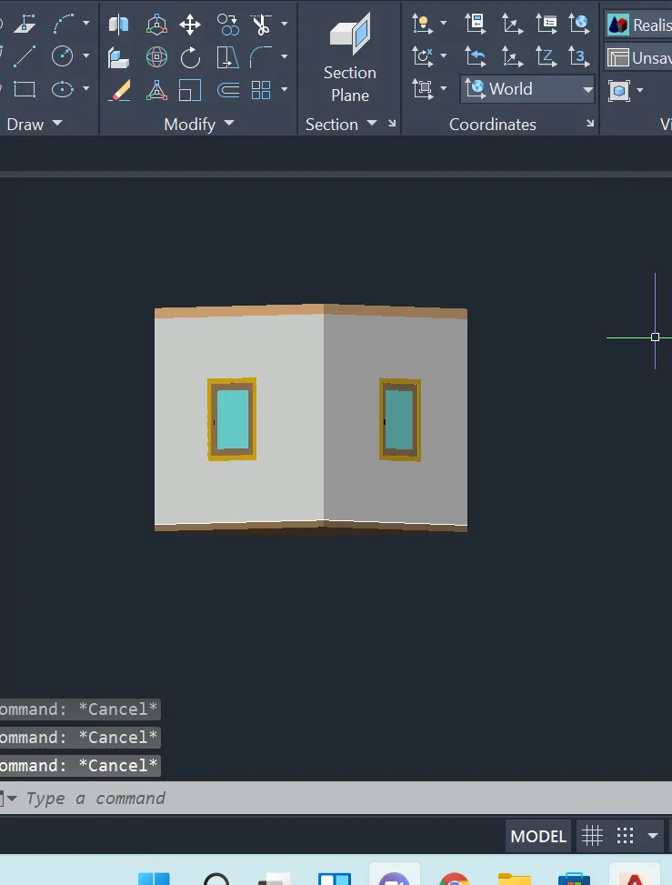
- The view mode is in realistic at custom view angle
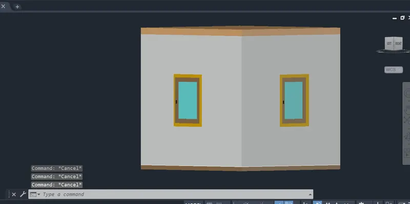
Aim & Introduction: To create the 3D View of the Building Façade as given in the plan and elevation by using autocad software. the details are provided below.
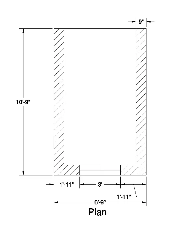
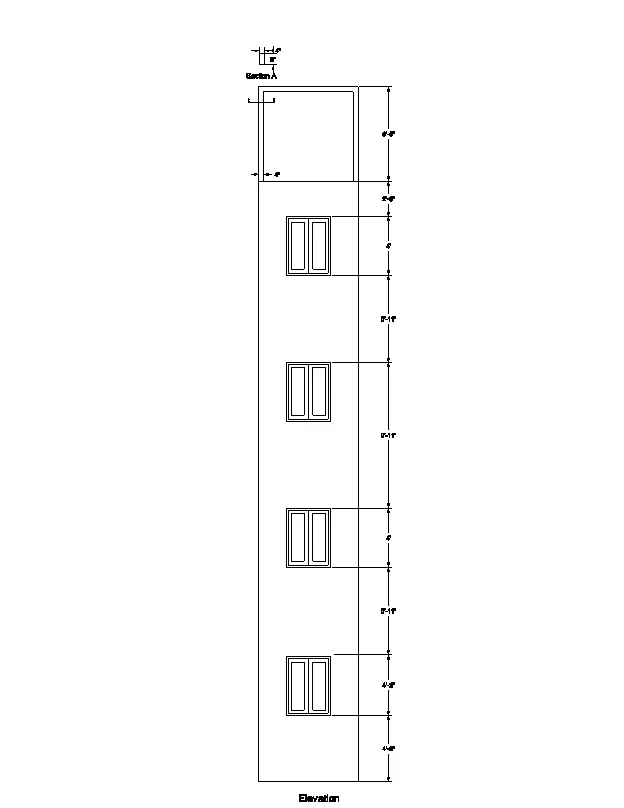
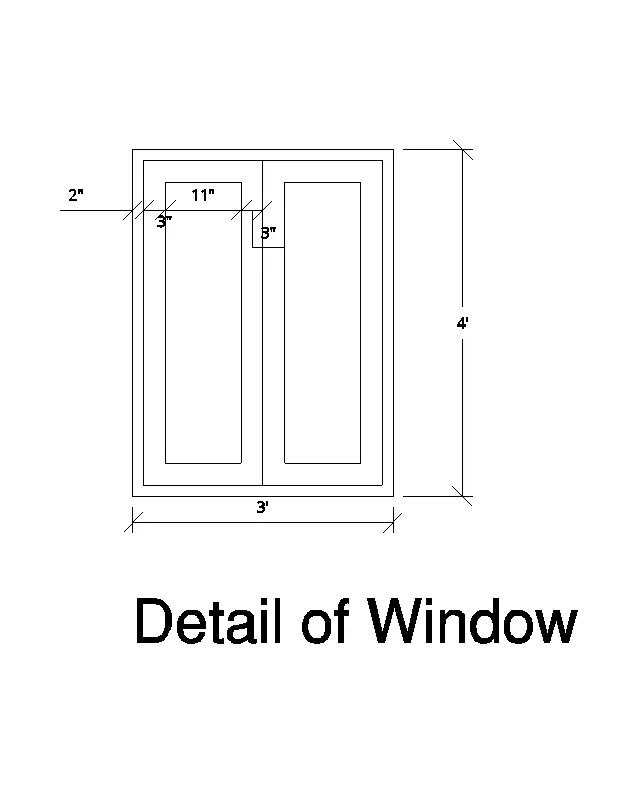
Commands used:
- Rectangle
- Line
- Explode
- Extend
- View
- 3D orbit
- Boundary
- Extrude
- Union
- Subtract
- Align
Procedure:
- Open new drawing file
- Change the setting in to 3d modelling
- Change unit to engineering
- Change the dimension settings (D > Modify > primary units > engineering > set to current)
Creating plan
- Rectangle > specify point >10’-9”,6'9” > enter
- Offset > 9“>select the last rectangle > select inner side of the rectangle
- Explode > select the last rectangle > enter
- Delete > select two lines of last exploded rectangle >enter
- Extend > boundary >select the outer rectangle > select the corner of line at extended direction
- Offset > 1’-1” > select the line of outer rectangle > select direction
- Offset > 3’ > select last line> select direction
- Trim > select object: Select lines which is not required to remove
Creating the elevation :
- Line >specify point > 6’-9”
- XL> vertical > provide both corners of lines
- Offset >4’6”>select the last line >specify direction upwards
- Offset >4’2”>select the last line >specify direction upwards
- Offset >5’11”>select the last line >specify direction upwards
- Offset >4’select the last line >specify direction upwards
- Offset >9’-11”>select the last line >specify direction upwards
- Offset >5’-11”>select the last line >specify direction upwards
- Offset >4’ > select the last line >specify direction upwards
- Offset >2’5”>select the last line >specify direction upwards
- Offset >6’-5”>select the last line >specify direction upwards
- Offset >1’-11”>select the vertical line >specify direction right
- Offset >1’-11”>select the vertical line >specify direction to left side
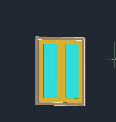
Creating windows:
- Rectangle > specify point > 3’,4’> enter
- Offset > 2” > select last rectangle > select inner direction.
- Offset > 3” > select last offset rectangle > select inner direction.
- Region > select all rectangle >Enter.
- Subtract > select the first rectangle > select the second rectangle
- Do the above step for mullion and glass.
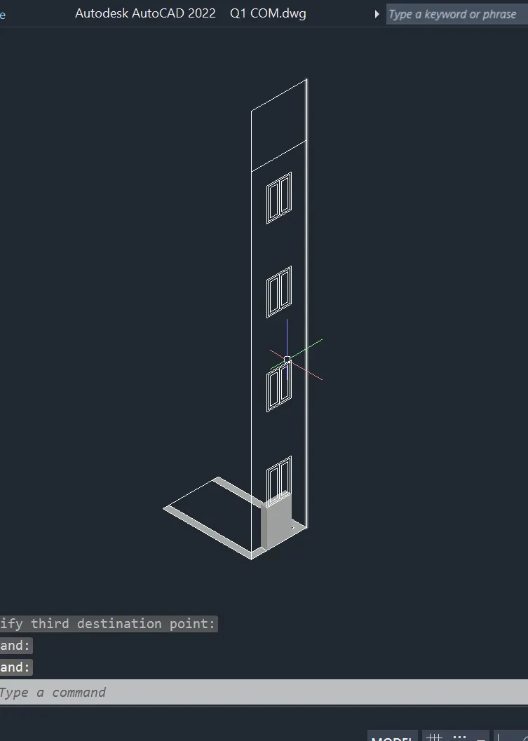
Align the elevation according to plan
Align> Specify first, second and third point >enter
Extrude the walls up to elevation height
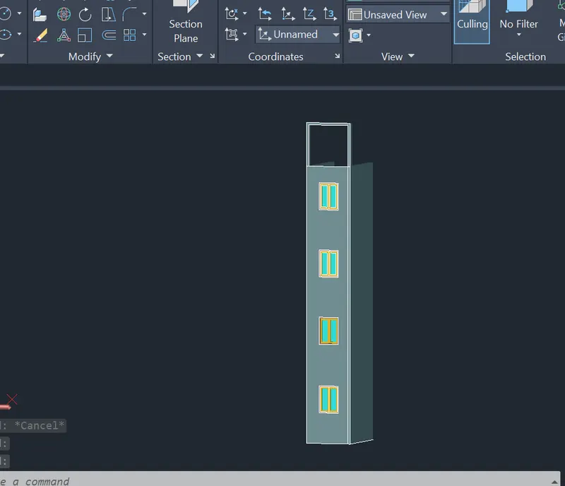
Extruding the window
- Layer > 3d frame > set to current layer
- Extrude the frame up to 3”
- Layer > 3d mullion > set to current layer
- Extrude the mullion up to 2”
- Layer > 3d glass > set to current layer
- Extrude the glass up to 0.5”
- Move the windows up to 1” from wall
- Offset the top line of the elevation up to 9” downwards
- Offset the wall up to 4”
- Create boundary
- Extrude up to 9"
Result:
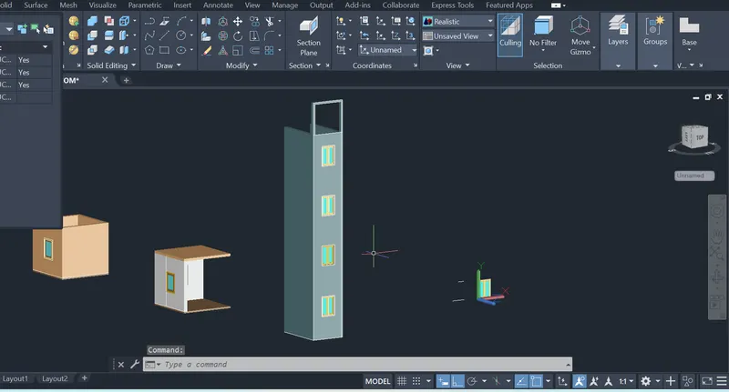
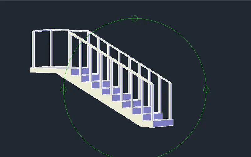
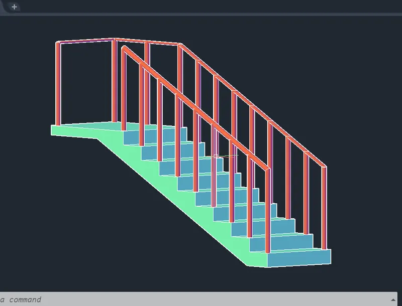
Aim & Introduction: To create the ismoteric 3d view of a stair with railing as shown in the plan and elevation.The size of the balustrades and the hand rails are assumed.
Commands used:
- Rectangle
- Line
- Explode
- Extend
- View
- 3D orbit
- Boundary
- Extrude
- Union
- Subtract
- Align
- array
Procedure:
- Open new drawing file
- Change the setting in to 3d modelling
- Change unit to engineering
- Change the dimension settings (D > Modify > primary units > engineering > set to current)
Creating plan
- Rectangle > specify point >12’ ,3’ > enter
- Offset > 1’>select the last rectangle > select inner side of the rectangle
- Array > select line > enter distance between line is 1’
Creating the side elevation
- Line >specify point > 6”
- Line >specify point > 9”
- Copy > select line as object > array> enter numbers > specify refrance point.
- Offset > select bottom treat > enter distance: 6”
- Offset > select bottom treat > enter distance: 4”
- XL >select bottom of the raiser and corner of threat.
- Offset >6” >select thr Xl line >spevify direction.
- Trim> select the lines to trim
- Align> select the first second and third points to the plan
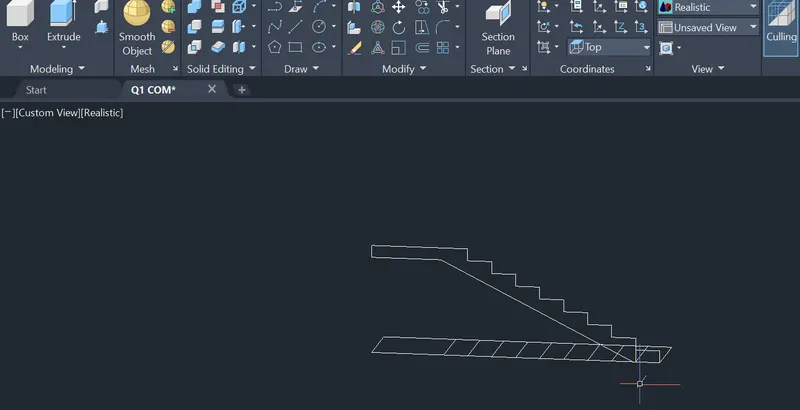
- Extrude the elevation
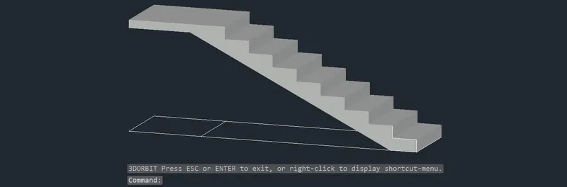
- Extrude > select the region > specify direction > enter distance:3’.
Creating a hand rail and balustrades
- Create a circle on above of treat copy the circles on another sides
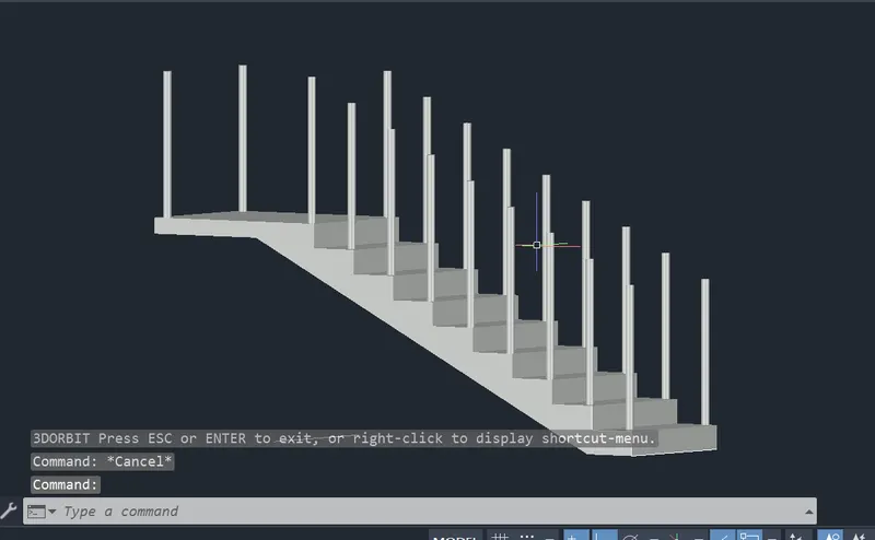
- Copy > select circle > specify another end of treat
- Do the same steps for all tert
- Extrude > select circles > specify distance > enter height :3’
- Draw the line above tret
- Sweep > select circle > select line as pathdo the above step for another side
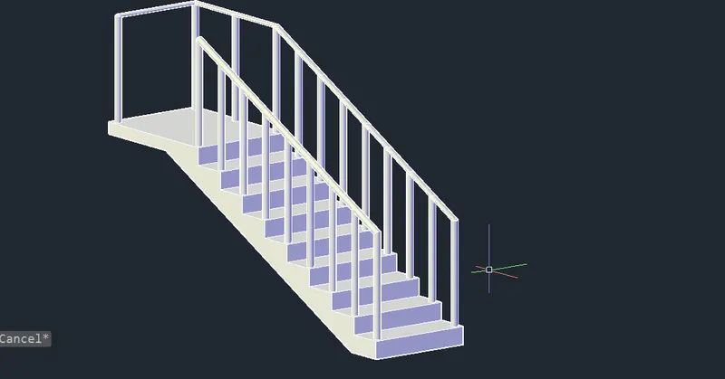
Result:
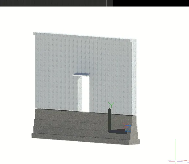
Aim & Introduction:To Create the 3D view of a Wall with spread footing. Create the Door opening only. the size the sizes of parapet and the coping are assumed. And also to create a rendered view of the model with materials as of your choice.
- Rectangle
- Line
- Explode
- Extend
- View
- 3D orbit
- Boundary
- Extrude
- Union
- Align
procedure :
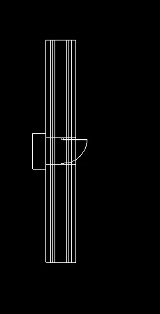
creating a plan
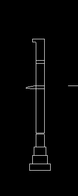
creating a section
Align the plan and section according to plan and extruding
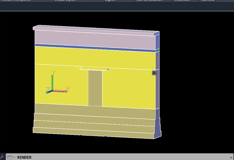
Assigning materials to the module
Rmat > select module >select material to assign
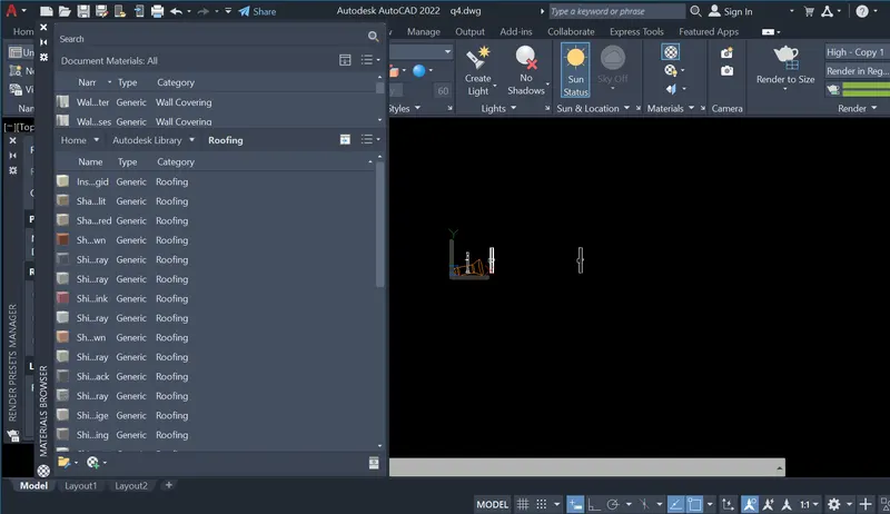
Result :
Rendering done upto level 3