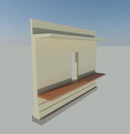
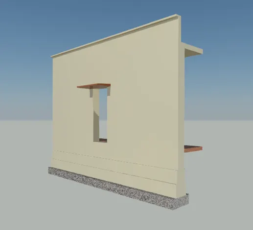
Creating 3D Isometric view of various structural elements in AutoCAD
3D ISOMETRIC VIEW OF THE BUILDING
Aim: To create a 3D Isometric View of the building with given plan and elevation in AutoCAD 3D modelling
Introduction: The 3D Isometric View of the building is created in AutoCAD using 3D modelling tool.
The main objective of this project is to understand about AutoCAD 3D, applying materials and rendering. AutoCAD is primarily used for generating 2D sketches. While it is possible to create 3D objects, AutoCAD is built around a flat, sketch-based interface. There is a wide range of pre-defined 3D objects in AutoCAD. These objects are cylinders, spheres and wedges and many more. But then users use 2D objects and modify them using the 3D commands accordingly. So, AutoCAD 3D commands like Extrude, Sweep, Revolve, Union are used by the users. Also, the user must know the importance of the Viewport feature if they are working on 3D Models. The viewport command allows the user to split the drawing area into different windows to project multiple views of the model. These include the top, front, left/right views of the object. This feature works great for the user and helps them to observe the model from different aspects.
The procedure of drawing is explained and the final results are given.
Commands Used:
Line
Rectangle
UCS
Dim linear
Region
Extrude
Subtract
Box
Units
Dimstyle
3Dface
3Dorbit
Hide
Explode
Move
Copy
Solid edit
Union
Boundary
3Dmirror
3Drotate
Erase
Plan
Procedure:
Open the AutoCAD, switch to 3D modelling by clicking on workspace switching and click on the home button near the view cube.
Type unit or UN in the command line and press enter
Set type of unit as engineering and precision as 0’ 0”
In insertion scale set unit as Inch.
Set upper limit and lower limit of the drawing
Set the limits and zoom - all.
Here first have to draw the wall using the line command, as shown in the figure.
Next, we have to draw the two windows of sizes of 3’ and 3'-2"
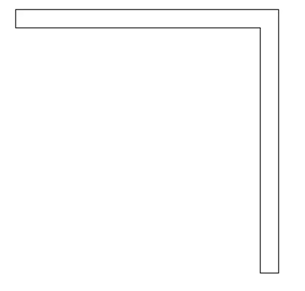
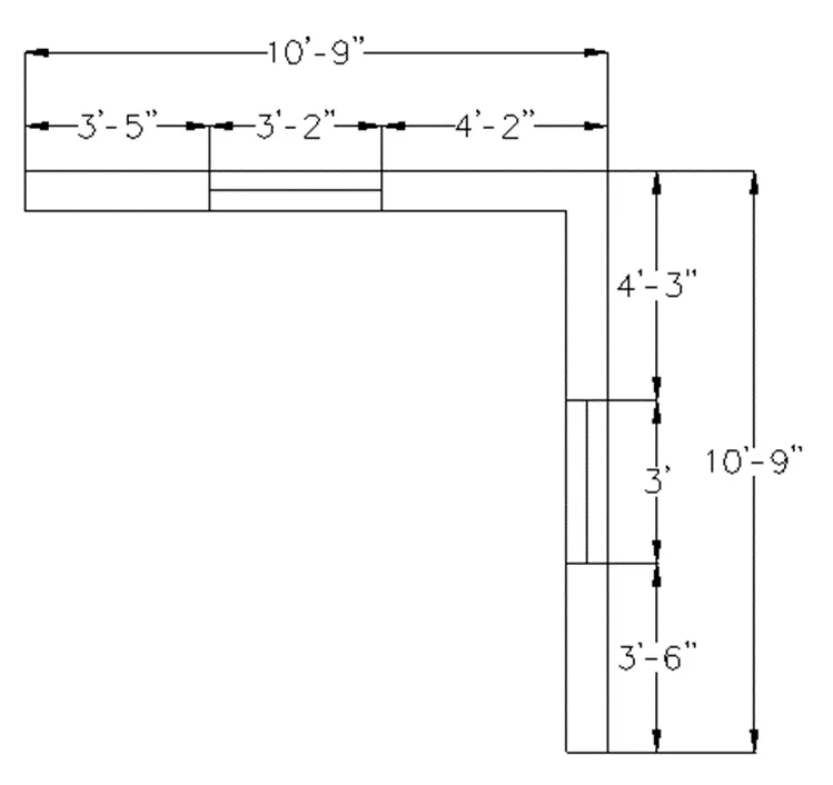
Change the view to 3D by clicking on home button of view cube
Set UCS as world
Use Press pull tool to extrude boundaries to total height of 10’
Draw rectangles at both windows and extrude them to height of 3’
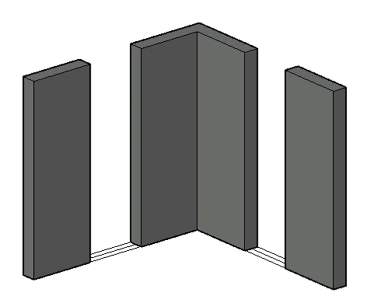
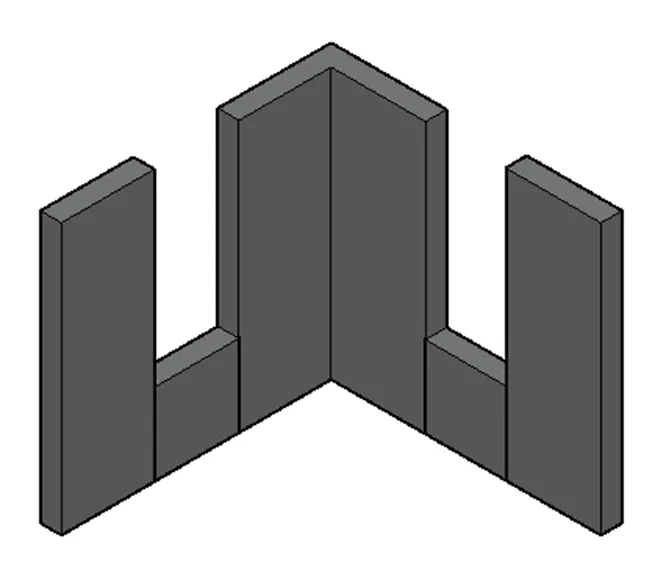
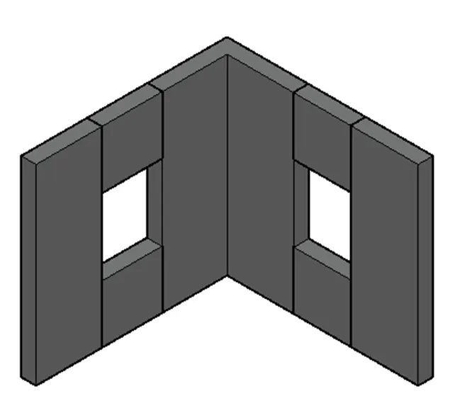
Draw rectangles at top of both window openings and extrude them downside to 3’ to provide window opening
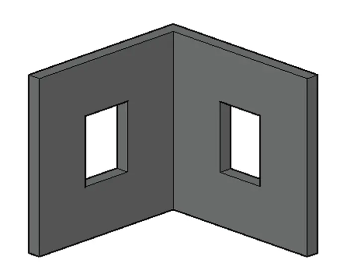
Select all the wall and use union command to them as single solid object
Creating Elevation Windows
Draw a rectangle of dimension 3’,4’
Offset the rectangle to inside to distance of 3”
Then offset the rectangle again inside to distance of 4”
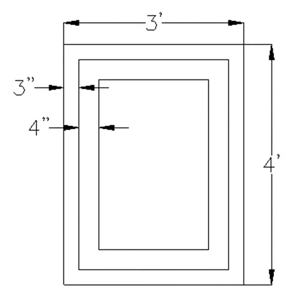
Start the boundary command and click on pick points
Click inside the window frame area and press enter
Type SUBTRACT command
Select the bigger region and then select the smaller regions to subtract them.
Follow the same procedure for all the three boxes.
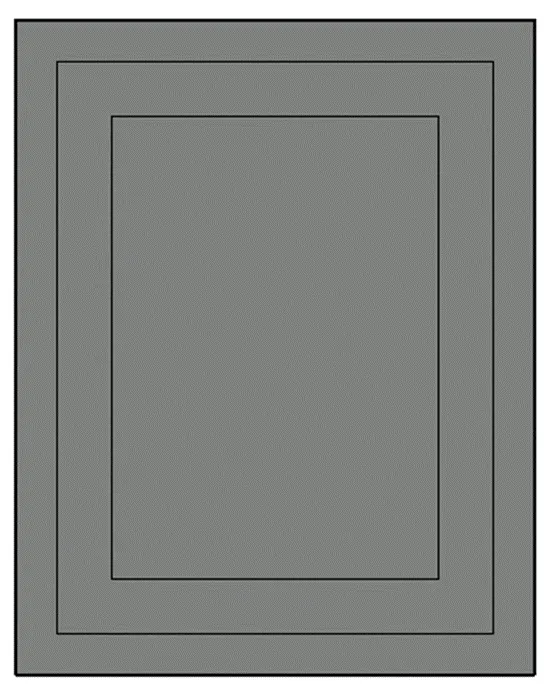
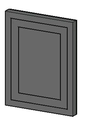
Now using the MOVE command place the window at the correct position as shown.
The floor and roof are created using extrudes command.
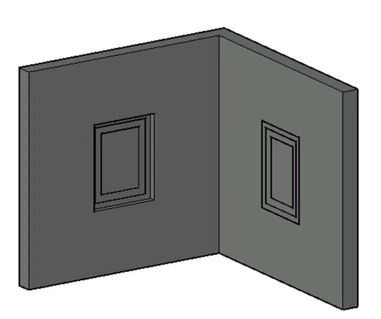
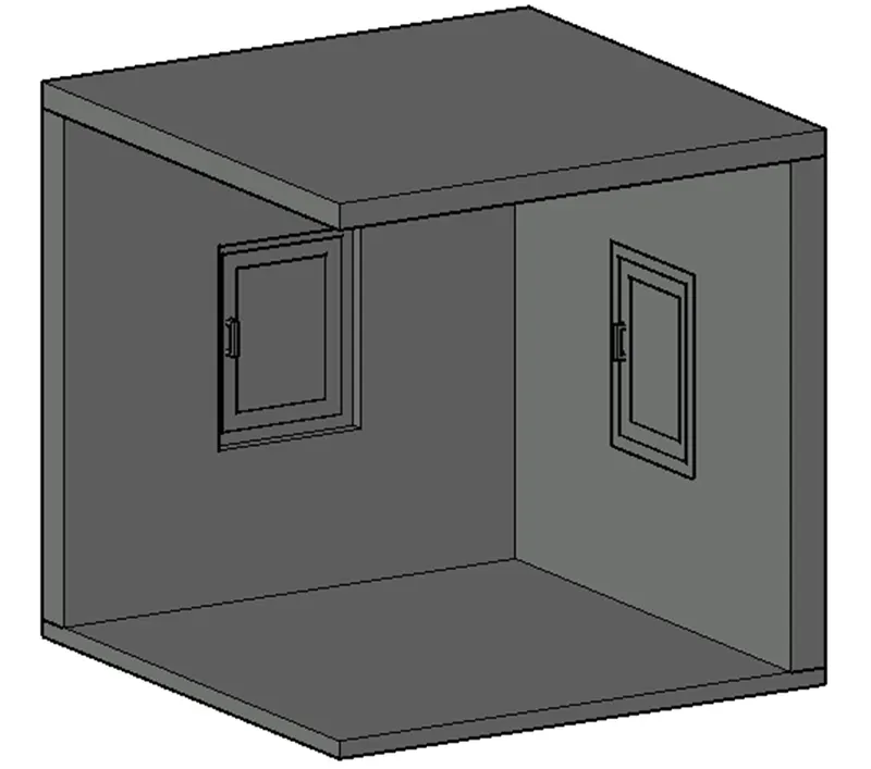
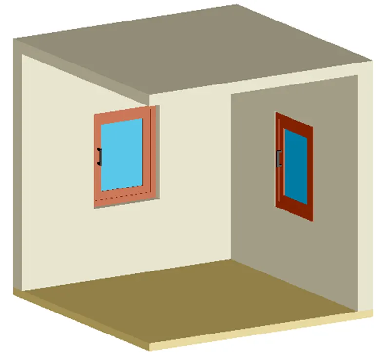
For the 3D model color applied to look better
RESULT
The 3D Isometric View of the building is created using AutoCAD 3D modelling
3D VIEW OF THE BUILDING FAÇADE
Aim: To create a 3D View of the Building Façade in AutoCAD 3D modelling
Introduction: The 3D View of the Building Façade in AutoCAD using 3D modelling tool.
The procedure of drawing is explained and the final results are given.
Commands Used:
Line
Rectangle
UCS
Dim linear
Region
Extrude
Subtract
Box
Units
Dimstyle
3Dface
3Dorbit
Hide
Explode
Move
Copy
Solid edit
Union
Boundary
3Dmirror
3Drotate
Erase
Plan
Procedure:
Open the AutoCAD, switch to 3D modelling by clicking on workspace switching and click on the home button near the view cube.
Type unit or UN in the command line and press enter
Set type of unit as engineering and precision as 0’ 0”
In insertion scale set unit as Inch.
Set upper limit and lower limit of the drawing
Set the limits and zoom - all.
Here first have to draw the wall using the line command, as shown in the figure.
Create the window opening of dimensions 3’ wide as shown in figure
Add dimensions using dimension tool
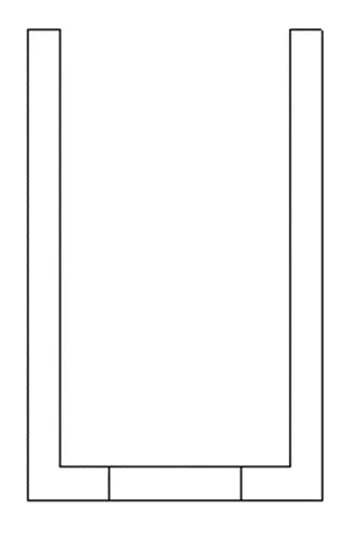
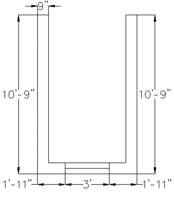
Change the view to 3d by clicking on home button of view cube
Set UCS as world
Set the view style control as SHADED
Extrude the boundaries created to total height of 40’10”
Type UCS in command line and select view to create user UCS
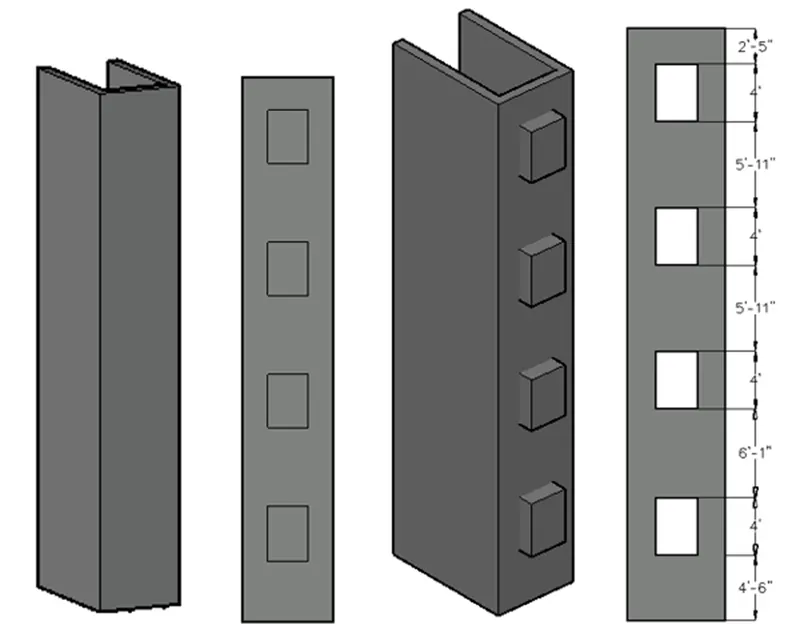
Then use rectangle tool to create window of size 3’,4’ and use copy to replicate
Use move tool to place the window at exact positions
Extrude the rectangle and use subtract the extruded solid to create window openings
Switch UCS again to view and use dimension tools to provide dimensions
Creating Elevation Windows
Type UCS and click on face and select the face having 3' wide window
Draw a rectangle of dimension 3',4'
Offset the rectangle to inside to distance of 2"
Offset the inside rectangle to inside at a distance of 3"
Add dimensions using dimension tool
Start the boundary command and click on pick points
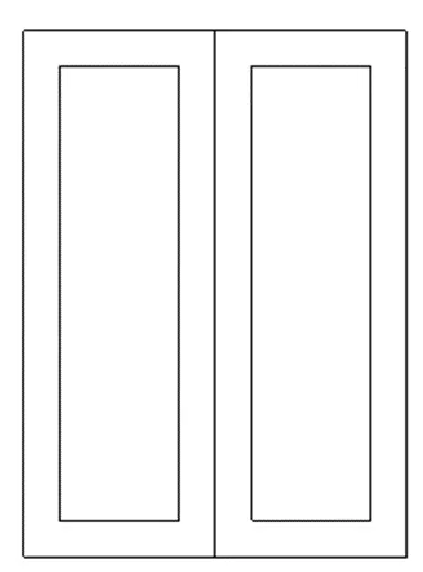
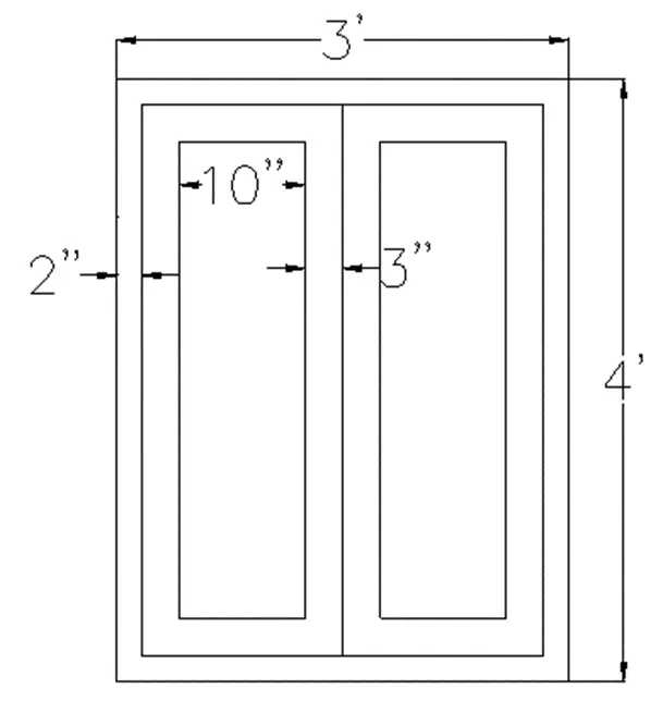
Click inside the window frame area and press enter
Type SUBTRACT command
Select the bigger region and then select the smaller regions to subtract them.
Follow the same procedure for all the three boxes.
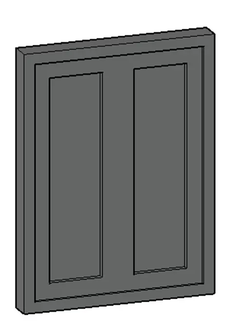
The upper part of building was then drawn using line command 4” wall with height 6’5” from top
Create a boundary for the wall
Extrude the boundary to 9” as shown in elevation
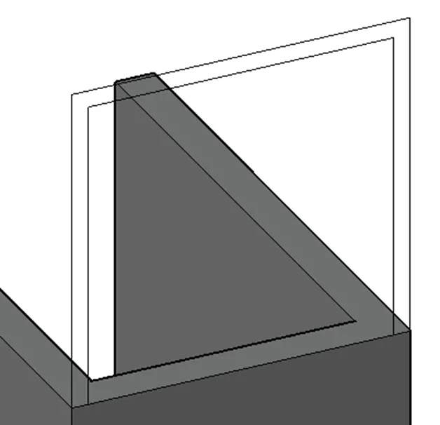
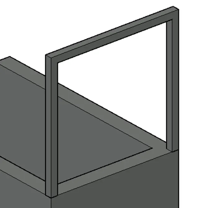
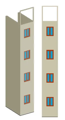
Now put the building facade in the 3d isometric view using the 3dorbit command as shown in the below figure.
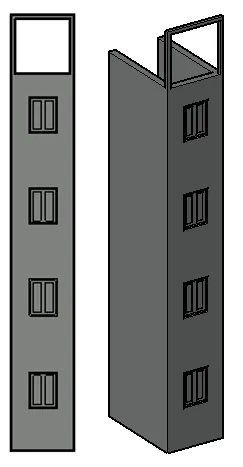
RESULT
The given 3d isometric view of the building facade is drawn successfully in the AutoCAD 3D modelling
3D VIEW OF A STAIR WITH RAILING
Aim: To create isometric 3D view of a stair with railing in AutoCAD 3D modelling
Introduction: The isometric 3D view of a stair with railing in AutoCAD using 3D modelling tool.
The procedure of drawing is explained and the final results are given.
Commands Used:
Line
Rectangle
UCS
Dim linear
Region
Extrude
Subtract
Box
Units
Dimstyle
3Dface
3Dorbit
Hide
Explode
Move
Copy
Solid edit
Union
Boundary
3Dmirror
3Drotate
Erase
Plan
Procedure:
Open the AutoCAD, switch to 3D modelling by clicking on workspace switching and click on the home button near the view cube.
Type unit or UN in the command line and press enter
Set type of unit as engineering and precision as 0’ 0”
In insertion scale set unit as Inch.
Set upper limit and lower limit of the drawing
Set the limits and zoom - all.
Change the view to 3D by clicking on home button of view cube and chance the view to right view
Set UCS to view
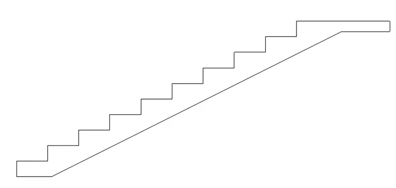
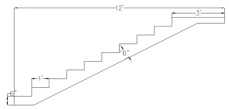
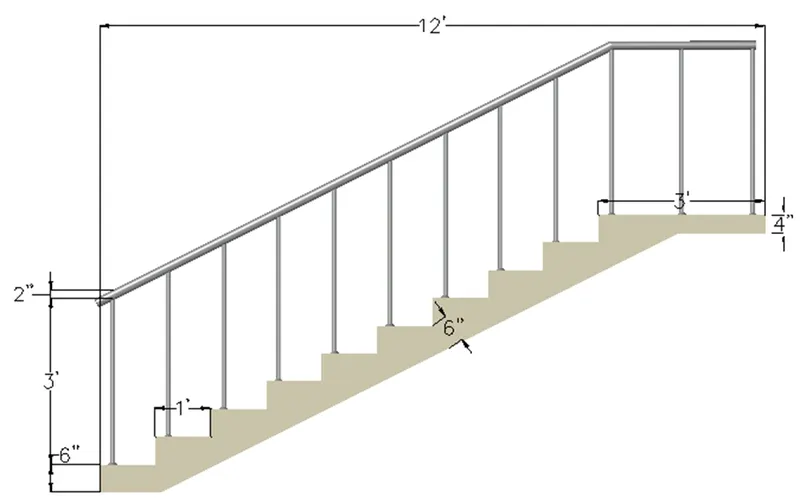
Use line command and draw a vertical line of length 6”
Draw a horizontal line of length 1’
Repeat the same process to create 10 steps, the 10th step is landing of 3’
After reaching 9 steps draw a landing of length of 3’
Provide dimensions using dimension tool
Change the view to 3d by clicking on home button of view cube
Set UCS as world
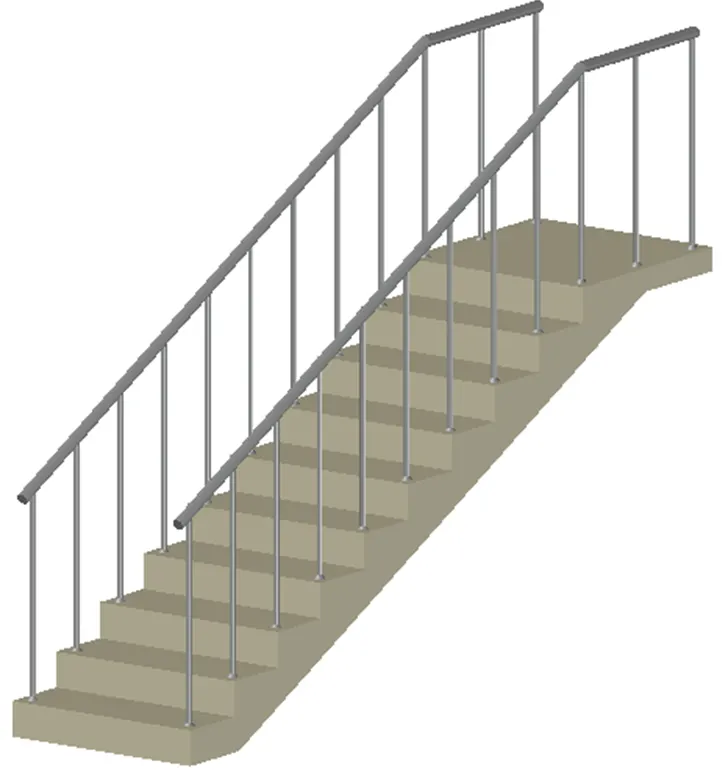
Set the view style control as REALISTIC
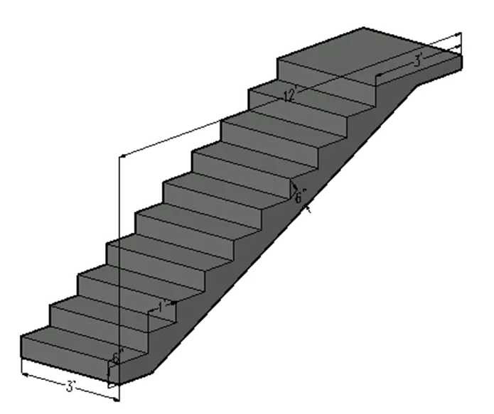
Create a region from the side view of the stairs
Extrude the side view to a distance of 3’ as shown in figure
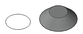
Draw circle of diameter 0.5”
Extrude the circle and select taper
Provide taper angle as 45 and height as 0.5”
Use Presspull and extrude to 2’11.5” to create circular baluster
Use move tool to place it on tread
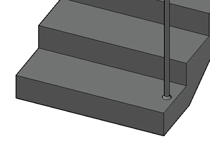
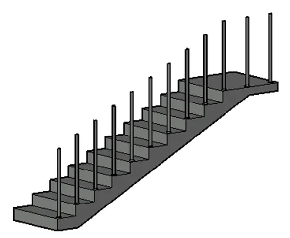
Use copy tool and place it on every steps
Draw a polyline connecting all the top edges of hand rails.
Draw a circle of diameter 2" on top of the hand rail.
Create a region of the circle drawn and do a Sweep command.
Select the circle as object to sweep.
Select the poly line drawn as path of sweep as shown in figure
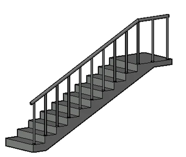
Copy the same and place them at equal intervals as required.
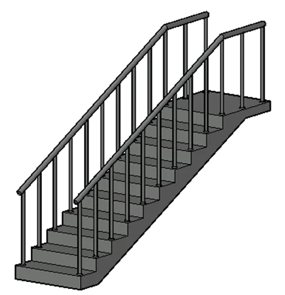
For the 3D stair model apply color for better visibility
RESULT
The given 3d isometric view of the stair is drawn successfully in the AutoCAD 3D modelling
3D VIEW OF A WALL WITH SPREAD FOOTING
Aim: To create 3D view of a Wall with spread footing in AutoCAD 3D modelling
Introduction: The 3D view of a Wall with spread footing in AutoCAD using 3D modelling tool.
The procedure of drawing is explained and the final results are given.
Commands Used:
Line
Rectangle
UCS
Dim linear
Region
Extrude
Subtract
Box
Units
Dimstyle
3Dface
3Dorbit
Hide
Explode
Move
Copy
Solid edit
Union
Boundary
3Dmirror
3Drotate
Erase
Plan
Procedure:
Open the AutoCAD, switch to 3D modelling by clicking on workspace switching and click on the home button near the view cube.
Type unit or UN in the command line and press enter
Set type of unit as engineering and precision as 0’ 0”
In insertion scale set unit as Inch.
Set upper limit and lower limit of the drawing
Set the limits and zoom - all.
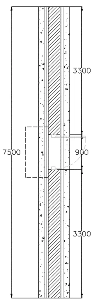
Draw plan of wall with spread footing with given dimensions as shown in the below figure
Using the line command, the Plan and section was drawn.
All the respective materials like dimensions, walls, door etc. was placed in the same layer.
Hatch commands of texture and pattern was used for hatching
Using the DIMLIM command the dimensioning was completed
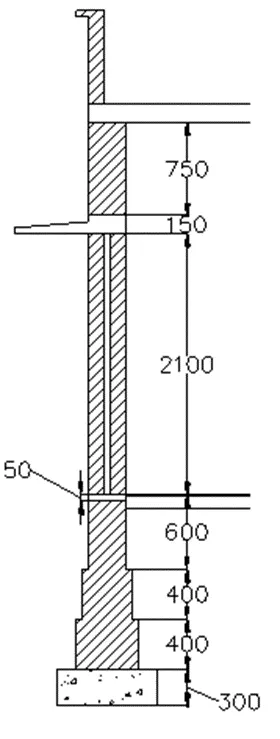
Copy section drawing to draw the 3D
The south west isometric view is made the default view.
Rotate the section using 3drotate to 90
Type BO to open the boundary command
Click on the internal portion of footings and walls and press Enter
Click on the extrude option from the home tab.
Specify extrude height 7500 and press Enter
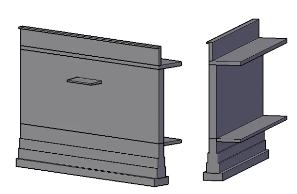
The rectangle command, extrude command and subtract command was used to provide opening for wall.
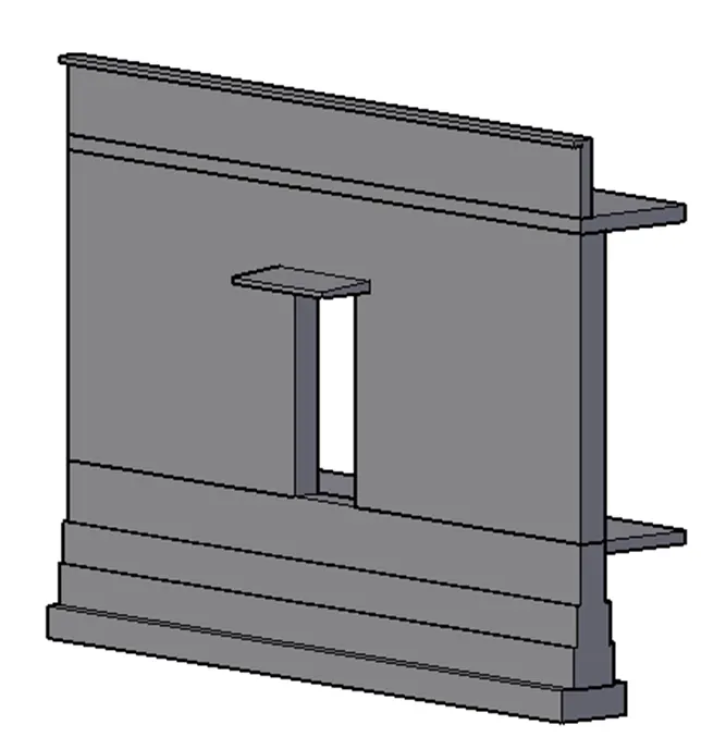
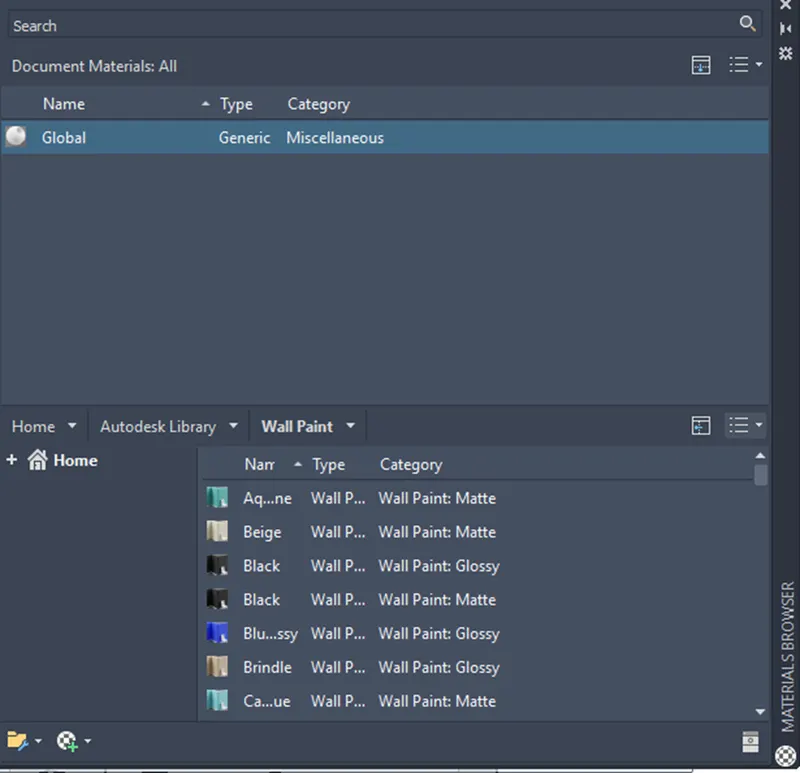
The 3d model was applied with different materials from Autodesk material library respectively for individual parts like sun shade, doors, footing and parapet etc.
Now place the camera and put it in the required position and then press enter.
Enable sky background and turn on Sun for lighting and shadows
Finally, we select the render option and then slowly it changes to the rendering view as shown in the below figure.
Save the image after completion of rendering
RESULT
The 3D view of a Wall with spread footing is created and rendered view of the model with materials is attached