Creating 3D Isometric view of various structural elements in AutoCAD
1,
AIM: TO Create the 3D view of the Building Plan and elevation.
INTRODUCTION:
- Using of various commands and tools such as subtract,slice, 3d mirror, 3dmove, assigning materials, rendering and creating cameras, fixing lights was introduced.
- In order to create the 3d view of building plan, the commands used were polysolid, rectangle, extrude, subtractand otherdrafting tools.
PROCEDURE:
- Set the units of the sheet such as Engineering type.
- Set the limits of the sheet and strat drafting.
- Using polysolid from top view create the wall of the dimensions of width 9inches, heigth of 10 feets.
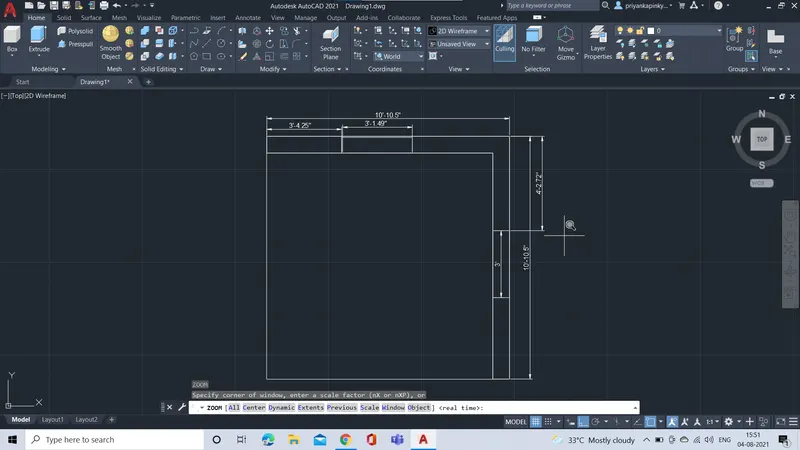
- Using the rectangle create the floor area such as create the region using REGION command.
- Then to draft the window openings create the rectangle on the surface ot the walls.
- Then using extrude command, extrude the rectangle box on the surface of the wall.
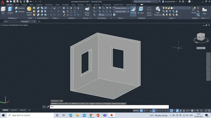
- Using the subtract command, subtract the rectangle portion from the wall surfaces, which form the window openings.
RESULT:
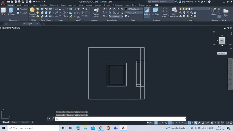
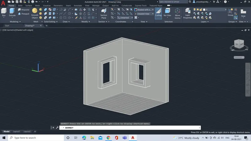
3D VIEW OF BUILDING PLAN CREATED.
2,
AIM: TO Create the 3D view of the Building Facade as given in the plan and the elevation.
INTRODUCTION:
- Using of various commands and tools such as subtract,slice, 3d mirror, 3dmove, assigning materials, rendering and creating cameras, fixing lights was introduced.
- In order to create the 3d view of building Faceade, the commands used were polysolid, rectangle, extrude, subtractand otherdrafting tools.
PROCEDURE:
- Set the units of the sheet such as Engineering type.
- Set the limits of the sheet and strat drafting.
- Using the polysolid from top view, create the facade of the building.
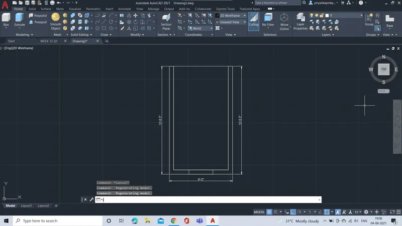
- Insert the rectangle box as the window opening with width 9inches and heigth as 4inches.
- Using the extrude command, extrude the rectangle from the isometric view.
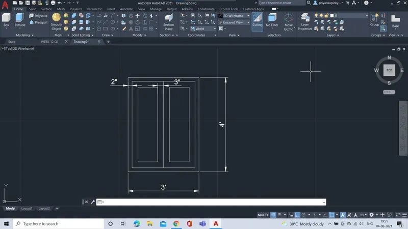
- Then create the elevation of the buliding using line command or polyline command.
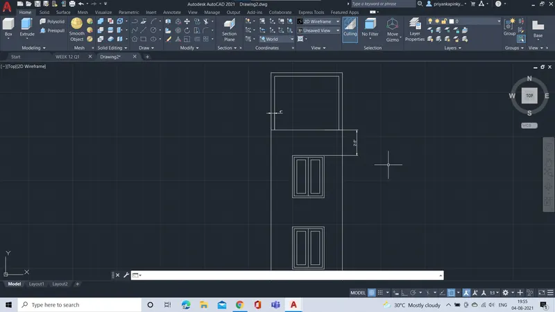
- The create the detail of the window using rectangle command, line command and offset command.
- Using Region command, make surface and exrude the window.
RESULT:
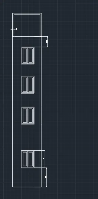
THEREFORE, BUILDING FACADE WITH PLAN AND ELEVATION HAS CREATED.
3,
AIM: TO create the isometric 3d view of the staircase with railing.
INTRODUCTION:
- Using of various commands and tools such as subtract,slice, 3d mirror, 3dmove, assigning materials, rendering and creating cameras, fixing lights was introduced.
- In order to create the Isometric 3d view of the staircase , the commands used were polyline, line, extrude and sweep commands were used.
PROCEDURE:
- Set the units of the sheet such as Engineering type.
- Set the limits of the sheet and strat drafting.
- Using the polyline from the isometric view create the staircase.
- Create stair case of tread 1 feet and rise 6 inches.
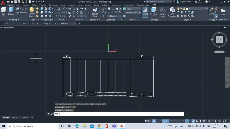
- Create the railing the staircase using circle on the surface of the thread.
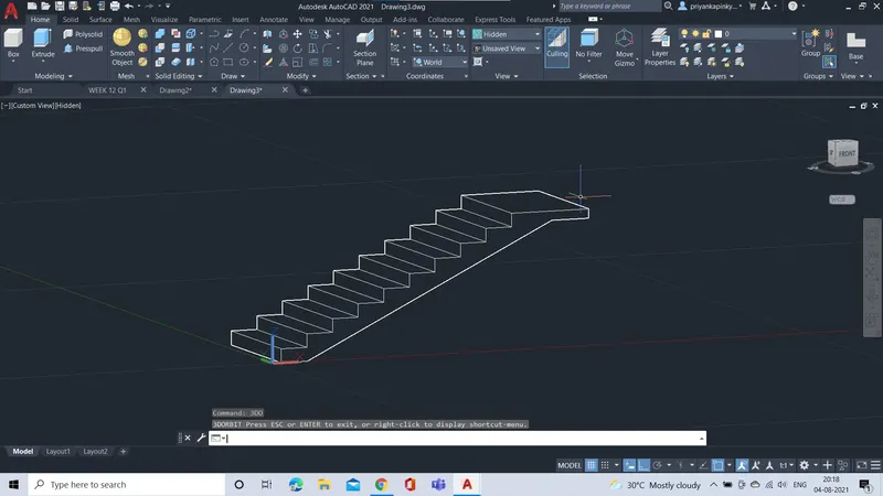
- Using the extrude command, extrude the circle to certain height and using copy tool, copy the railings where ever required.
- Using sweep command, create the railing horizontally in order to support the vertical railing.
RESULT:
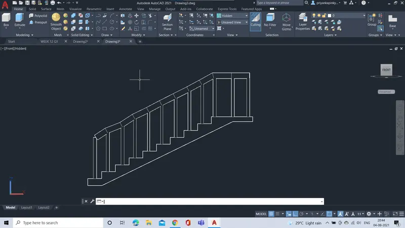
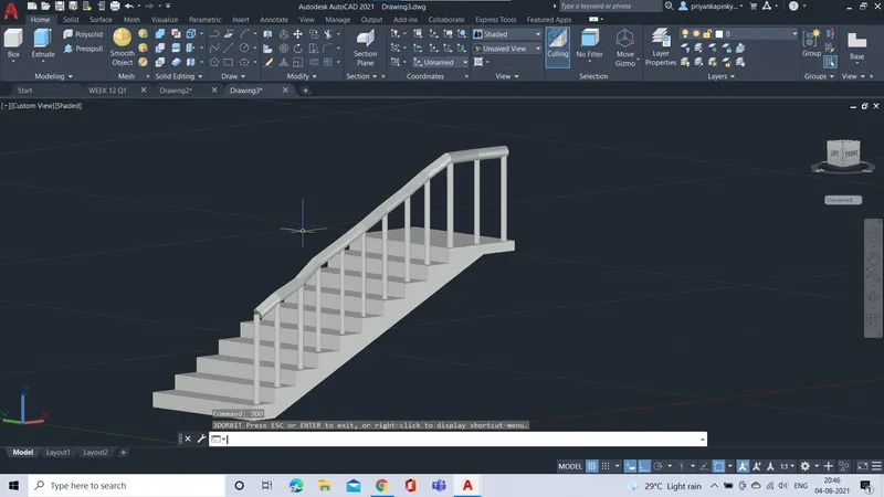
THEREFRE ISMERIC 3D VIEW OF THE STAIRCASE HAS CREATED.
4,
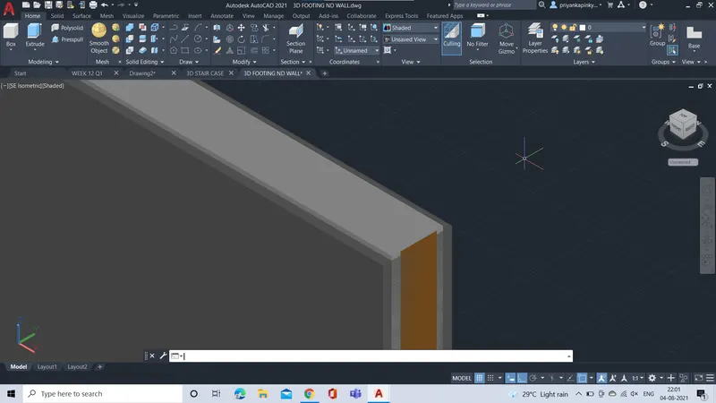
AIM: TO Create 3D view of the wall with spread footing.
INTRODUCTION:
- Using of various commands and tools such as subtract,slice, 3d mirror, 3dmove, assigning materials, rendering and creating cameras, fixing lights was introduced.
- In order to create the Isometric 3d view of the wall , the commands used were polysolid, line, extrude commands were used.
PROCEDURE:
- Set the units of the sheet such as Decimal type.
- Set the limits of the sheet and strat drafting.
- Using ploysolid from topview, create the wall of the given dimensions as given.
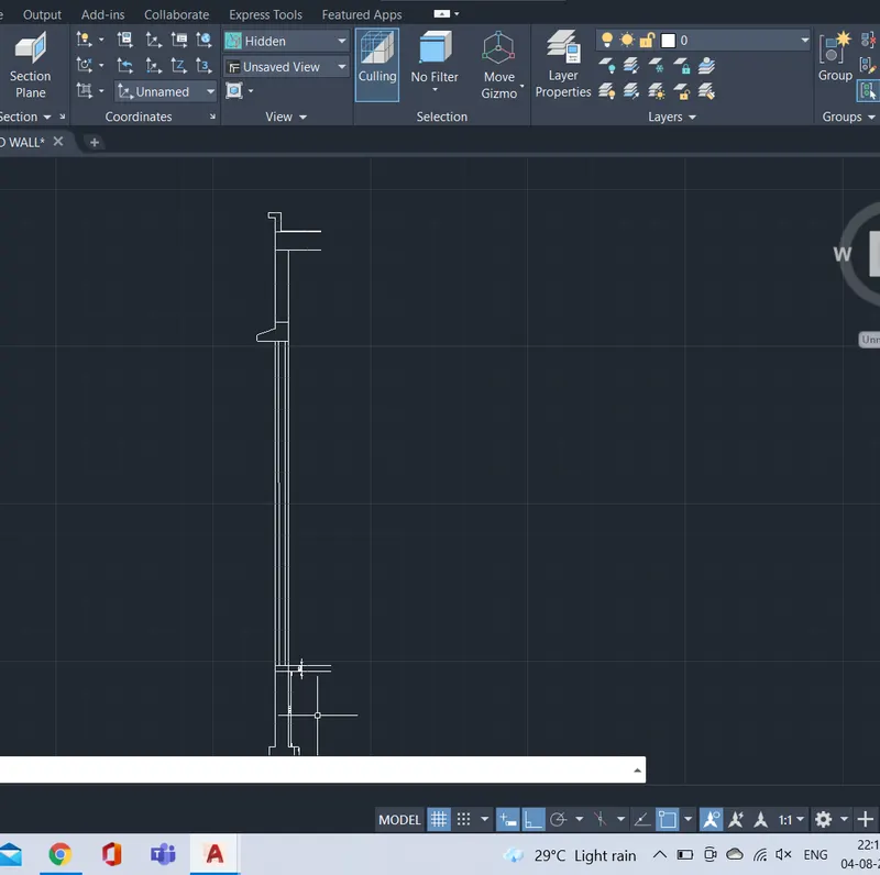
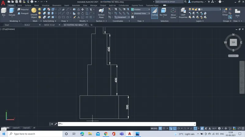
- Draft the sectional view of the wall using required drafting commands.
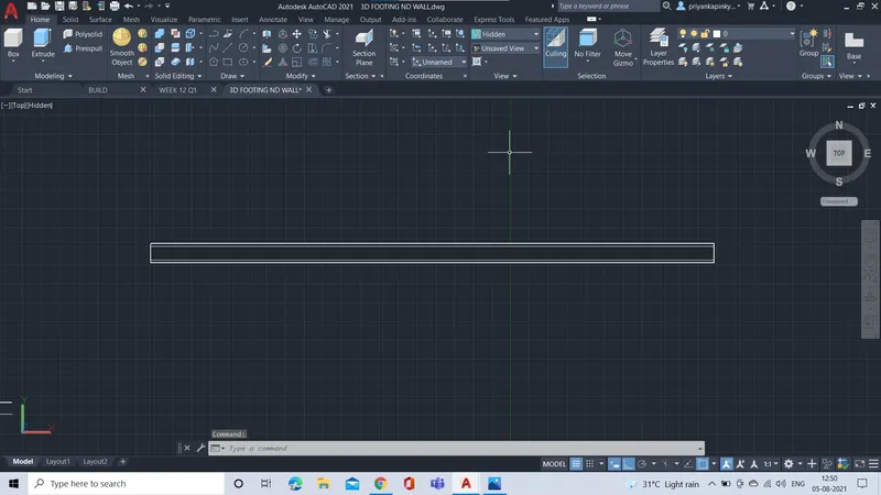
- Then using extrude command, exturde the wall and door inserted in the wall.
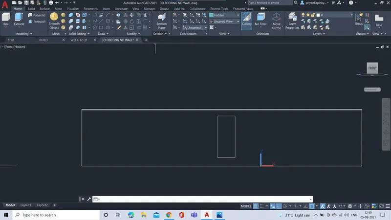
- Then using the line command from the top view, Create the section of the footing along with the wall.
- In order to create the spread footing along the wall, use line command and other drafting tools.
- For creating the materials in the wall use MAT command from the command prompt.
- Then from the materail library or from autodesk library>> select the type of material>> add to document >> select the object >> click on the assign material to the object.
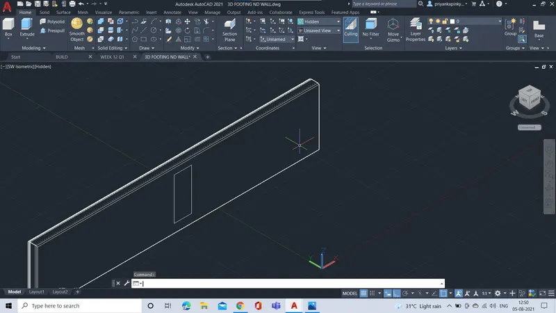
- In order to render, from visual command render the object by slecting any saved view.
RESULT:
THEREFORE THE 3D WALL WITH SPREAD FOOTING HAS CREATED.