Control the speed of DC motor using PWM technique
Aim-To control the speed of DC motor using the PWM technique.
Objective-By using the fan as a load and we have to get the Torque speed characteristics of the DC motor by use of PWM technique
Blocks Required-
Following blocks are used to develop the model
Pulse Generator, Controlled Voltage Source, Controlled PWM voltage, H-Bridge, DC motor, Ideal Rotational motion Sensor, Ideal Torque Sensor, Current Sensor, From, Goto, Solver Configuration.
Functions of the Used Blocks-
Pulse Generator-Pulse generator is used to provide the pulse for the reference signal to PWM controlled Voltage.
Controlled Voltage Source-It is used to provide the input voltage to the PWM controlled voltage.
Controlled PWM voltage-This block create the PWM output voltage across the PWM port to the input for the H-Bridge.
H-Bridge-The H-bridge circuit shows the H-Bridge motor driver.
Current Sensor-Current sensor is used to sense the current.
DC motor-DC motor is connected as a load across the H-Bridge.
Ideal Rotational Sensor-Ideal motion sensor is used to sense the any rotational motion.
Ideal Torque Sensor-Torque sensor is used to sense the torque.
Goto and From -Both the blocks are used to make the less complex model.
Model is as shown below-
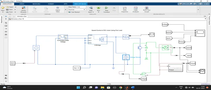
Working of the Simulink model-
1.By using the pulse generator we are giving the signal to the Controlled PWM voltage block through the controlled voltage source block. The input parameters to the pulse generator is as follow.
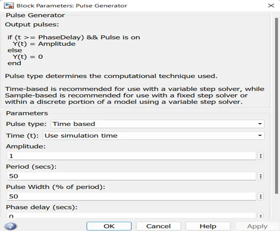
2.The pulse generator output is connected to the controlled voltage source. Control voltage source block represent or its operation is as ideal voltage source it can provide the same voltage at the output as input voltage irrespective of current flowing through the circuit.
3.Then Controlled PWM voltage block get the required signal at its reference port. PWM is nothing but the Pulse Width Modulation signal .The voltage across the PWM and REF port it crate the PWM voltage across the terminal.
- In PWM mode, the output is a PWM signal. In Averaged mode, the output is constant with value equal to the averaged PWM signal. The output of the PWM Voltage Controlled block is given to the input to the H-Bridge. Input to the Controlled PWM voltage block is as follow.
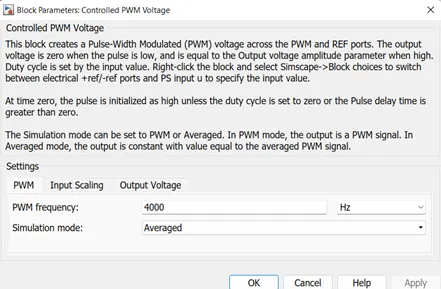
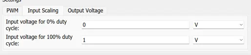
And output voltage will be 5 V.
5.H-bridge shown in the circuit is simple H-Bridge motor driver circuit. Output of the this H-bridge is totally depends upon the input voltage comes at the PWM port.
- If the input signal has a value greater than the Enable threshold voltage parameter value, the H-Bridge block output is on and has a value equal to the value of the Output voltage amplitude parameter. If it has a value less than the Enable threshold voltage parameter value, the block maintains the load circuit using one of the following three Freewheeling mode options
- Via one semiconductor switch and one freewheeling diode
- Via two freewheeling diodes
- Via two semiconductor switches and one freewheeling diode
- The signal at the REVport determines the polarity of the output. If the value of the signal at the REVport is less than the value of the Reverse threshold voltage parameter, the output has positive polarity; otherwise, it has negative polarity.
8.H-Bridge has six terminals are as follow
PWM, REF, REV, BRK, Positive voltage, Negative Voltage
9.Input parameters of H-bridge is as follow
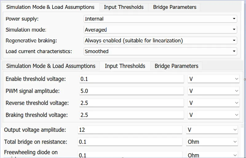
10.After the H-Bridge through the current sensor supply goes to the DC motor. DC motor have the four terminal positive and negative supply terminal and R and C are mechanical ports which shows the mechanical motions.
11.The DC motor torque speed relation are as follow
T=VK/R-wK2/R
The DC motor parameters are as follow shows in attached Image.
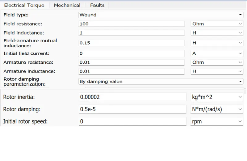
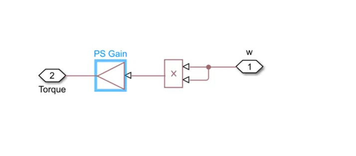
12.The fan load subsystem model is look like as follow
Where in put to the gain we have to put the value as below
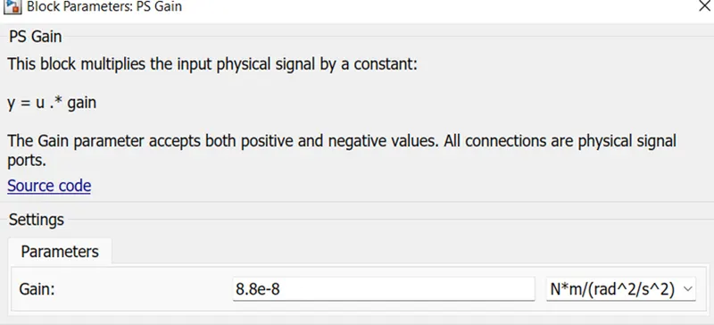
13.In our model we used fan as load where in fan load the motor torque is directly proportional to the speed. By implementing the above we can get the result.
And plot the XY plot which is speed torque curve which verify the above condition.
Please refer below output graph of speed torque
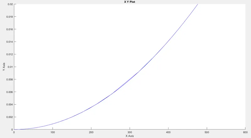
Above graph shows the speed on X axis and torque on Y axis.
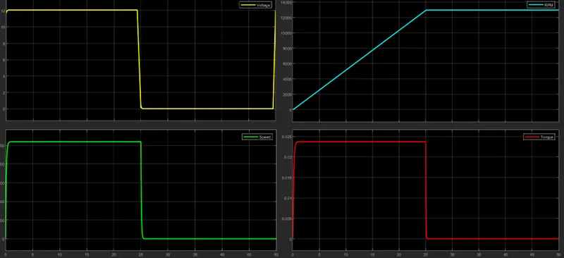
14.The below output graph of the speed, RPM, Input voltage to the motor and torque of the motor are as below.
Conclusion-
We verify the speed torque relation of the DC motor by implementing above model.
We verify the equation Torque is directly proport