Week - 4
- Implement control logic of a “washing machine” using Stateflow as per given sequence:
- If the power supply is available, the system gets activated
- If the Water supply is not available, stop the process & indicate through LED
- Soaking time should be 200s followed by Washing time of 100s.
- Then rinsing happens for next 20s & dryer runs for 50s
After all the processes have completed turn on the finished LED
Ans-
Working principale of washing machine-
A washing machine use centrifugal force to wash the clothes in washing machine motor runs at 800-1600 rpm to wash and soap the cloths.After wards same process is carried out for drying and soaking.
Process happen in washing machine-
1.Soaking-
In soaking clothes are dip in soap water for a certain time to remove the dirt from the cloths.
2.Rinsing-
In rinsing dirty soapy water is drained then the washing machine is refilled . And excess water from clothes are removed.
3.Drying-
Here warm dry air is passes through your cloths to dry fast removed the moisture.
For impementing the above question we required following blocks
1.Toggle Switch
2.Constant
3.Chart
4.Display
5.Lamp
Function of the block
1.Toggle switch- It is used to toggle the input.
2.Constant-It is used to give the input to the system.
3.Display-It is used to show the output.
4.Lamp-Lamp is to incade the which operation is going on
Please refer following diagram to implement the above logic
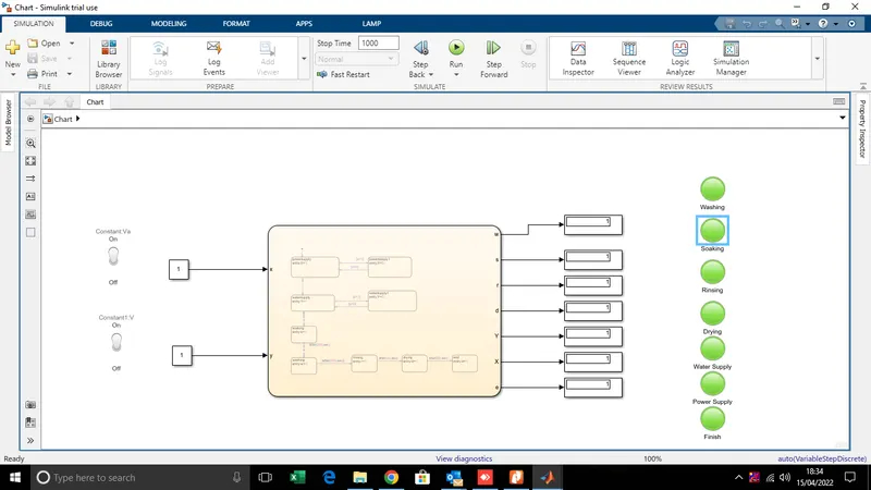
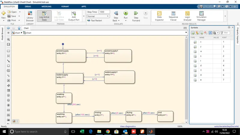
And to design the stateflow analysis following logic is used as per above mention considition following is the stateflow chart.
After process is completed signal is given by the lamp.
2. Make a Simulink chart for the “Gear shift” logic as per below conditions:
Speed Range(kmph) Gear
0 to 15 1
16 to 25 2
26 to 40 3
41 to 60 4
Above 61 5
Give speed input while the simulation is running & display the gear number.
Ans- To implement the above condition firstly we have to understand the mechnism as the speed increases we have to increase the gear as well in gear mechanism for manual transmission includes a shaft axial movable for selecting shift planes and rotable engaging gear defining shift plane.
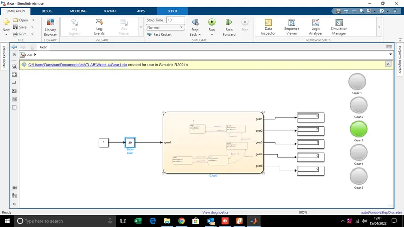
Following blocks are used to implement the above question
1.Constant
2.Slider Gain
3.Chart
4.Display
5.Lamp
Function of blocks used
1.Constant-To provide the input
2.Slider Gain-To cahnge the speed of model
3.Chart-To implement the stateflow logic
4.Display -To display the output
5.Lamp-To indicate the output.
Please refer the below block diagram to implement the logic
Please refer below stateflow block diagram to implement the above logic
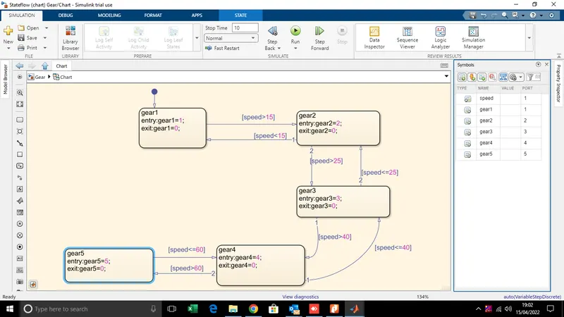
Thats how we are able to implement the gear shift logic.