Final Project: Design of an Electric Vehicle
Aim-
To make a simple and low run time vehicle model using individual component models.
Objective-
By using the simple block which is available in MATLAB we have to develop the simple vehicle which take less time for simulation and we will get the idea of a vehicle.
Blocks Required-
Drive cycle, Longitudinal driver, Controlled voltage source, Controlled PWM voltage, H-bridge, Current sensor,
Controlled current source, DC motor, Tire Magic Formula, Vehicle Body, PS to Simulink converter
Function of the Block-
Drive Cycle-It is used for the input parameter for the longitudinal driver which is as per our road condition simply it is graph between the Speed and time for different road condition.
Longitudinal Driver- Longitudinal driver is the block which shows the simulated driver which is work as similar to the actual driver.
Controlled Voltage Source-It is used to provide the signal to the PWM voltage block.
Controlled PWM voltage-this block is used for supplying the PWM signal to the H-bridge.
H-Bridge -H bridge here simply it is DC motor driver.
DC Motor-Permanent DC motor is used for the propulsion system.
Vehicle Body-It represents the two-axle vehicle body.
Tire magic formulae-It represents the tire of vehicle.
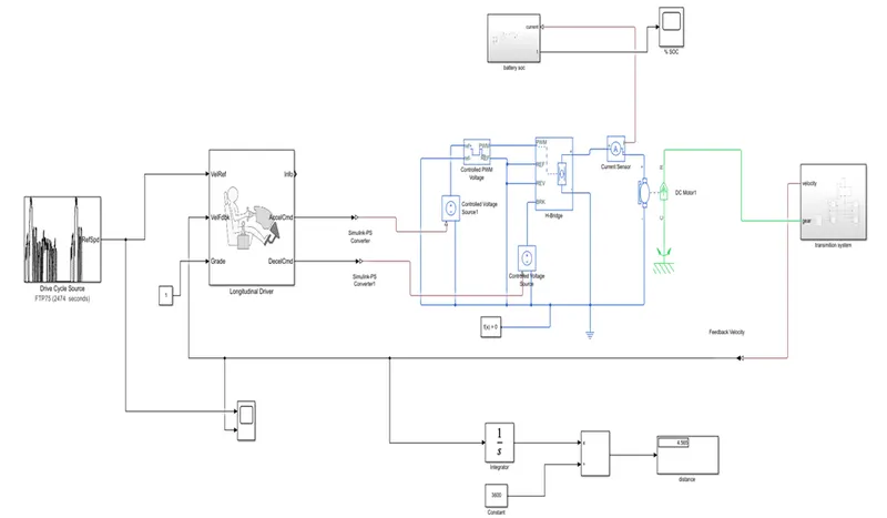
Model of the EV Vehicle is as shown below-
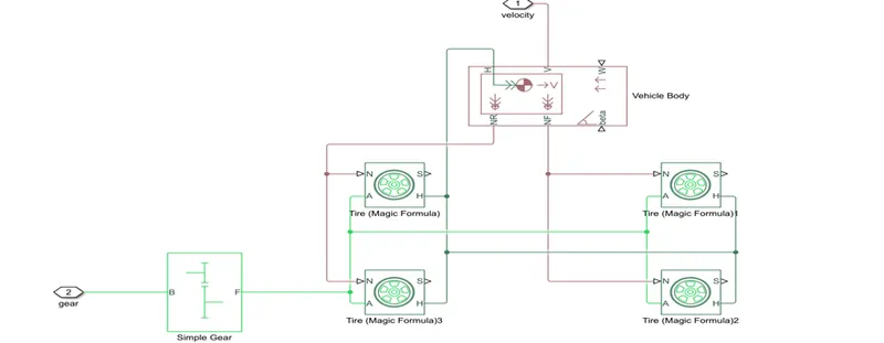
The transmission system subsystem model looks like as follow-
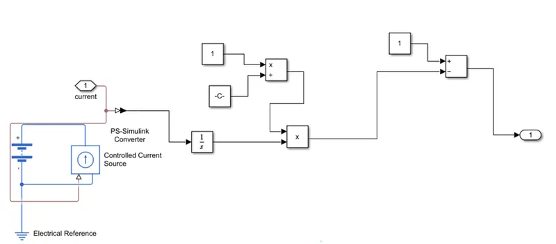
And SOC subsystem is looks like as follow-
Working of the model is as follow-
1.We have used FTP 75 drive cycle as our input to the vehicle. The driver cycle input is given to the longitudinal driver which is simulated driver which works as actual driver.
2.Longitudinal driver is getting the supply from the driver cycle. Longitudinal driver has 6 ports Velocity reference, Velocity feedback, Grade, Deceleration Command, Acceleration Command and info.
3.Where velocity ref is connected to the output of the drive cycle, velocity feedback is connected to the feedback signal of the vehicle which comes from the transmission system. To control the speed of vehicle and to monitor the vehicle speed PI controller is used.
4.Grade is a road grade angle which shows the grade of road, Acceleration command gives signal for acceleration, similarly the deceleration command works as a brake which is connected to the H-bridge brake port and simultaneously it works as regenerative braking.
5.Longitudinal driver gives signal for accelerating and braking to the H-bridge and taking the signal from the Velocity feedback and reference velocity.
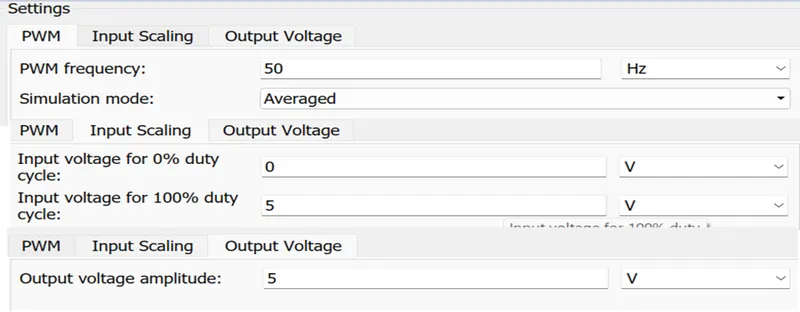
6.Later on the signal goes toward control PWM voltage block through the controlled voltage source in that signal converted to the controlled PWM voltage. Means it convert normal signal to the Pulse Width Modulated Signal and it gives input to the H-Bridge inverter.
7.Controlled PWM voltage block have four terminal ref+, ref-, PWM and REF it compares the signal with two ports ref+ and ref- and gives output then PWM port is connected to the PWM of H-Bridge and the Ref is connected to the REF.
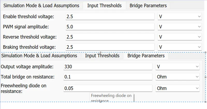
8.Then output of the Controlled PWM voltage is connected to the H-bridge where PWM port is connected to the output port of the Controlled PWM voltage and Ref port is connected to the ref port of H-Bridge. The H-Bridge is nothing but the motor driver cycle or we can say it is converter which works in two quadrants.
9.Where Ref port and Rev Port are connected to the each other and fourth port is BRK which indicates the while we give signal to the BRK port vehicle start decelerating. And from positive negative port it gives supply to the motor.
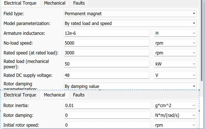
10.After getting signal to the motor, Motor start running. Motor also has the 4 terminals where two are the supply terminals positive and negative. Other two are R and C port where R terminal is connected to the gear shift and C port is connected to the mechanical rotational reference to sense the rotational motion of the motor.
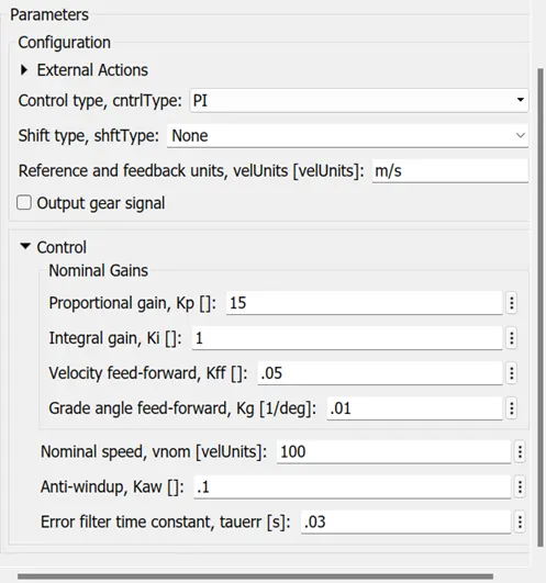
Below is the input for controlled Longitudinal Driver Block
For PWM controlled Voltage have the below inputs
H-Bridge has the following Input
The DC motor have the following parameters
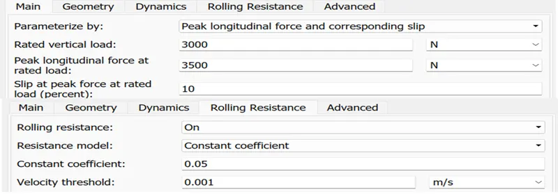
11.Look into the transmission system subsystem we have used four-wheel drive where as a tire we used tire magic formula the input to the tire magic formula as follow
12.For simulation in place of vehicle we used the vehicle body which work as vehicle in simulation environment. The parameter for the vehicle body is as follow
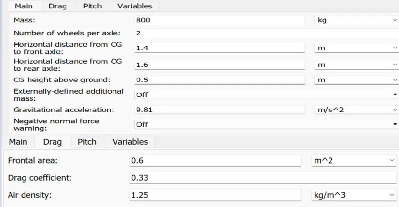
13.Tire magic formula have four ports as A denotes mechanical rotational port. H-denotes the mechanical translational port. N is a physical signal port that applies to the normal force which is connected to the reverse and forward port of the Vehicle body. S denoted the tire slip.
14.Vehicle body has the four ports NR, NF, Beta, H, V, W. Where H denotes the mechanical translational port
Associated with horizontal rotation of the body, NR and NF denotes the rear and front forces of the vehicle V is velocity of the vehicle and W and Beta are the Wind speed and inclination angle of the road resp.
15.Later on look in to the battery soc system it is very simple and calculated as per the coulomb formulae
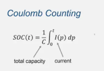
By using this we calculate the soc of the battery. We can calculate the battery capacity by using Ah which we assign to the battery.
16.By connecting the gain we can calculate the % SOC.
The result of the simulation is as follow-
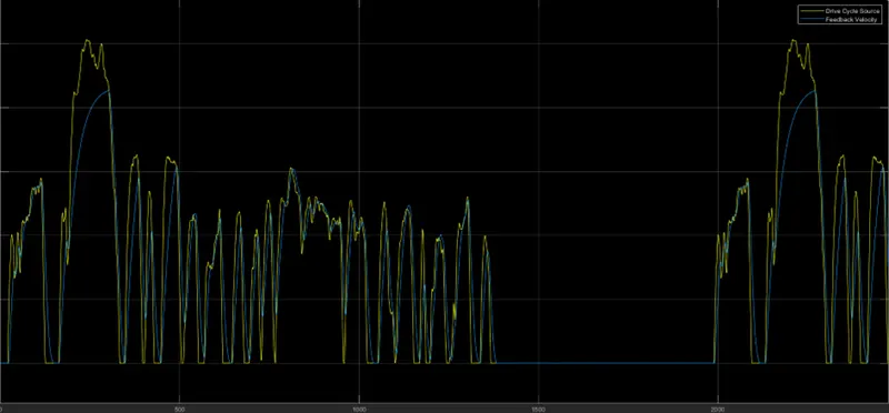
For the velocity of the vehicle and the drive cycle. Where drive cycle velocity and vehicle velocity match each other and we have connected the velocity feedback port to the vehicle velocity it becomes the closed loop system and monitor itself. Vehicle velocity traces the drive cycle graph as shown below.
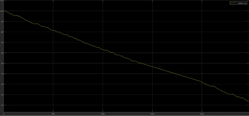
Below graph shows the output of the SOC graph in which we can see that as the vehicle start covering the distance battery state of charge start discharging and at the end of simulation the battery state of charge is near about 15%.
Conclusion-
We run the simulation and we got the result the drive cycle graph and velocity of vehicle graph traces each other by using the closed loop system they maintain their motion.
Battery state of charge i.e., SOC of battery is 15% at the end of simulation.