Week-7 Challenge: DC Motor Control
1. A. Explain a MATLAB demo model named ‘Speed control of a DC motor using BJT H-bridge
Ans- In this model they are using the BJT as a switch in H bridge Inverter
Construction of H bridge-
1.The model contain H bridge of 4 switched which are BJT's ( Bipolar junction Transistor ).
2.And as we know when BJT use for power switching application then it behave likes an IGBT.
3.The load is connected between the switches which look like a H shape as shown below.
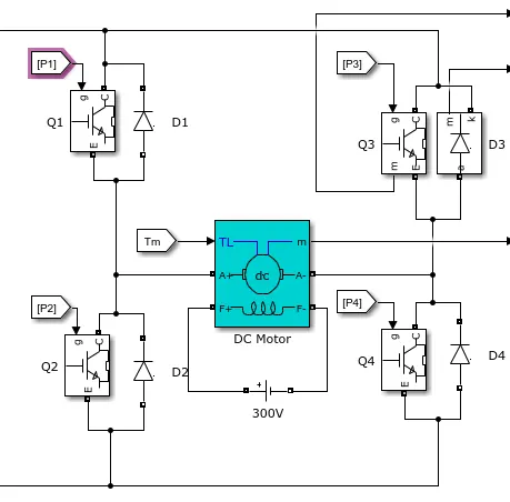
4.The top end of bridge is connected to the battery and bottom end is connected to the ground.
5.The four switch can be operated independently by their respective gate signal( by triggering the gate signal).
Operation of the H-Bridge Inverter-
Case 1st- Q1 & Q4 is On and Q2 & Q3 is off
In this case current start flowing through from Q1 it get feeded to the DC motor from left lead and grounded from the Q4 switch .
The direction of current as shown below.
In above case motor start rotating in forward direction.
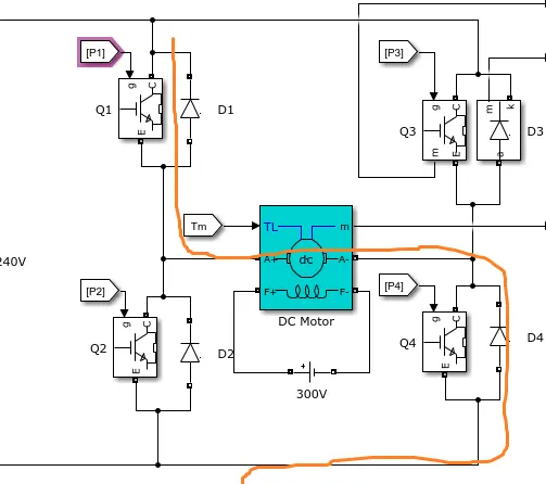
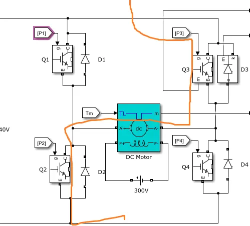
Case 2-Q2 & Q3 is on and Q1 & Q4 is off.
In this case current start flowing through the Q3 to the motor and grounded from the Q2 switch
The direction of current flows is as shown below
In this condition motor energise in reverse direction so motor start running in the reverse direction.
In this Inverter we can not operate when with the following condition Q1 & Q2
Description of model speed control of DC motor using H-bridge
The Model is as shown below
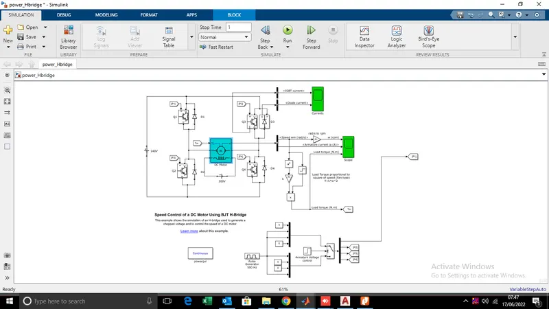
1.In this model DC motor preset model is used of specifications are as follows 5HP 240 V 1750RPM. It is simulated as fan type load .
2.The H-bridge consist of BJT diode simulated as an IGBT.
3.Diodes are also used in the model D1 D2 D3 & D4.
The simulation results are as follows
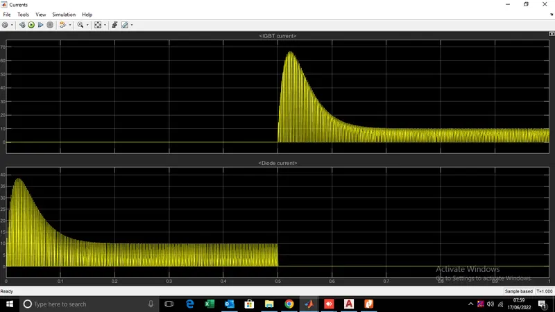
Following results are of IGBT and Diode Currents
Below result shows the angular speed ,armature current and load torque
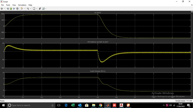
From the waveform of armature current we can see that at starting their is sudden spike increase in current at osec and at 0.5sec .
As voltage of motor changes the speed of motor can get changes.
Transition from positive to negative we can see that sudden surges in the armature current .
B. Comment on the armature current shoot-up from the scope results.
The waveform of speed armature current and load torque is as shown below
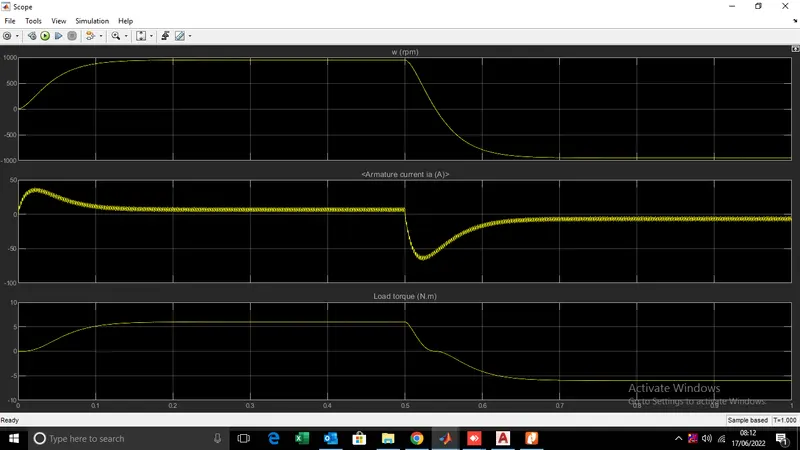
From armature current graph we can seen that at starting their is sudden spike increase in current also at 0 Sec and at 0.5 Sec.
Mean from positive to neagtive direction of rotation we can see the sudden surges this is due to transient switching occur at 0.5 sec of each duty cycle.
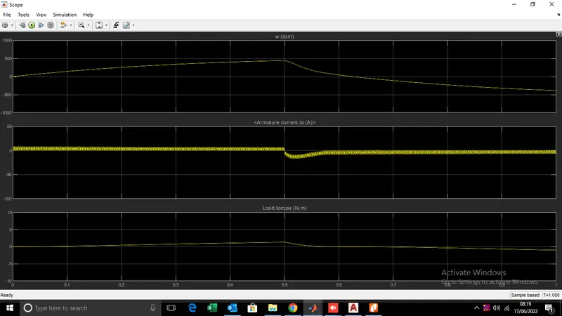
Ans we can reduced the sudden surges by reducing the duty cycle.
In aboe case the duty cycle is 75% if we make it 50% the current surges can be reduced.
Below graph shows the result with 50% of duty cycle.
C. Refer to the help section of ‘The Four-Quadrant Chopper DC Drive (DC7) block’. Compare it with the H-bridge model
Ans-The below block shows the four quandrant DC to DC chopper.

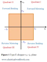
This DC drive can work on four qundrants( Forward motoring,Reverse regeneration,Reverse motoring and forward regeneration.And main advantage of this drive due to high switching frequency the armature ripple current is very low.
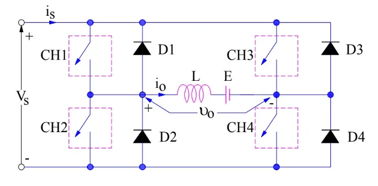
The block diagram of DC to DC chopper is as shown below
Construction of DC to DC chopper-
Four qundrant chopper contain four switches CH1 to CH4 and four diodes D1 to D4.
And DC motor .All this connected in antiparallel way as shown above.
Operation of DC to DC chopper-
First Qundrant Operation(Forward Motoring mode)-
In first qundrant operation ,first condition CH1 and CH4 is on and current flows through the CH1 to inductor and then to Ch4 and it completes the Circuit and gives the positive waveform and motor runs in the forward direction. In second condition of first qundrant CH1 is off and CH4 is on in this condition current flows through the CH4 through the diode 2and likewise it complete the circuit.Thus in first qundrant the output is Positive.
Second Qundrant Operation(Forward regeneration mode)-
In second quadrant operation ,in first case CH 2 is on the current flows from the inductor CH2 and then from the Diode 4 and like wise it comletes the circuitr in this condition output is Voltage is positive and current is negative .In second case CH2 is off and the current flows from the diode 2 inductor and diode 1 and likewise it complete the circuit.
Third Qundrant Operation(Reverse Motoring mode)-
In third qundrant operation CH3 is in operated condition and chopper CH2 is in on condition the current flow from the CH3 motor and then CH2 and it completes the circuit in this condition output voltage and current both are negative.In second condition of third qundrant the CH3 is off and CH2 is still on the current flows from the CH2 and D4 and likewise it completes the Circuit as in this condition armature current is negative so it operated as regenerative mode.
Fourth Qundrant Operation(Reverse regeneration mode)-
In the fourth qundrant in the first condition the CH4 is on in this condition the current flows from the CH4 diode D2 and the motor like wise it complete the circuit.And in this condition the current is positive and voltage is negative.And second condition of the forth qundrant CH4 becomes in this condition the current flowing through the Diode D2 motor and Diode D3 and like wise current complete its path and output current is positive and the voltage is negative.
Comparison-
1.The Four qundrant DC motor works on all the four Qundrant operation are as below
A.Forward motoring
B.Forward Braking
C.Reverse Motoring
D.Reverse Braking
And H bridge BJT works only in two mode
A.Forward Motoring
B.Reverse Motoring
2.In four qundrant chopper the switching frequency is very high duw to which aramture current spikes is low.
While in BJT h bridge switching frequency is low due to that the armature current spike is very high.
3.For reversing or forwarding the motor we dont have to change the terminal the direction of signal can be changed to reverse and forwarding the motor.
While in other type we have to chenge the terminal.
4.H bridge is used in robotics application while the DC to DC chopper is used in industrial applications.
2. Develop a 2-quadrant chopper using simulink & explain the working of the same with the relevant results.
Ans-
Two Qundrant chopper-
As name indicate the this choppr is operated in two qundrant.In first qundrant it offers the motoring mode because its armature current and voltage is positive.In second qudrant it
operates as a regenerative braking mode as armature current get reversed and the voltage remains positive.Basically the two quandrant chopper is work as in motoring mode and
regenerative mode.
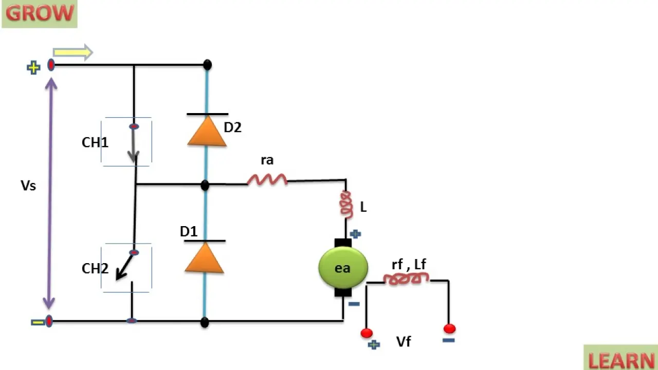
In this chopper the two switches and two diodes are used where as diodes are used as for the freewheeling operation.
The constructional diagram of two quandrant chopper is as below.Where CH1 and D1 is conduct at same time and CH2 and D2 conductd on same time.
1.Motoring Mode-
1st condition CH1 is closed current flows from source to voltage through the inductor and in this operation the inductor start storing the current as the CH1 gets off the cuurent flows from
the inductor to the armature and from diode 1 it completes its path.As in this conditin the current flowing from the sourece to load the current is positive and output is also positive so we
can say thet it is operated in first qundrant.
2.Reverese Braking-
1st condition of this mode is when CH2 is operated the supply volyage can not give the supply voltage hence current flows as inductor stores a charge then current flows from inductor to
the CH2 in this condition armature current gets reverse.Ans 2nd condition as CH2 gets off then current flows from load to source in this condition curent remins reversed direction.
The same circuit we have plotted on the Mtlab and gets the result as below.
Model is as below
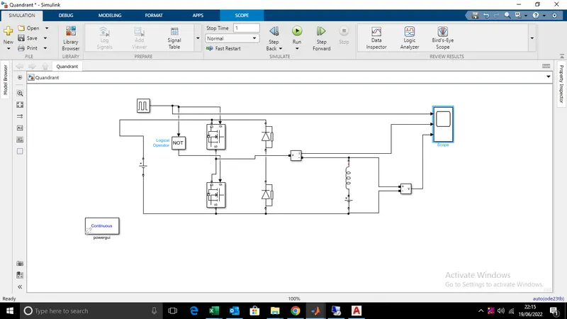
In this model we have used the mosfet as a switch diodes for freewheeling operation .Inductor as load and in series of inductor we have used the DC source as Load.
Pulse generator is used to provide to trigger the Gate of the mosfet and not operator is used to provide the inverted signal to other switch. So that both the switches can not be able to
operate at the same time.
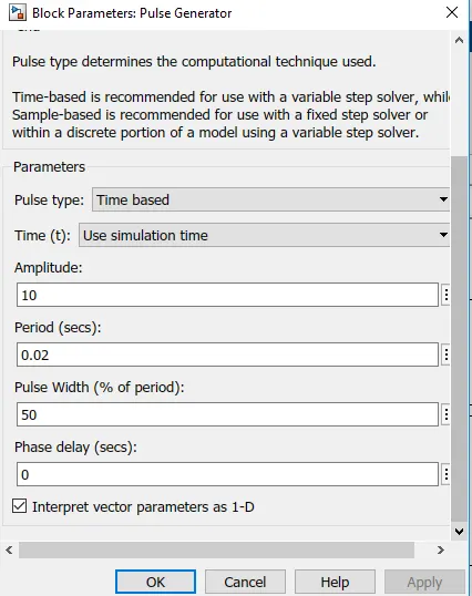
In pulse generator block we have set the parameter as below amplitude is 10 period is 0.02 and pulse width is 50%.
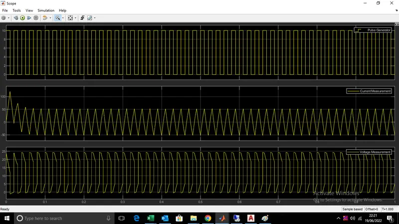
After simulating the model we have get the following result which is as discussed above.
3. Explain in a brief about operation of BLDC motor-
Ans-
A brushless DC electric motor (BLDC motor ), also known as synchronous DC motor, is a synchronous motor using a . Idirecct currentt uses an electronic controller to switch DC currents to the motor windings producing magnetic fields which effectively rotate in space and which the permanent magnet rotor follows.The controller adjust the phase and and phase of DC current pulses to controll the speed and torque of the motor.
Unliked conventional brushed typed DC motor wherein the brush make the elctrical contact with the commutator on the rotor so has to amke the electrical path between armature and DC source.BLDC motor employs the electrical commutation with permagnet rotor and stator with a sequence of coil in this motor permagnet rotor current carrying conductor are fixed.
The armature coil are switched electronically by transistor or SCR with correct the rotor position in a such way that armature field is in space quadrature with rotor field poles .Hence the force acting on the rotor cause it rotates.Hall sensor are used to detect the rotor positioned.
Hall Sensor or rotary encoders are the most commonly used to sense the position of the rotor and are positioned around the stator. The rotor position feedback from the sensor helps to determine when to switch the armature current.This electronic commutation arrangement is used to eliminate commutator brushesh and reliable less noisy operation.Due to absesnce of brushesh it can run at high speed at an efficiency of 85 to 90 percent.
Construction of BLDC motor-
BLDC motors can be constructed in different physical configurations. Depending on the stator windings, these can be configured as single-phase, two-phase, or three-phase motors.
Construction of BLDC motor is very similar to the induction motor as well as the conventional DC motor.
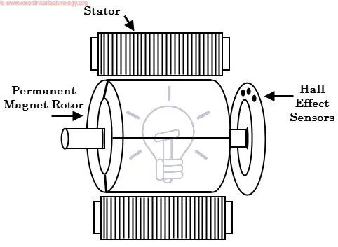
Stator-
Stator of a BLDC motor made up of stacked steel laminations to carry the windings. These windings are placed in slots which are axially cut along the inner periphery of the stator.
These windings can be arranged in either star or Delta. However, most BLDC motors have three phase star connected stator .
Each winding is constructed with numerous interconnected coils, where one or more coils are placed in each slot. In order to form an even number of poles, each of these windings is
distributed over the stator periphery.
Rotor-
BLDC motor incorporates a permanent magnet in the rotor. The number of poles in the rotor can vary from 2 to 8 pole pairs with alternate south and north poles depending on the
application requirement. In order to achieve maximum torque in the motor, the flux density of the material should be high. A proper magnetic material for the rotor is needed to produce
required magnetic field density.
Working of BLDC motor-
BLDC motor works on the same principle as conventional DC motor i.e when current carrying conductor placed in a magnetic field experiances a forece. As a consequences reaction force m
magnet experiances a force.In case of curent carrying conductor is stationary and permanent magnet is moving.
When the stator coils are electrically switched by a supply source, it becomes electromagnet and starts producing the uniform field in the air gap.
Though the source of supply is DC, switching makes to generate an AC voltage waveform with trapezoidal shape. Due to the force of interaction between electromagnet stator and
permanent magnet rotor, the rotor continues to rotate.With the switching of windings as High and Low signals, corresponding winding energized as North and South poles. The permanent
magnet rotor with North and South poles align with stator poles causing motor to rotate. Observe that motor produces torque because of the development of attraction forces
(when North-South or South-North alignment) and repulsion forces (when North-North or South-South alignment). By this way motor moves in a clockwise direction.
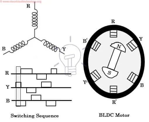
Hall sensor is used to determine the shaaft positioned to electronic controller for switching and likewise the motor is rotate.On the feed back signal is decides which coil is to be engize.
Below figure shows the switching sequences and how coils are energize.
Advantages of BLDC motor-
1.It has no mechanical commutator and associated problems.
2.High efficiency due to the use of permanent magnet rotor
3.High speed of operation even in loaded and unloaded conditions due to the absence of brushes that limits the speed
4.Smaller motor geometry and lighter in weight than both brushed type DC and induction AC motors
5.Long life as no inspection and maintenance is required for commutator system
6.Higher dynamic response due to low inertia and carrying windings in the stator
7.Less electromagnetic interference
8.Quite operation (or low noise) due to absence of brushes
Disdvantages of BLDC motor-
1.These motors are costly
2.Electronic controller required control this motor is expensive
3.Not much availability of many integrated electronic control solutions, especially for tiny BLDC motors
4.Requires complex drive circuitry
5.Need of additional sensors