Conjugate Heat Transfer Analysis on a graphics card.
AIM: To perform conjugate heat transfer analysis on a graphic card.
INTRODUCTION: In this challenge, I have conducted a few tests on the given model by changing the mesh size and changing the inlet fluid flow direction. The fluid properties are air and the temperature of the air is 300k.
THEORY: Initially, I have used a basic mesh size of 14 mm. The heat generated by the processor is 46875000`W/M^3`.
CALCULATION:
Heat Generated = P/V
- The heat generated by the processor is 3 W.
- The volume of the processor is 0.008*0.008*0.001= `6.4*10^-8 M^3`
- P/V = `3/(6.4 *10^-8)` = `46875000 W/M^3`.
GEOMETRY SETUP:
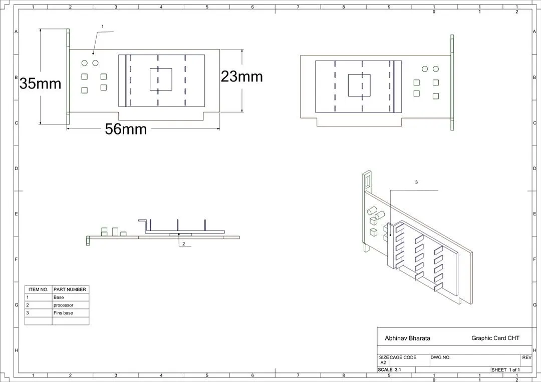
- The model has the following components Processor, Cooling Fins, PCB (which includes electronic components)
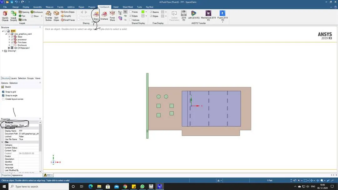
- In SpaceClaim, first, enable the topology to share, and next go to the workbench and select the share option. This enables the transfer of energy between two solid components.
BASIC MESHING:
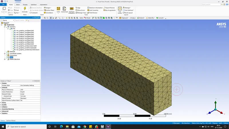
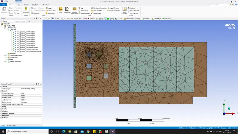
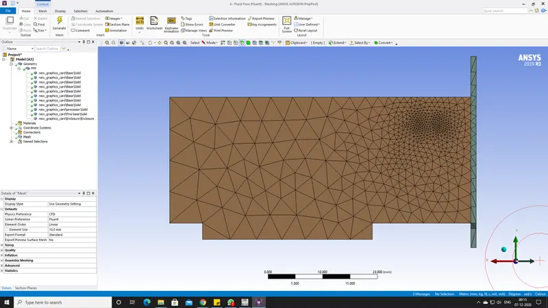
- As this is the first simulation, I have used the basic meshing properties. The element size is 10mm.
FLUENT SETTINGS:
- After opening the fluent, by following the left side tree, first, we come across the General setup. I used a steady-state solver, pressure based.
- The energy equation is enabled. We do not have multiphase operations.
- I have three solid materials and one fluid material. Material properties are as follows
| Material | Density | Heat Capacity | Thermal conductivity | |
| Aluminum (COOLING FINS) | 2719 Kg/m^3 | 871 J/Kg K | 202.4 W/mK | |
| PCB (PCB AND ELECTRONIC COMPONENTS) | 1850 Kg/m^3 | 950 J/Kg K | 0.29 W/mK | |
| Silicon (processor) | 2000 Kg/m^3 | 710 J/Kg K | 150 W/mK | (source Term) 46875000 W/M^3. |
| Air | 1.225 Kg/m^3 | 1006.43 J/Kg K | 0.0242 W/mK | (Viscosity) 1.7894e-5 Kg/m-s |
CELL ZONE CONDITIONS:
- Assign the materials to the respective components and make sure to enable the source term the enter the heat generated value here.
- This source term is responsible for showing the amount of energy dissipating from the processor or any other component we assign.
BOUNDARY CONDITIONS:
- Inlet velocity is 2 m/s and the temperature is 300K.
- The outlet is 0 gauge pressure.
- Walls have so slip conditions.
VISCOUS MODEL:
- k-Epsilon and SST model
------------------------------------------------------------------------------------------------------------------------------------------------------------------------
- After implementing the above options Initialize the hybrid simulation and check for any errors.
- Set the Temperature contour.
- Create an animation. I captured front and back frames.
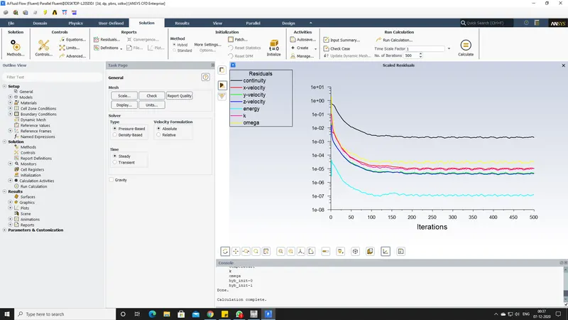
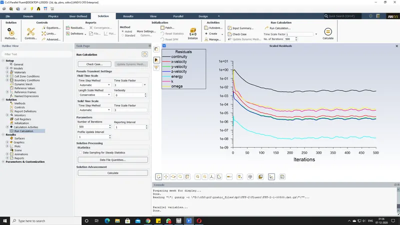
- After everything is correct, I ran the simulation for about 500 steps and the solution converged at the 110th time step.
- Below I have attached the video file and contour images.
RESULTS:
- RESIDUAL PLOTS FOR SOLUTION CONVERGENCE:
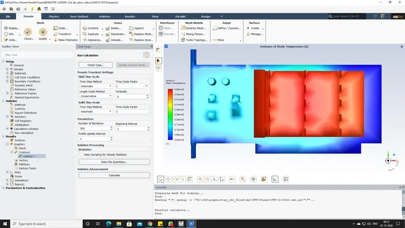
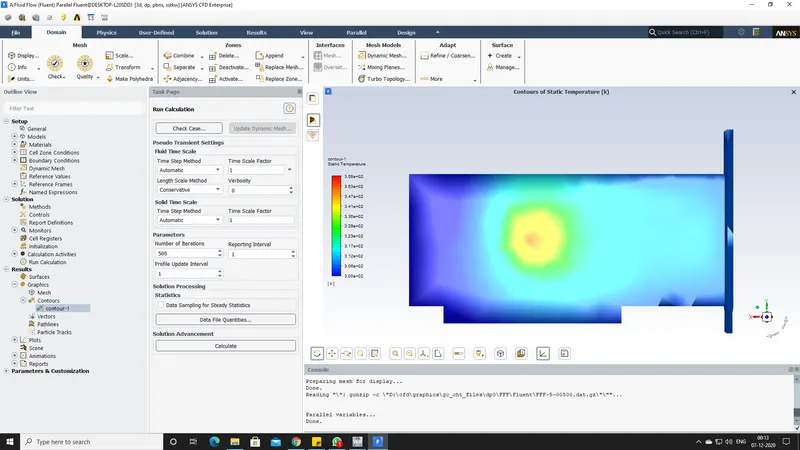
- TEMPERATURE CONTOUR
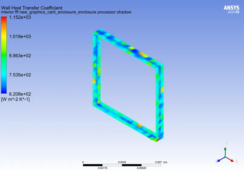
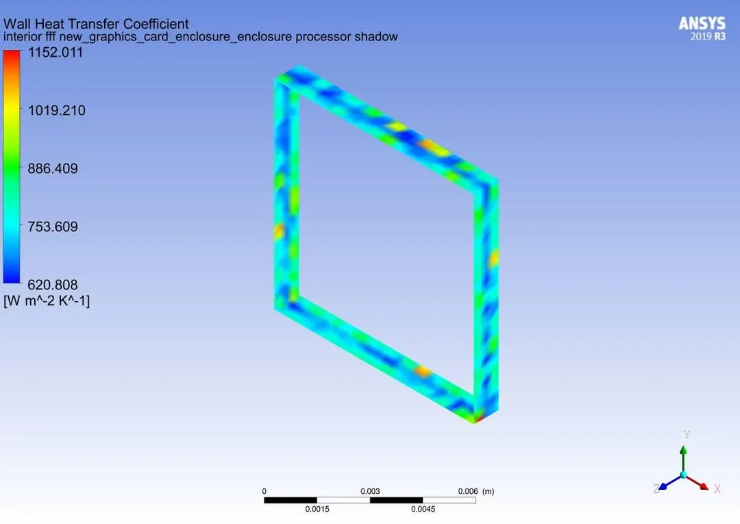
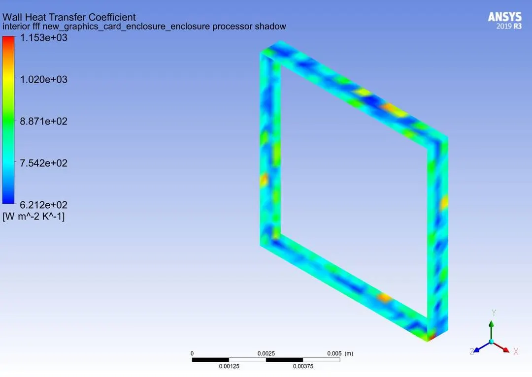
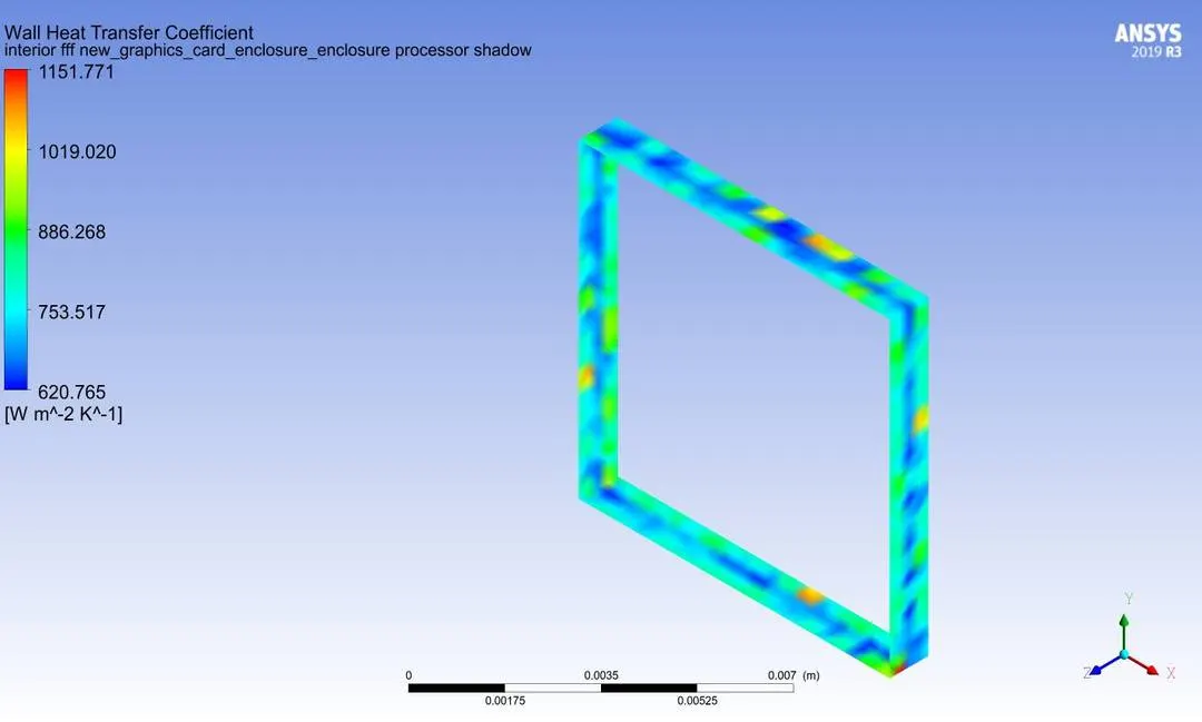
- MAXIMUM TEMPERATURE AND HEAT TRANSFER COEFFICIENT:
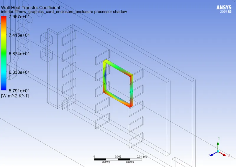
- The maximum temperature is 85-degree centigrades.
Animation:
First conclusion:
- In the above simulation, as explained before I have used a very basic mesh and the inlet velocity is 2 m/s.
- Secondly, because of the mesh element size, the simulation does not look satisfying and in the further simulations, I will refine the mesh size to maximum and change the inlet velocity and also the inlet direction.
- The solution is converged at the 150th time step.
--------------------------------------------------------------------------------------------------------------------------------------------------------------------------------------------------------------------------------------------------------------------------------------------------------
In this segment, I will be solving the problem by making the necessary changes.
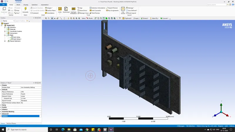
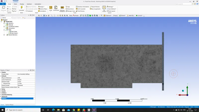
- Firstly, I will refine the mesh.
- Meshing the individual components.
- I will perform the simulation with three different inlet velocities 2, 3, and 5 m/s.
- And also I have changed the inlet velocity direction.
Meshing: Element Size = 2.5mm
FLUENT RESULTS:
- Temperature Contour with inlet velocity setting.
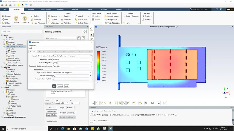
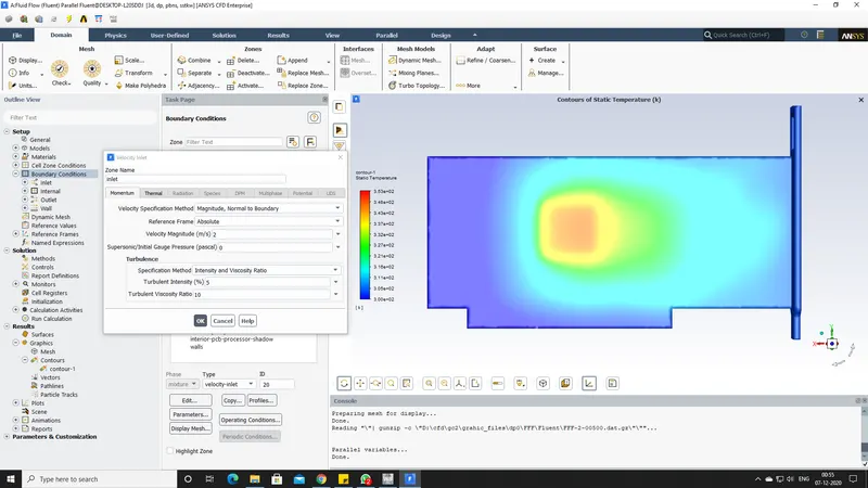
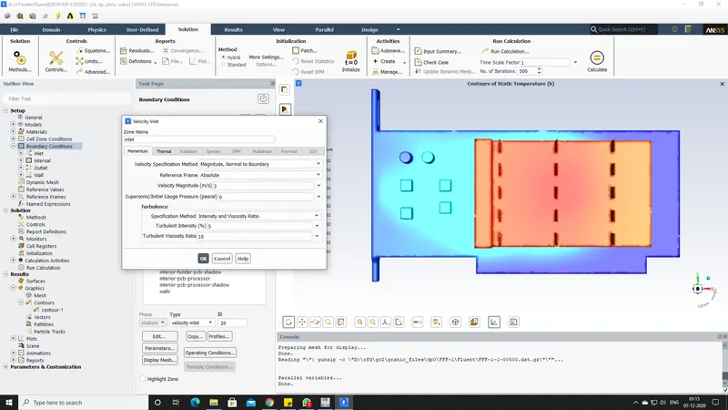
- Second simulation inlet velocity 3m/s.
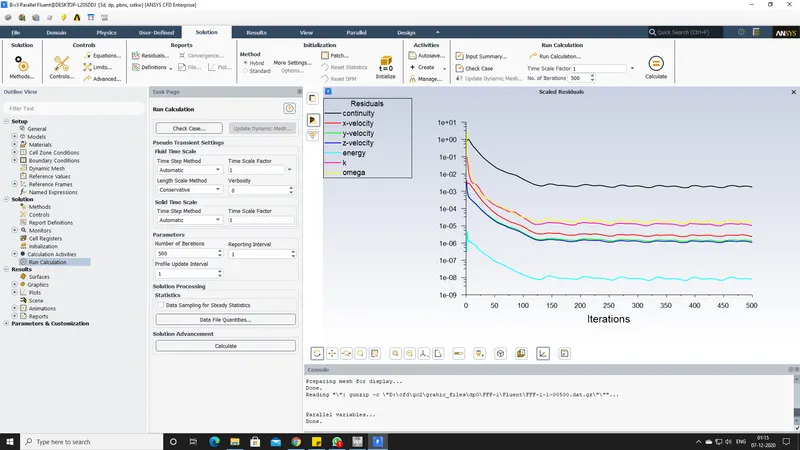
Convergence plots:
Animation:
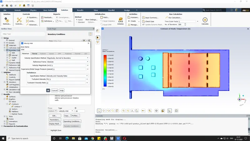
- Third simulation inlet velocity 5m/s.
Inlet velocity and temperature contour
Convergence Plots
Animation:
--------------------------------------------------------------------------------------------------------------------------------------
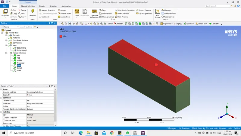
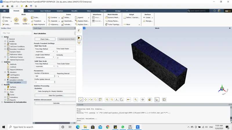
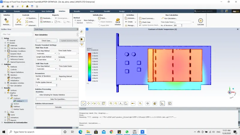
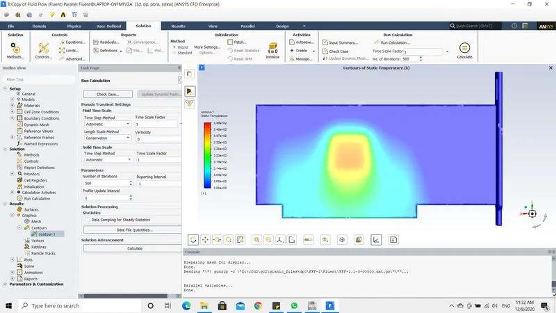
- In further steps, I have performed the same analysis on the graphics card by changing the inlet flow direction.
- Now the flow is in Y-direction. Previously the airflow was in X-Direction.
MESHING
TEMPERATURE CONTOUR:
CONCLUSION
- I would like to conclude that, I have achieved all the objectives mentioned above.
- In the first simulation, the fluid flows in X-Direction and this could cause damage to the electrical components adjacent to the fins.
- This will decrease the life of a graphics card.
- However, I am not sure about the fluid flow direction. I have changed the flow direction as mentioned shown in the last simulation.
- If we compare both the simulations, the area of heat dissipated in the first simulation is larger than the area of heat dissipated in the last simulation.
- This could reduce the component damage and increase the life span of the GPU.
- The heat can also be reduced in lesser time by increasing the number of fins and also by increasing the length of the fins.
- However, We cannot expect a higher velocity inside the cabinet. Nowadays, most of them are equipped with inbuilt fans.