Conjugate Heat Transfer Analysis on a graphics card.
CHT analysis of a graphics card
Aim:
To perform a CHT analysis of graphics cards and also understand the importance of mesh refinement and conformal mesh in a CHT study.
CHT refers to the process of heat transfer between both solids and fluids due to temperature differences and how it can be studied simultaneously. It has important applications in the design of electronic equipment, heat exchangers, automotive radiators, and the like.
Methodology:
- Run a baseline simulation and try to understand whether the results obtained follow the principles of thermal laws.
- Refine the mesh and run the case while checking for any major differences in the results.
- Run the refined mesh case for varying input velocities of 1, 2.5 & 5 m/s.
- Post-process and draw conclusions for the results obtained.
Pre-processing
The first step is to measure the required dimensions from the given CAD geometry for reference values, following which go to the workbench tab in space claim and perform the share operation. The next step is to choose the share option under the topology menu of the entire model from the design tree. This is an important step in this study as if one fails to do this the generated mesh will overlap (non-conformal mesh). We require conformal mesh for the current study.

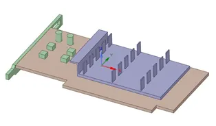
Fig: Graphics Card CAD model
Meshing
For the baseline simulation default element size of 10.18 mm was applied, while ensuring that the mesh was conformal. Whereas for the refined case, body sizing was given for fins & the base the details of the mesh are given in the table below. The mesh metrics are also shown with aid of element quality plots. The refined mesh does not show much improvement, for better-refined mesh the total number of cells amount to 0.7 – 0.8 million which computationally expensive. For the shown refined mesh body sizing was given to the three major components the base, fins & the processor.
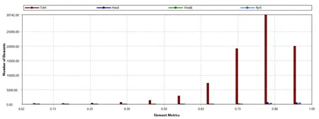
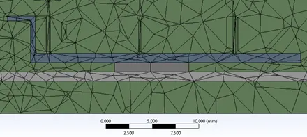
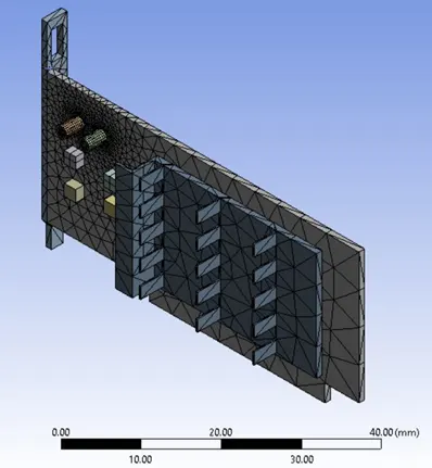
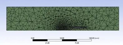
Fig: Baseline Mesh
|
Element size |
Total No of cells |
|
|
Baseline |
10.18 mm |
84121 |
|
Refined |
2 mm |
420736 |
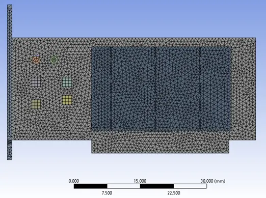
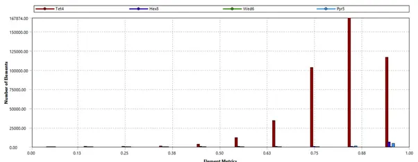
Fig: Refined Mesh
Setting up the physics
We shall be running a steady-state, pressure-based solver for solving this problem. The inlet velocity will varied as 1, 2.5 & 5 m/s. The ambient temperature is set at default value of 300 k. For giving a heat source to the processor 1watt is assumed to be the power of the heat source, for a volume of 0.008x0.008x0.001 m corresponding value is 15625000 w/m3. The heat source was applied to the processor cell zone under the source terms options. For the baseline case, inlet velocity is taken as 5m/s. The material applied here are as follows:
Base & Fins – Aluminium
Processor – Copper.
The k-ω SST turbulence model was chosen modeling turbulence.
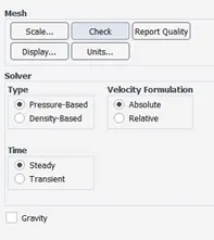
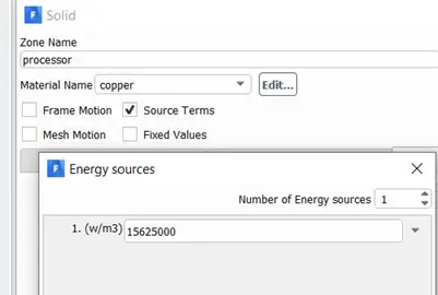
Fig: Setting up physics
Results:
Baseline Case
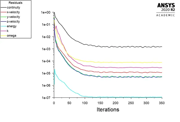
Fig: Baseline case-residuals
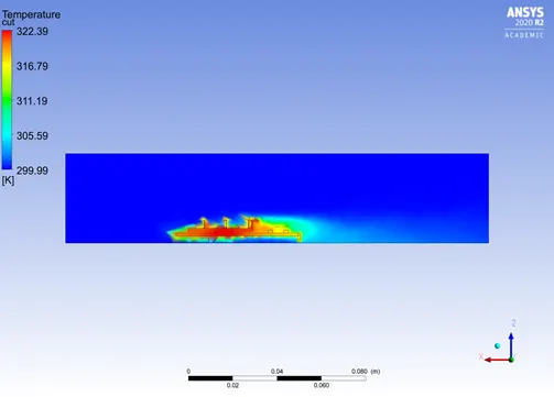
Fig: Temperature contour plot along the XZ plane
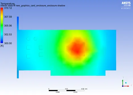
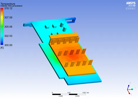
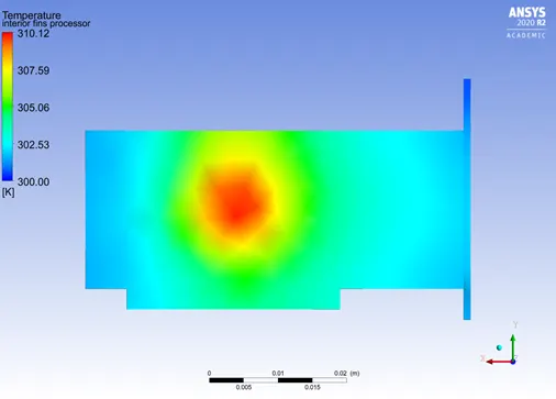
Fig: Temperature Distribution of the graphics card for baseline case.
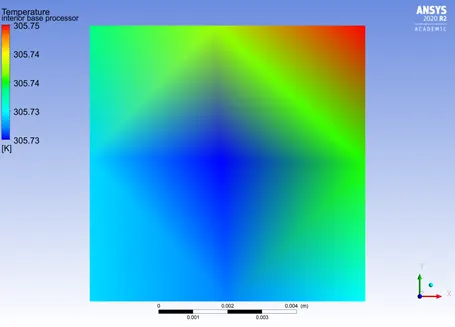
Fig: Temperature distribution of the processor for refined case (5 m/s).
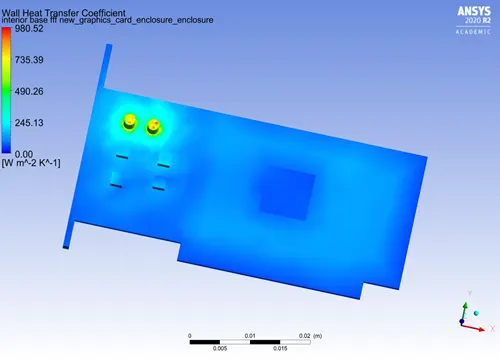
Fig: Heat transfer coefficient of the processor.
Refined Case – 5m/s
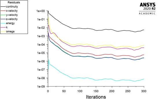
Fig: Residuals for refined case.
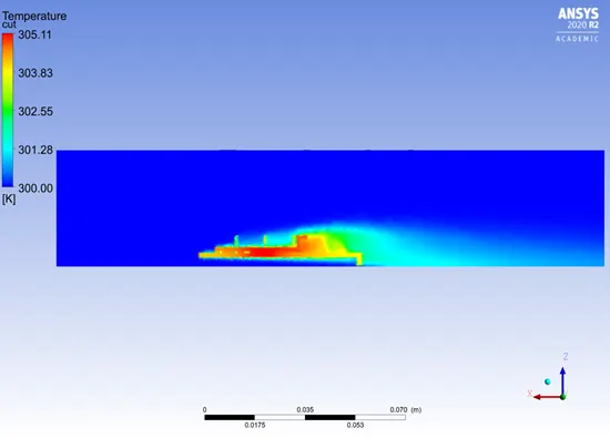
Fig: Temperature contour plot along the XZ plane
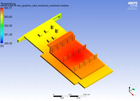
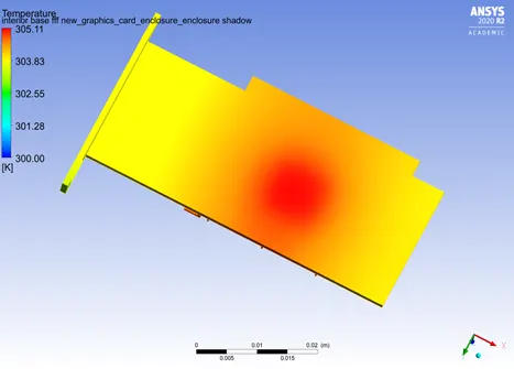
Fig: Temperature Distribution of the graphics card for refined case.
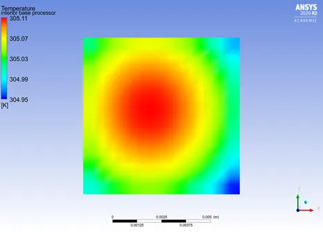
Fig: Temperature distribution of the processor for refined case (5 m/s).
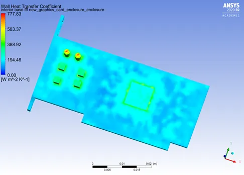
Fig: HTC of the processor.
The refined mesh is able to produce smoother contour plots an also a slight fluctuation in the temperatures of the processors can be observed. The refined mesh can be seen to provide more accurate results.
The following figures present the same plots for two velocity cases of 2.5 & 1 m/s.
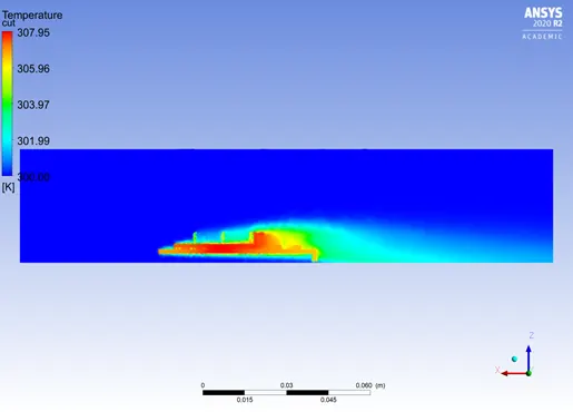
Fig: Temperature contour plot along the XZ plane-2.5m/s
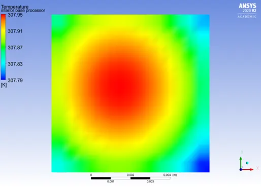
Fig: Temperature distribution of the processor for refined case (2.5 m/s).
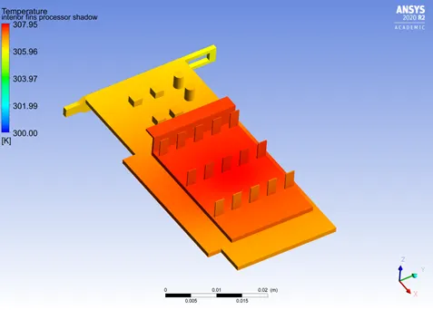
Fig: Temperature distribution for inlet velocity of 2.5 m/s.
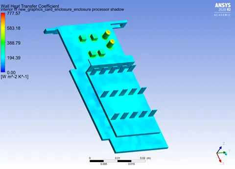
Fig: HTC for inlet velocity of 2.5 m/s.
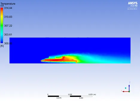
Fig: Temperature contour plot along the XZ plane-1m/s
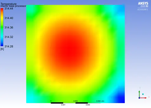
Fig: Temperature distribution of the processor for refined case (1 m/s).
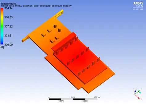
Fig: Temperature distribution for inlet velocity of 1 m/s.
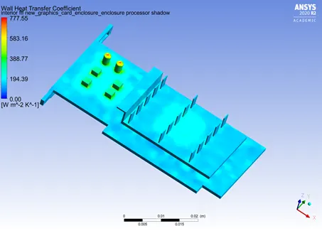
Fig: HTC for inlet velocity of 1 m/s.
Inferences & Conclusions
- Mesh quality is an important factor in the CHT study. Higher quality meshes produce better results
- The hotspot is predicted correctly by the coarse mesh.
- The maximum temperature of the processor at 5 m/s was found to be 305.75 K (Coarse mesh) & 305.11(refined mesh) and HTC values were 970 W/(m2K) Coarse & 83 W/(m2K) Refined.
- As the inlet velocity decreases the temperature of the graphics card increase as convective heat transfer reduces.