Conceptual design of a building with columns and shear walls
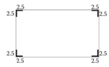
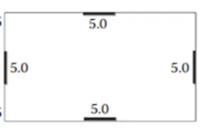
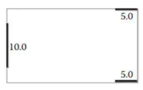
- The building shown, 20 × 35 m in plan, has columns on a 5 × 5 m grid and shear walls (with dimensions shown in m, 250 mm in thickness) in three alternative arrangements, (a), (b), (c), all with the same total cross-sectional area of the shear walls. Compare the three alternatives, taking into account the restraint of floor shrinkage, the lateral stiffness and the torsional one with respect to the vertical axis, the vertical reinforcement required for the same total flexural capacity at the base, the static eccentricity, the system’s redundancy, foundation systems, architectural constraints etc.
|
Criteria |
 |
 |
 |
|
Restraint of Floor shrinkage |
In this case, since the shear walls are placed at the corners, the floor is restrained at all four corners. As a result of that the floor will experience higher shrinkage and lead to shrinkage cracks. |
The shear walls are placed along the mid-edges in all four sides but the corners are left free. In this case the floor does not experience much shrinkage so less cracks will develop compared to option 1 |
In this case, the shear walls placed non-uniformly. The floor is restrained in left short edge but right edge left free and restrained at top and bottom at right side only. So, floor is not effectively restrained and result in less cracks. |
|
Lateral Stiffness |
The shear walls are placed at the corners of the floor, the edges of the floor do not have any support. If the building experience any lateral force tends to act along the edges of the floor, this placement of shear walls will have least stiffness in both directions. |
The shear walls are placed along the edges of the structure. This option has more stability and the lateral stiffness will also be more along both the directions. |
Along X direction the shear wall is provided at left side only and in Y direction the shear walls are provided at right side. As the shear walls are non-uniformly provided this option has least stiffness in both direction. |
|
Torsion with vertical axis |
The placement of shear walls are symmetric, hence there is no eccentricity between the center of mass and center of stiffness, both coincides. So, the corner shear walls provide more resistance to Torsion. |
In this option also placement of shear walls are symmetric, hence there is no eccentricity between the center of mass and center of stiffness, both coincides. So less prone to Torsion. |
In this option shear walls are placed unsymmetrically along the y direction. So, the center of stiffness shifts towards the left edge and as such there is an eccentricity between the center of mass and center of stiffness which leads to torsional instability. |
|
Vertical rebar at Base |
The shear walls in corner are subjected to nominal flexural moment and heavy twisting moment. So, amount of reinforcement required will be more. |
The shear walls in the edge are subjected to nominal twisting moment and subjected to heavy lateral force. So. amount of reinforcement required will be more. |
The shear walls are placed unsymmetrically along the y direction. The walls are subjected to heavy flexural and twisting moments. So, the amount of reinforcement required will be more compared to other two options. |
|
Static eccentricity |
The shear walls are symmetrically placed at the corners, the center of mass and center of stiffness coincides and there is no eccentricity. |
The shear walls are symmetrically placed along the edges, the center of mass and center of stiffness coincides and there is no eccentricity. |
The shear walls are placed symmetrical along X direction only. But in the Y direction there is only one shear wall along the left edge with a heavier mass compared to other two shear walls. Due to this, the center of stiffness shifts to the left. So, this option has eccentricity. |
|
System’s redundancy |
The shear walls are placed uniformly at the corners and shear walls are symmetrical on both the direction. This option has good redundancy. |
The shear walls are symmetrically placed along the edges. So, this option also has good redundancy. |
In this option shear walls are placed symmetrical along X direction only and also there is concentration of load at the left edge, this arrangement is not redundant. It has poor redundancy. |
|
Foundation system |
In this option L shapes shear walls are provided, the geometry and design of the foundation will be critical. |
The shear walls are provided along the edge which are in line and symmetric. It is easy to design and fix the geometry of the foundation. |
The shear walls are in line it will be easy to fix the geometry but due to concentrated loads the design of foundation will be critical. |
|
Architectural constraints |
This option is architecturally very effective, since shear walls obstruct only at corners. |
Architecturally may not be recommended since all four faces in the middle were obstructed. This shear wall arrangement may disturb open space requirement. |
Left side is completely restricted due to Prescence of long shear wall. All other sides are okay with respect to architectural point of view. |
- Discuss the suitability for earthquake resistance of the moment resisting framing plan of a three-storey building depicted here (cross-sectional dimensions in cm), the eccentricity of the centre of mass (as centroid of floor plan) to the centre of stiffness (from the moments of inertia of the columns) are shown. Suggest an alternative. Also, is there torsional flexibility? Are the two fundamental translational modes of vibration larger than the fundamental torsional mode of vibration. Discuss qualitatively.
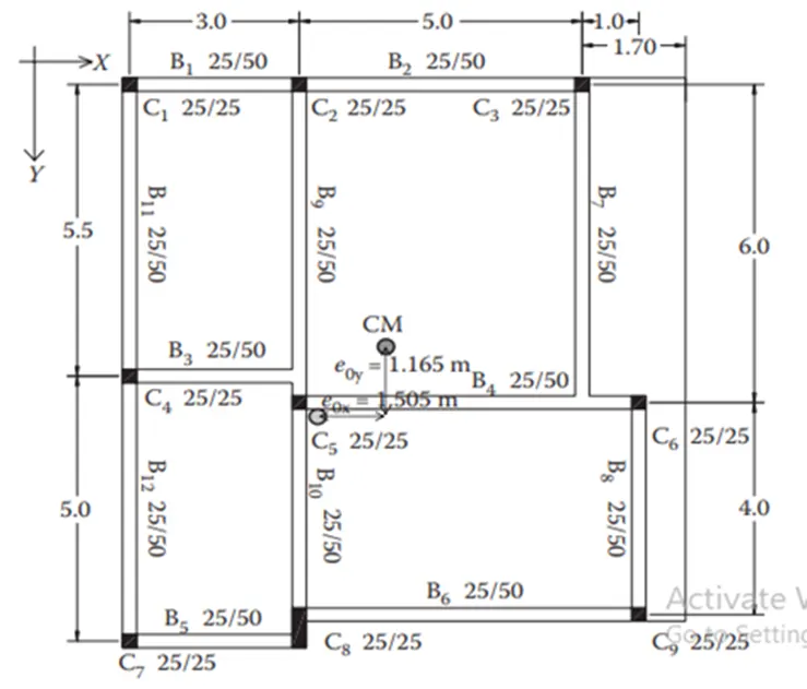
Indirect lateral load transfer in X and Y direction
From the given plan observation, we can find that some of the beams which not directly connected to beam-column junction, they we connected to other beams so they act as secondary beams. In these cases, there will be a heavy shear force acting on the primary beams due to the secondary beams such that the primary beams are prone to the shear failures. The alternative for this condition is to keep all the beams in a straight line such that all the axes of the beams should pass in a line.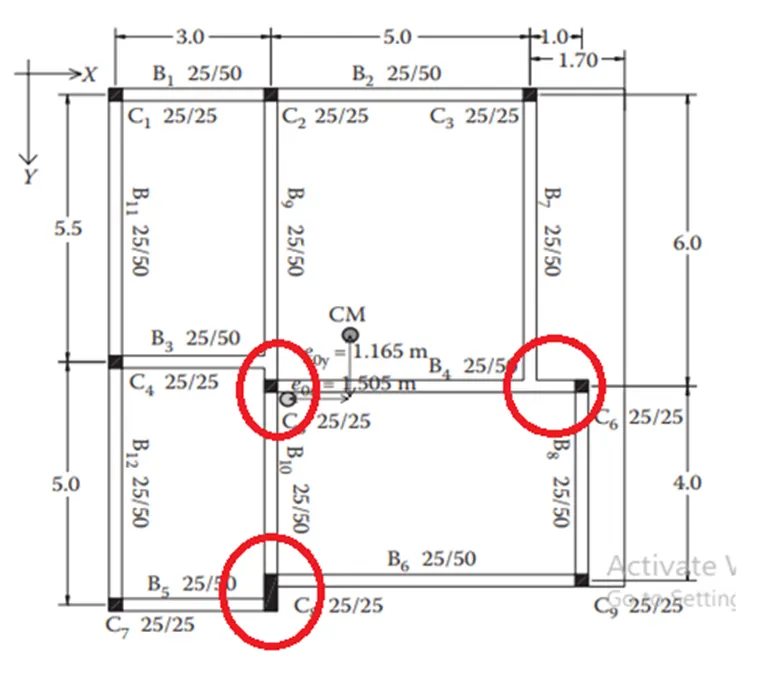
Eccentricity
As provided in the above image, the center of mass of the is not matching with the center of the stiffness of the building, so due to this some eccentricity gets developed leading to the torsional moment in the structure. To reduce the eccentricity of this plan is done by some modifications in Plan. This can be done by make the structure more symmetrical in the geometry of the beams and columns provided.
Strong beam weak column
In the given plan the dimensions of beams and columns were provided. We can clearly observe that the cross section i.e., depth of beam is of bigger size than that of the column, so we can understand that the beams present are stronger than the columns available in the building. The size of columns majorly mentioned as 25 cm x 25 cm. But all the beams have much deeper section (50cm). Inertia of beam is visually higher than column. If the column reinforcement is adequately greater than that of beams, we are okay and since we do not have the reinforcement detail, this is doubtful. It is recommended to have slight bigger sizes for column. This could lead to the strong beam-weak column mechanism. To make the columns stronger than beams to adequate reinforcement is provide for columns.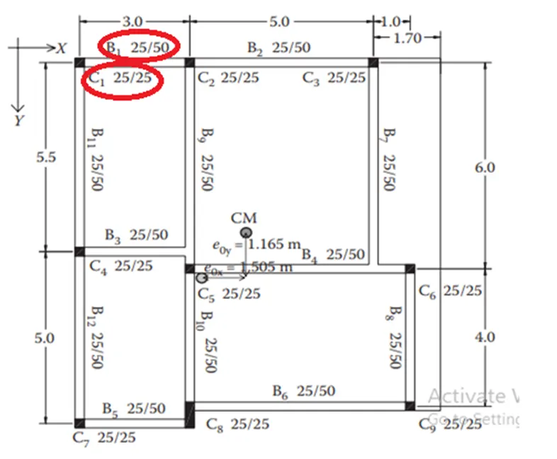
Alternative plan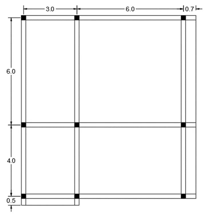
- A multi-storey building with basement, with a quadrilateral(non symmetrical floor plan) plan as, has interior columns in an irregular (not in a grid) pattern in plan that serves architectural and functional considerations. Partition walls and interior beams supporting the slab have different layout in different stories. However, there is no constraint to the type, location and size of the lateral force resisting components and sub-systems on the perimeter. Proposals are to be made and justified for the choice of the lateral-load-resisting system and its foundation.
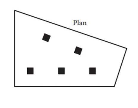
Floor Plan
The given floor plan is not symmetrical in both the direction and it not uniform also. As the plan is irregular in nature as a result if any lateral load induced on the floor will not have the 100% influence in the same direction, so definitely a special lateral load resisting system for these torsional moments should be accommodated.
Internal Columns
The internal columns present in the building are not in symmetry. And they are arranged parallel to the edge of the site. 3 columns are in one axis which are along X direction while the remaining 2 columns are in another axis. So due to their random appearance of the columns in the floor plan they may not take lateral load efficiently, where the primary purpose of the columns is just to carry gravity load alone of the building.
Floor to floor variation of Internal walls and beams
As the information provided about the building it is mentioned that the internal wall system will differ from the floor to floor. As the internal walls do provide as an important mass of the entire structure, it plays a key role in shear transfer from floor to slab to beam, where this will be proper when the elements are in order but in this case the elements are not in proper order which will lead to heavy distortion.
Suggestion on lateral load and its foundation
- From the observation of plan, we know that heavy torsional moments may generate due to seismic forces. So that that the structural members have to resist the lateral load. To facilitate the building with good lateral stiffness shear walls are suggested at the corners.
- The floor is having greater area on the left side when compared to the right part, so the corner walls to be provided should be heavy on the left side such as to take the heavy shear present on the left side due to less cross-sectional area.
- As it was decided to provide the corner shear walls, the box type foundation will be suitable for the respective corner shear walls. And here the corner shear walls only be suitable as to resist the torsional moments generated in the structure and even under the architectural point of view they will be suitable.
- The internal columns can be provided with the isolated footings where ultimately these isolated footings have to be connected to the shear walls with the tie beams.