Conceptual design of a building with columns and shear walls
Question 1: The building shown, 20 × 35 m in the plan, has columns on a 5 × 5 m grid and shear walls (with dimensions shown in m, 250 mm in thickness) in three alternative arrangements, (a), (b), (c), all with the same total cross-sectional area of the shear walls. Compare the three alternatives, taking into account the restraint of floor shrinkage, the lateral stiffness, and the torsional one concerning the vertical axis, the vertical reinforcement required for the same total flexural capacity at the base, the static eccentricity, the system’s redundancy, foundation systems, architectural constraints, etc.
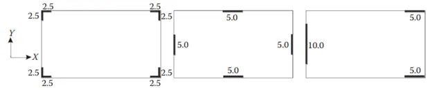
AIM:- To compare the three alternatives and identify suitable ones for the criteria.
Procedure:-
Criteria:-
- Restraint of floor shrinkage
- The lateral stiffness
- The torsional one with respect to the vertical axis
- The vertical reinforcement required for the same total flexural capacity at the base
- The static eccentricity
- The system’s redundancy
- Foundation systems
- Architectural constraints
Plans:-
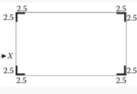 Option-a
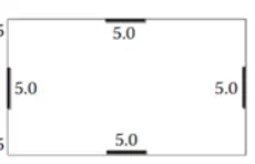 Option-b
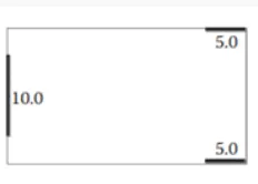 Option-c
1). Restraint of floor shrinkage, the lateral stiffness:-
Option-a): As we can see at the four edges shear walls are present which does not allow them to the floor will shrinkage. This results in floor tension will be developed against shear walls and shrinkage phenomena thus it leads to developed cracks in the floor.
Option-b): As we can see the four shear walls are present at the mide of four sides which results in it will less restraint capacity to resist floor shrinkage because at the edge the floor will shrinkage as a result cracks will be developed but less or minor as compared to option-a.
Option-c): As we can see the non-uniform arrangement are visible two end edges are restrained and only one left wall are restrained a shrinkage point of view the cracks are not developed or possibly less because if the floor will shrink it will be maximum and uniform opening are available (as shown in figure 1.1) it will shrinkage that portion.
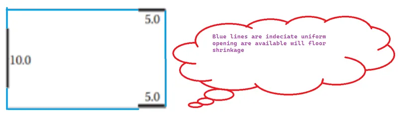 Figure.no- 1.1
Conclusion:-
As we compare options a,b, and c.
- Restrain in floor shrinkage (a>b>c)
- Cracks developed (a>b>c)
2). The lateral stiffness:-
Option-a): As we can see the shear walls are presented at the corner of the side and in mide large portion is free it also has the horizontal seismic excitation path(along the edge) which has the least stability and hence the lateral stiffness will be less along both X-Y direction.
Option-b): As we can see the shear wall are placed uniformly and along the seismic excitation path which is more stable and provides higher lateral stiffness in both X and Y directions.
Option-c): As we can see the shear wall is not placed uniformly and it is also not along the seismic excitation path which is very unstable and structural and also provided very less lateral stiffness in both X-Y directions.
Conclusion:-
As we compare to Option a,b, and c.
b-option is more stable and it provides higher lateral stiffness as compared to options a and c (b>a>c).
b will provide higher lateral stiffness for a pure seismic acceleration in the X and Y direction.
3). The torsional one with respect to the vertical axis:-
Option-a): Option-a will provide more resistance to twist because its placement is symmetric and the center of mass and center of stiffness along the vertical direction coincides with each other. So it will be difficult to twist the floor in a vertical direction.
Option-b): In option-b will provide good resistance to twist because its placement is symmetric and the center of mass and center of stiffness along the vertical direction also coincide with each other. But if we compare option-a and option-b "a" is more resistant as compared to option-b because we see the table they are more stable and strong when we placed their legs at the edge of the table but the same table acts less stable and strong when we placed their legs at the center of sides.
Option-c): As we can see the wall placed are irregular the symmetric is not good and the center of the mass center of stiffness and eccentricity is also not coinciding with each other. Hence it will provide very poor resistance to twist as compared to option-a and option-b.
Conclusion:-
As we compare to options a,b, and c.
Option-a is very good in torsion with respect to a vertical axis as compared to a,b, and c. Resistant to twist (a>b>c).
4.) The vertical reinforcement required for the same total flexural capacity at the base.
Option-a): As we can see at the edges of sides which provide nominal flexural moment and a heavy twisting moment or it does not have any eccentricity or it does not take high resistance against lateral force. so because of the heavy twisting moment, it required some vertical reinforcement.
Option-b): As we see the walls are placed at the center of the sides which gives the least flexural moment and nominal twisting moment. so it helps to resist the lateral forces and provide greater strength hence option-b will not much required vertical reinforcement or less required as compared to option-a.
Option-c): As we see the walls that are not placed will be symmetric and will have eccentricity which gives a large amount of flexural moment and high twisting moment as this will not resist lateral force hence it will require more vertical reinforcement as compared to other options.
Conclusion:-
As we compare to options a,b, and c.
The option-b is the least requirement of vertical reinforcement and c is the highest required vertical.
Required vertical reinforcement (c>a>b).
5.) The static eccentricity.
Option-a): Previously we conclude that option-a will not have any eccentricity because of the placement of shear walls and it is structural symmetricity.
Option-b): As we see option-b is also will symmetric and it will not have any eccentricity because of its shear wall placement and its structural symmetric.
Option-c): As we see previously in option-c we found eccentricity because of the un-symmetric placement of shear walls.
Conclusion:-
As we compare options a,b, and c.
c-option will have static eccentricity and it is significant.
6.) The static eccentricity:-
Option-a): We can see the placement of the wall is symmetric and uniformly placed in both X and Y directions. so it also resists lateral load in both direct properly so we can say the system or option is redundant.
Option-b): We can see the placement of the wall is symmetric and uniformly placed in both X and Y directions. which means shear walls are carried equal and distributed lateral load in X and Y directions. So we conclude that the system or option "b" is redundant.
Option-c): We can see that in option "c" the placement is walls is unsymmetric and concentrated lateral load support in both directions. In X-direction only the left side wall is placed and the right side is completely open. and Y-direction 3 and 4th Quardent are open hence the system and option "c" is not redundant.
Conclusion:-
As we compare options a,b, and c.
a and b options are redundant but the option is less redundant (b>a>c).
7.) Foundation systems:-
Option-a): As we observe that shear walls look like L-shaped walls so as we know L, T, U, and H shape walls have high stiffness and strength in both horizontal directions. the geometry of the foundation and its design will be critical because of the building footprint area and comprising a wall around the perimeter pulse of two rigid horizontal diaphragms.
Option-b): As we see the wall are in line and easy to fix with the geometry and design of the foundation.
Option-c): As we see the placement of the wall is along of sides and concentrates. so it will make it easy to fix the foundation but it symmetric will make design critical.
Conclusion:- As we compare options a,b, and c.
Options b and c shall be incorporated with isolated footing and strip footing.
Option-a will provide a peripheral box foundation.
8.) Architectural constraints:-
Option-a): As we see walls are placed at the corners which will not clash between structure and architecture.
Option-b): As we see walls are placed in the middle of the sides which makes the clash between structural and architectural.
Option-c): As we see walls are unsymmetric and concentrated which will not be preferable for both structural and Architectural.
Conclusion:-
In option-a is the preferred one. Option-b is subject to discussion and option-c is not accepted both structural and architectural.
Question 2: Discuss the suitability for earthquake resistance of the moment-resisting framing plan of a three-story building depicted here (cross-sectional dimensions in cm), the eccentricity of the center of mass (as the centroid of floor plan) to the center of stiffness (from the moments of inertia of the columns) are shown. Suggest an alternative. Also, is there torsional flexibility? Are the two fundamental translational modes of vibration larger than the fundamental torsional mode of vibration? Discuss qualitatively.
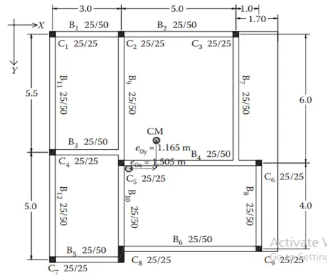
AIM:- To determine the suitability for earthquake resistance of the moment resisting framing plan for a given Building.
Procedure:-
Observations:
- In direct lateral load transfer in X and Y direction.
- Eccentricity X and Y direction torsional.
- Strong beam weak column possibility.
i): As we see in the plan the lateral load does not transfer uniformly/directly from one end to another in both X and Y directions (Circles 1, 2, and 3) shown in the figure.no 2.1. In this way, the beam and column will face shear failure. If we explain the connection the beam will connect to another beam and the beam is not continuous along the direction.
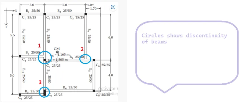 Figure-no:2.1
ii). As we see in the plan eccentricity is mentioned at the distance of (1.505,1.165m) from the center of mass which means the center of mass and center of stiffness is not in the same position as a result of a higher torsional moment of the building will appear in both X and Y direction.
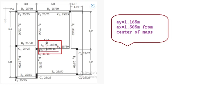 Figure.no-2.2
iii). As we see in the plan the beam size is bigger than the columns is possible the weak beam and strong column mechanism will not be followed here, as a result, the seismic force will appear building will collapse completely without any warning.
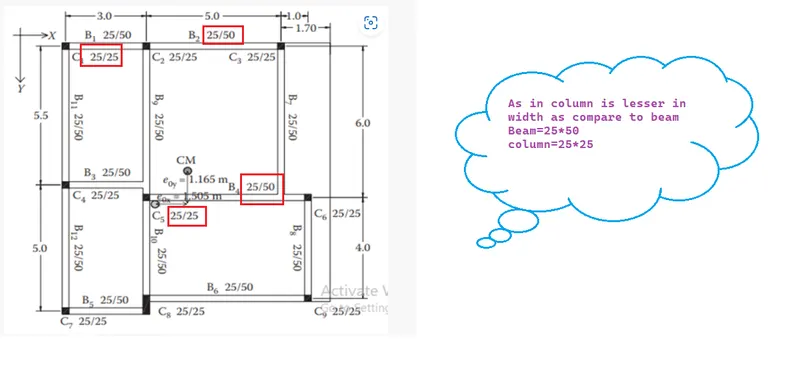 Figure.no-2.3
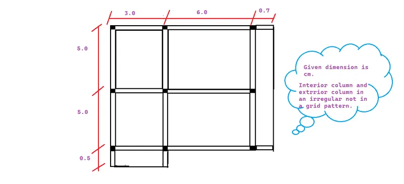 Figure.no-2.4
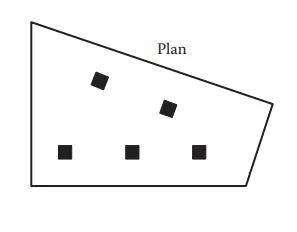
Question 3: A multi-story building with a basement, with a quadrilateral (non-symmetrical floor plan) plan as, has interior columns in an irregular (not in a grid) pattern in a plan that serves architectural and functional considerations. Partition walls and interior beams supporting the slab have a different layout in different stories. However, there is no constraint to the type, location, and size of the lateral force-resisting components and sub-systems on the perimeter. Proposals are to be made and justified for the choice of the lateral-load-resisting system and its foundation.
AIM:- Observation of the given plan and identify what is wrong and recommended it.
Procedure:-
i). Floor Plan- As we see the floor plan area is not in uniform or un-symmetric, as a result, any lateral load will not transfer 100% in the same direction hence torsional moment will be generated.
ii). Random Internal column- As in the plan the random internal columns are placed as a result diversity in the load transfer will occur and unable to transfer load efficiently (possibly not get achieve the required strength of the building). so we assume and design those columns for only gravity loads.
iii) As in the plan center of mass and the center of stiffness is not in the same place as a result structure will carry eccentricity hence torsional moment will appear.
iv). Floor-to-floor variations in partition walls and beams- As in the question, it will mention non-symmetrical floor plan or quadrilateral shape plan in that way partition walls provide an important role in mass distribution in a beam provide an important role in mass distribution in a beam and columns to transfer the lateral load uniformly or smoothly. so these members are not considered properly. so heavy distortion and distribution of lateral loads will happen.
Suggestion:-
- As we see the building will face heavy torsional moments so we try to control with help of lateral load by implementing the heavy shear wall along the edges of the sides and those shear walls connect with the beam to provide smooth load transfer.
- We provide a shear wall at the edge the shape of the wall should be L- shape so the type of shape wall we provide prefers all box foundations.
- The internal columns shall be supported by isolated footing and connected with a shear wall through a tie beam.
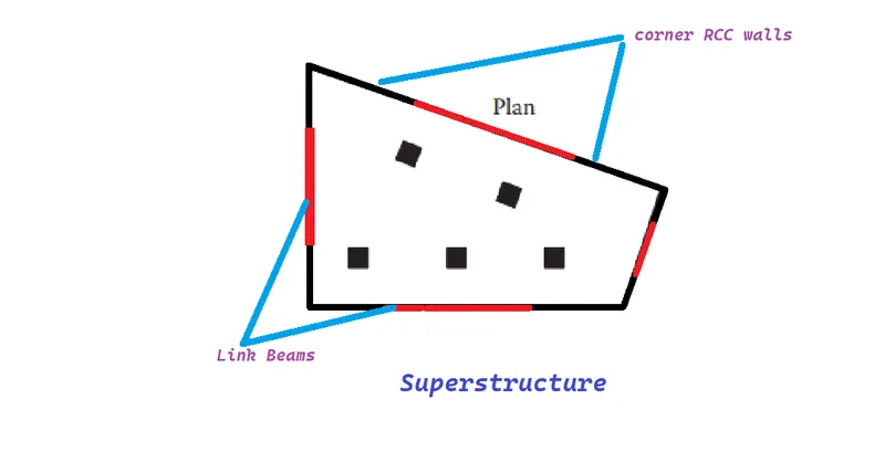 Figure.no-3.1
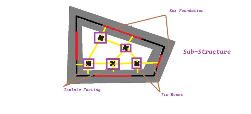 Figure.no-3.2