Concept on positioning of Columns
Question 1: Comment on the layout of the framing plan concerning earthquake resistance in the two horizontal directions X or Y (dots are columns, and lines depict beams). Look into aspects of symmetry, redundancy, and bi-directional stiffness and ductility.
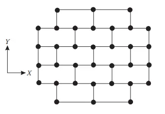
Figure No. 1.1
AIM:- To determine the layout of the framing plan concerning earthquake resistance in given aspects for a given figure.
Introduction:-
- Symmetry:-Symmetry is defined as a balanced and proportionate similarity that is found in two halves of an object.
- Redundancy:- Redundancy is defined as redundancy that exists as a result of the continuity within the load path.A sufficient no of supports and arrangements specified manner and proper space between them
- Bi-directional Stiffness:- Stiffness is defined as the resistance to a force causing a member to bend.
- Ductility:- Ductility describes the extent to which a material (or structure) can undergo large deformations without failing.
Procedure:-
A). Symmetry:
i). Symmetry in the X-direction:-
If we have drawn a line in the middle portion or split in half of the plane perpendicular to the X-axis we see the plan look like the mirror each other we conclude that the given plan is Symmetric in the X-direction.
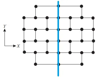 Figure No. 1.2
ii). Symmetry in the Y-direction:-
Same as we drew a line in the middle portion of the plane perpendicular to the Y-axis or split in half along the X-direction we see the plan look like the mirror of each other so we conclude that the given plan is symmetric along the Y-direction also.
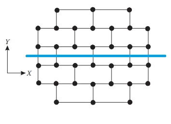 Figure No. 1.3
B). Redundancy:
i). Redundancy in the X-direction:-
In the plan, we see the no of columns in the X-direction is 7 and the top-bottom rows are having 3 no columns. and these columns are evenly spaced .so the structure is more redundant in the X-direction.
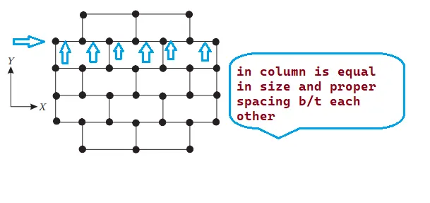 Figure No. 1.4
i). Redundancy in the X-direction:-
In the plan, we see the no of the columns in Y-direction is a maximum of 6 and a minimum is 4 and they are evenly spaced so the structure is redundant in Y-direction
The mass of each column in the X-direction is greater than the mass of each column in the Y-direction so the Y-direction is redundant but lesser than the X-direction.
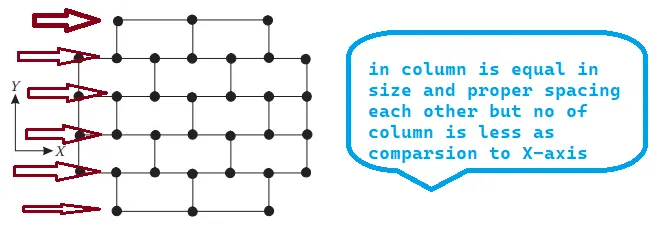 Figure No. 1.5
C). Bi-Directional Stiffness:-
i). Bi-directional stiffness along X-direction:-
In the plan, we see the column in the X-direction is connected to the beam in a straight line in a continuous manner.
So that any load that comes to the left end towards in +ve X-direction the load will transfer easily to the right end So, less possibility of force diversion takes place with seismic force in X-direction. The framing plan is strong concerning bi-directional stiffness in the X-direction.
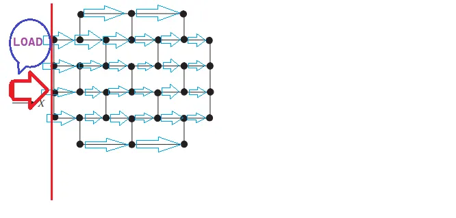 Figure No. 1.6
ii). Bi-directional stiffness along Y-direction:-
If we see the plan the arrangement column and beam in Y-direction are connected but not in a continuous manner. so that if any load comes in bottom towards the top the force are get diverted to +_ve X-direction. there will be major forces diversion take place with seismic force in Y-direction. The framing plan is weak concerning bi-direction stiffness in Y-direction.
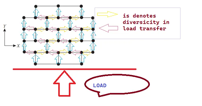 Figure No. 1.7
D). Ductility:-
i). Ductility along X-direction:-
As we know ductility is inversely proportional to stiffness so as we know in the X-direction stiffness is high (previously identify) hence it will result in higher stiffness of the building in the X-direction which would reduce ductility in the X-axis or we say in X-direction ductility is less as compare to Y-axis.
ii). Ductility along Y-direction:-
We know that in the y-direction stiffness is less(previously identify) as compared to X-direction because of the discontinuous connection of the beam hence it will result in lesser stiffness of the building in the Y-direction, which would be more ductile in the Y-axis or we say in Y-direction ductility is more as compare to X-direction.
RESULT:-
Question 2: What are the possible sources of irregularity in the building shown here? Explain how, as an engineer, each of these irregularities should be dealt with.
 Figure No. 2.1
AIM:- To identify the irregularity in the given building and explain how these irregularities should be dealt with.
Introduction:- In the given building, there are three irregularities visible.
- Vertical irregularity
- Soft Storey
- Sloppy Base
Procedure:-
1. Vertical Irregularity:- we see the bottom area is greater as compared to the upper area of the building as per IS1893-2016 Table 6 serial(iii)
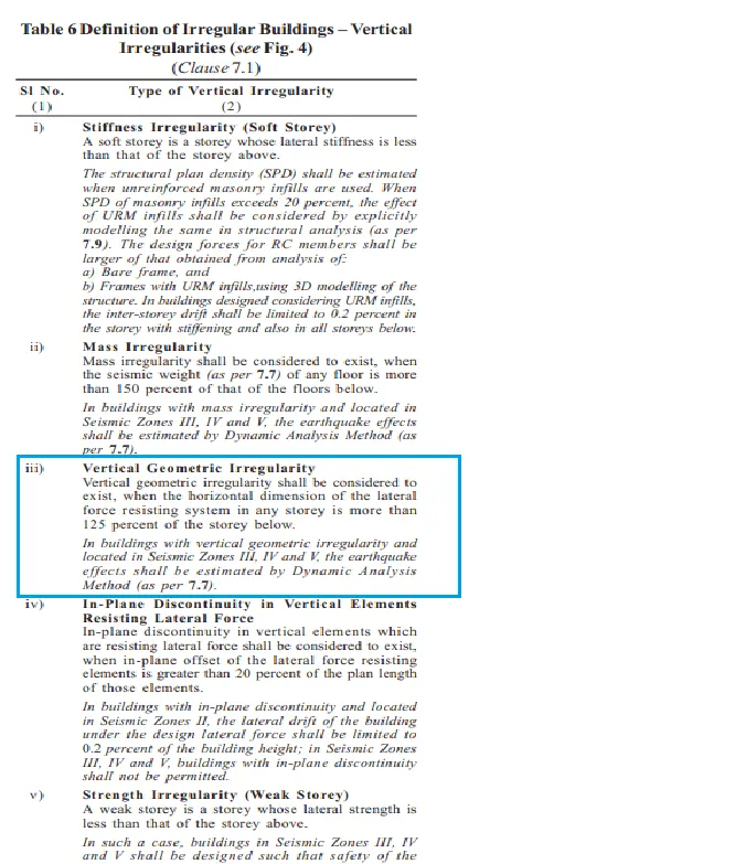 Figure No. 2.2
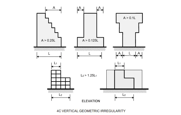 Figure No. 2.3
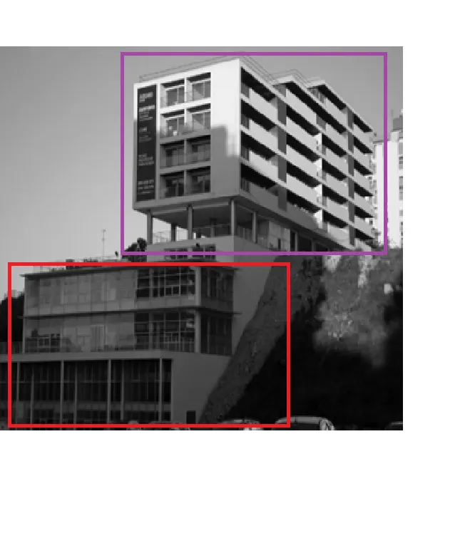 Figure No. 2.4
2. Soft story:- As we see in the middle portion of the building the sixth floor is constructed by only columns, not occupancy or no shear wall/ partition wall. As we know that this will leads to plastic hinge formation at the columns. This is also known as stiffness irregularity. As per IS 1893-2016 Table 6 serial(i)
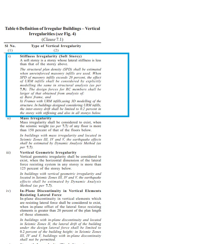 Figure No. 2.5
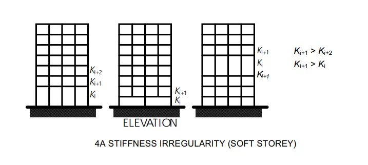 Figure No. 2.6
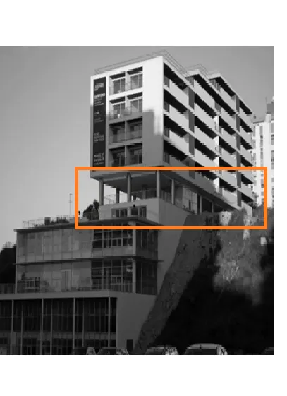 Figure No. 2.7
3. Sloppy Base:- In a given building the sides of the building are sloppy building is constructed on the sloppy ground at one side. so it will lead to variation in the stiffness or may be possible to collapse during the earthquake. So, if we constructed according to IS 1893-2016 code. We possibility to protect the building during an earthquake. IS 1893-2016 FIG 5E
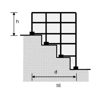 Figure No. 2.8
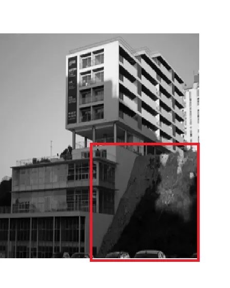 Figure No. 2.9
RESULT:-
Question 3: A 4-story hotel building has an open ground floor for the restaurant. Story 2 to 4 has one row of rooms along each long side in the plan, separated by a corridor. The two short sides of the perimeter are fully in-filled in all stories, except for certain openings at the ends of the corridor at stories 2 to 4 and along the right-hand side of the ground floor. There is a staircase near the upper left-hand corner, with straight flights between landings at floor levels and in-between floors. Cross-section dimensions are written next to the member no. in meters.
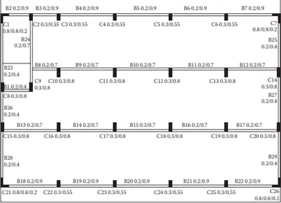 Figure No. 3.1
Comment on the features of the structural design and of the layout of infills which are important for earthquake resistance and seismic performance. How do they relate to the almost full collapse of this building (the extreme left-hand bay with the staircase survived, as well as one long-side façade in the rear end, and the frame along the right-hand side in plan)?
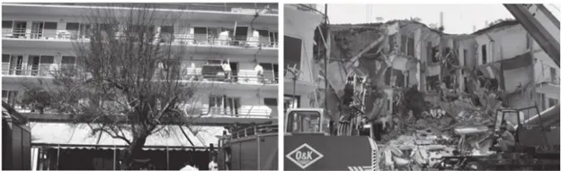 Figure No. 3.2
AIM:- Comment on the features of the structural design of the given building.
Introduction:- In the given building there are 7 irregularities and errors in structural design.
- Open Ground Floor(Soft Story)
- Rooms along two bays separated by an open corridor(mass irregularity)
- Two short sides covered with infill walls(Stiffness irregularity)
- Staircase position at left top corner
- No framing connection along Y-direction(diversity in transferring load)
- Beams connected along column minor axes(ductility irregularity along Y-axis is less)
- Variations in column sizes
Procedure:-
1). Open Ground Floor:-
As it mentions an open ground floor, means that the ground acts as a soft story of the building causing damage to the building in earthquakes appear(AS PER IS 1893-2016 Table 6 Serial (i))
 Figure No. 3.3
Figure No. 3.4
Figure No. 3.5
2). Rooms along two bays separated by an open corridor:-
As we see the building is divided into three parts on the basis of mass. It is also known as mass irregularity. These two left and right rooms have a higher mass density as compared to the middle corridor (it will very less as compared to the side of the room)
 Figure No. 3.6
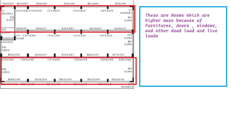 Figure No. 3.7
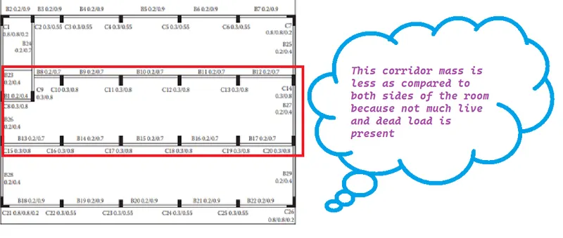 Figure No. 3.8
3). Two short sides covered with infill walls:-
As we see that short side is not filled in the story, except 2 to 4 and along the right-hand side only, which means that the in-filled makes a stiffer difference between these floors and the side.
This means the building left and right sides periphery is stiffer during seismic forces special along north-south
Hence we can say when an earthquake comes the load to resist is different and its chance to maybe collapse or it will make damage the building
 Figure No. 3.9
4). Staircase position at left top corner:-
As we can see the staircase portion is not affected during earthquakes because usually the staircase and lift portion are stiffer than other members of the building.
It means it does not damage or collapse easily with high seism force appeared. As we can see the building's only staircase part is not damaged because it is stiffer than other
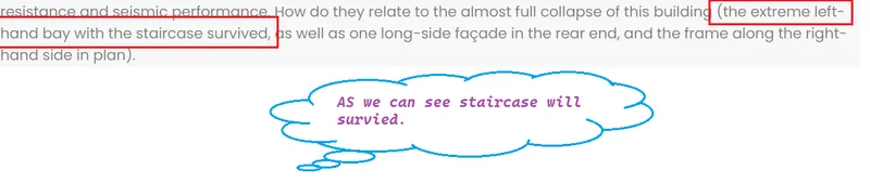 Figure No. 3.10
5). No framing connection along Y-direction:-
As we see they are only the last long left or right beam connected to Y-axis in the middle portion, not any single beam connected along Y-axis.
This means the building is more vulnerable during the earthquake because of no Y-axis beams are connected reason is that if the load has come in Y-direction it will be difficult to transfer the load from the -ve Y-axis to +ve Y-axis and Vice-versa. There is another reason the major middle portion of the building collapsed completely.
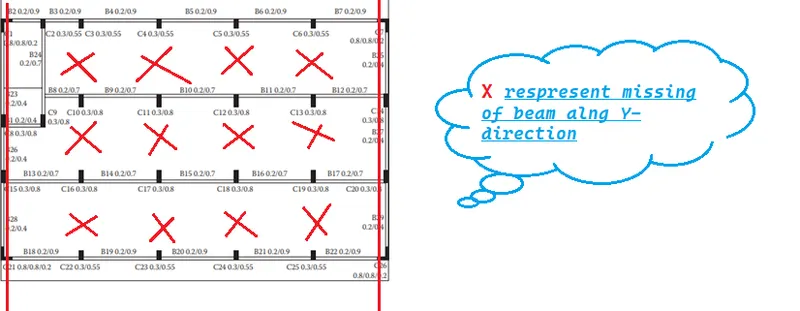 Figure No. 3.11
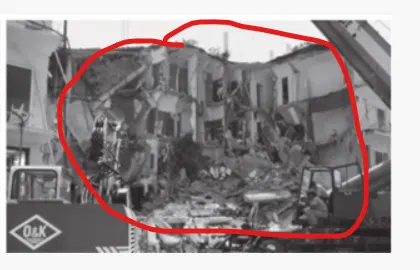 Figure No. 3.12
6). Beams connected along column minor axes:-
As we can see in the plan the longer side of the columns is not connected through X-axis and they are no Y-axis beam connected to the major axis of the column which means more stiffness has appeared in that direction where lesser lateral force appears. There is another reason the major middle portion of the building collapsed completely.
Figure No. 3.13
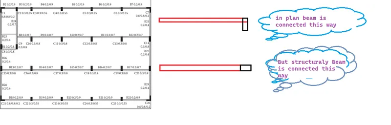 Figure No. 3.14
7). Variations in column sizes:-
As we can see the size of the interior columns are bigger than the exterior the difference in the size of the columns the structural collapse because it may suffer heavy out-of-plan shear force.
The internal columns are higher in size compared to the exterior columns but this will load of significant difference in the lateral drift of columns so the concrete floor might have suffered heavy out-of-plan shear which would lead to the collapse
RESULT:-