Challenge on Combustion
1. Aim, Introduction and Theory:
The major objective of this challenge is to numerically solve and analyse the process of combustion in a combustor model in which methane (CH4) is used as a fuel along with air.A species transport model with turbulence eddy dissipation is used to detrmine the mass fraction of various species such as CH4, CO2, H2O, N2, O2, NOx pollutant and Soot formation. The study is further extended by including the effects of water addition in fuel at different proportions (5% to 30%).
Combustion is a chemically burning process in which the fuel and oxidants are used. Various examples are available such as burning of wood in presence of air and fuel, burning of petrol and diesel in IC engine, burning of LPG gas in a burner, burning of fuel in furnace, burning of gas in gas turbine engines.
Types of combustion models:
a. Turbulent Combustion
Because chemical kinetics are highly nonlinear, turbulence–chemistry interactions should be taken into account to accurately predict turbulent reacting flows. Fluid dynamics software from ANSYS
offers a wide range of turbulence–chemistry interaction models of various complexities suitable for almost every turbulent reacting flow application.
b. Fast Chemistry
The eddy dissipation model (EDM), in combination with the finite rate chemistry model, allows accurate simulation of the heat release and the distribution of the main chemical species for many industrial applications, such as gas turbines, internal combustion engines, furnaces and thrusters. The EDM can be used for all types of combustion as well as in combination with advanced scale-resolving turbulence and multiphase models.
c. Non-Premixed Combustion
With the non-premixed (or diffusion flame) model, the turbulence–chemistry interaction is described using an assumed shape of probability density function (PDF). The thermodynamic state of the fluid, related to the mixture fraction and the chemistry is calculated either from equilibrium or by using a tabulated steady
flamelet approach. The non-premixed model offers a robust and fast solution for any turbulent reacting flow that is at or near chemical equilibrium. This model is often used for gas turbine, process furnace and IC engine applications.
d.Laminar Combustion and Stiff-Chemistry Systems
PDF transport and eddy dissipation concept (EDC) models incorporate detailed chemical kinetics in general turbulent reacting flows for which it cannot be assumed that the chemistry is close to equilibrium
conditions such as flame ignition and extinction, and slowly forming pollutant species. In situ adaptive tabulation (ISAT), chemistry agglomeration and mechanism reduction are available to make detailed
chemistry calculation more efficient and affordable.
2.Solving & Modelling approach:
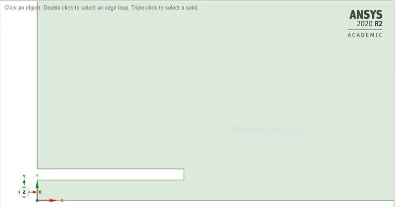
The 3-D model of combustor is initially imported to space claim and by using split body command the the model is splitted about symmetric axis (X-axis), after splitting the required surface for the 2-D model is copied and pated in new design window.
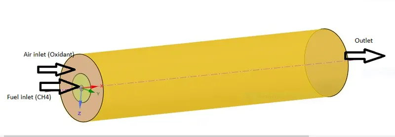
Figure 1. a) 3-D combustor model.
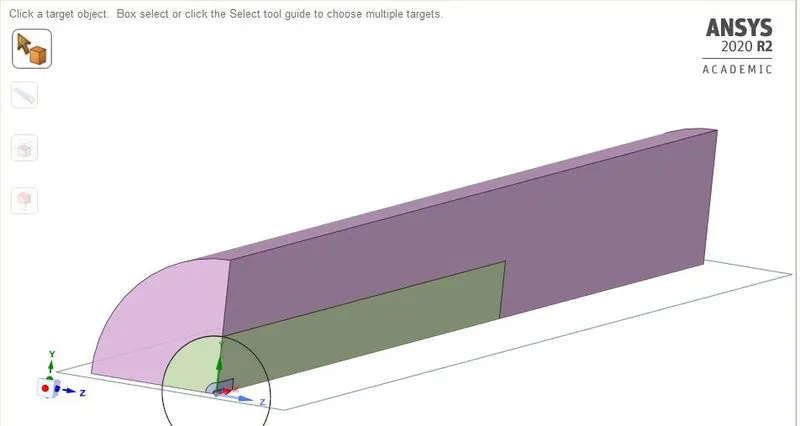
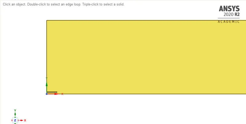
Figure 1. b) split view of combustor Figure 1. c) 2-D model of combudtor.
3.Pre-processing and solver setting:
Meshing:
(a)
(b) (c)
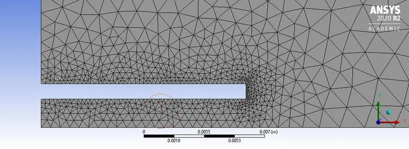
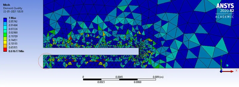
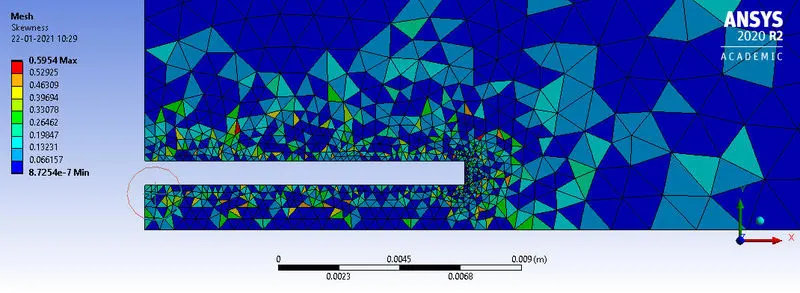
Figure2. (a) Mesh Refinement near the fuel inlet.(b) mesh element quality, (c) Skewness.
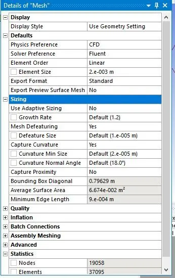
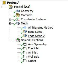
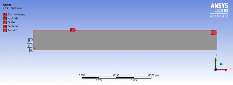
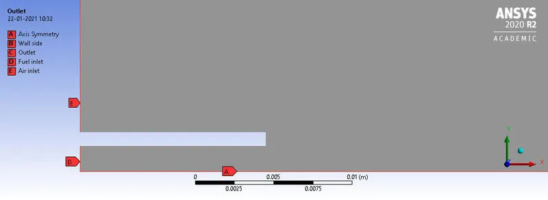
Figure 3. Mesh Set up.
3.1 Solver Settings:
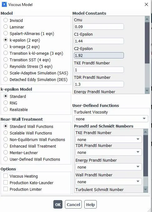
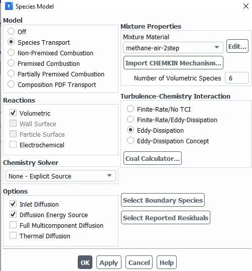
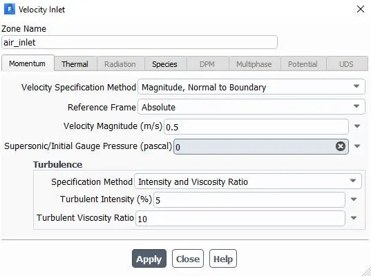
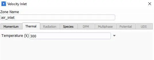
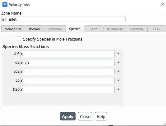
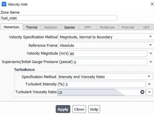
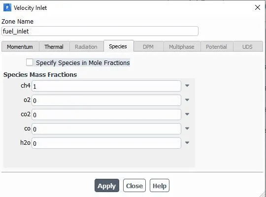
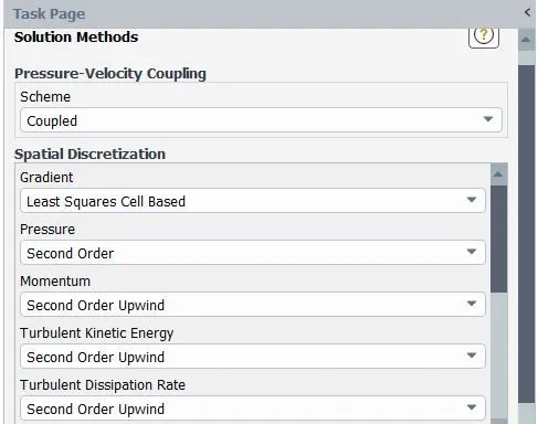
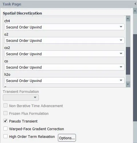
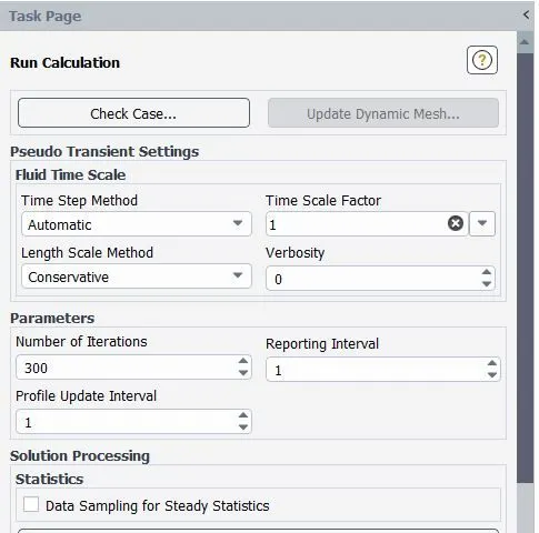
To solve the combustion problem turbulent with eddy dssipation model is used.
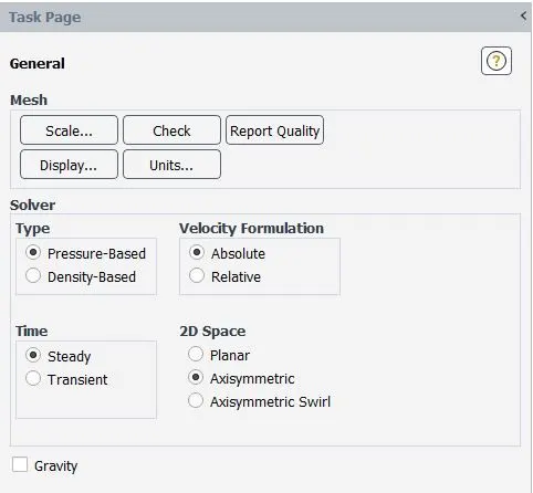

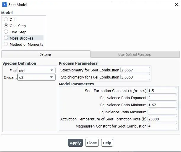
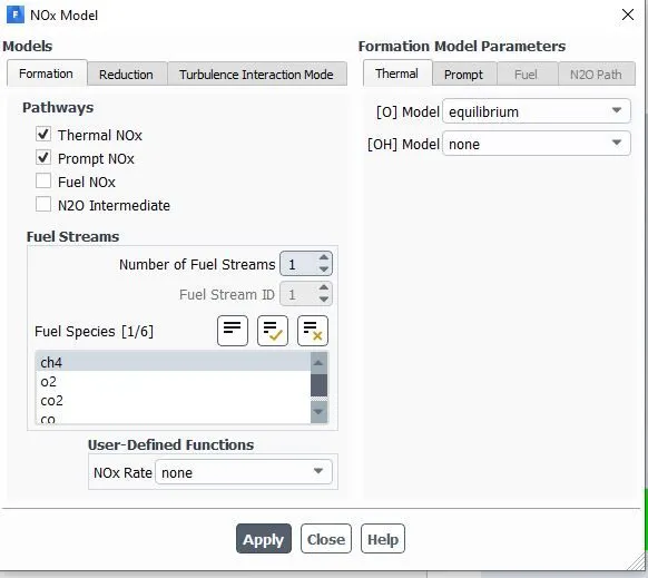
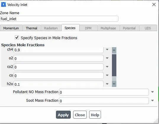
3.2 Set up for NOx Pollutant and Soot Formation:
4.Results:
Part-1 mass fraction of the different species like CO2, H2O, CH4, N2, O2, NOx emissions & Soot formation.
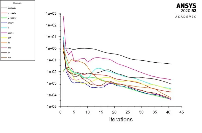
Residual Plot:
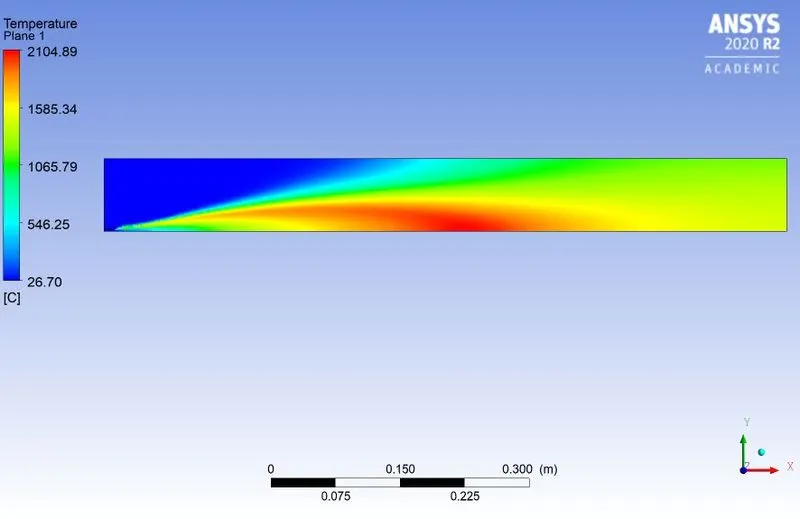
Temperature Contours:
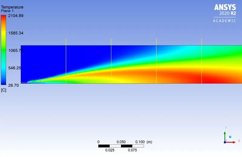
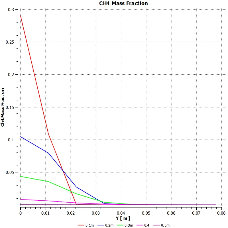
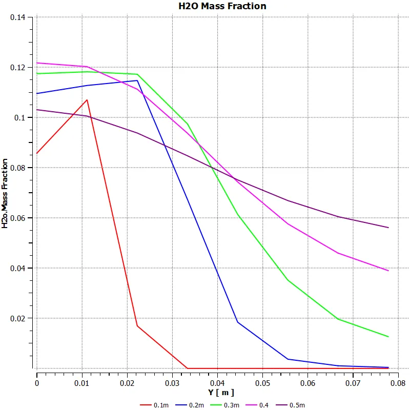
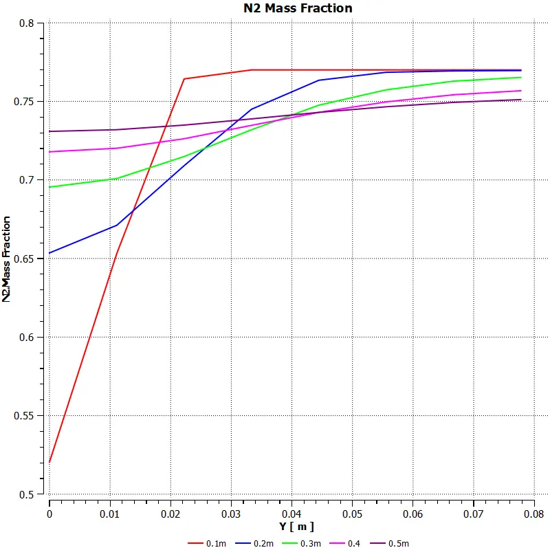
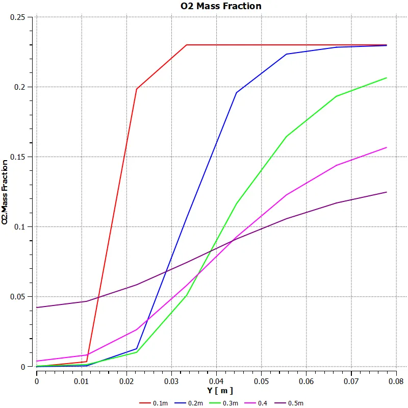
Probe lines at a distance of 100mm each:
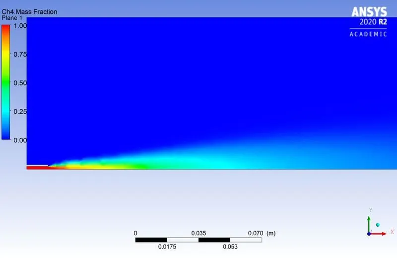
Mass Fraction of CH4:
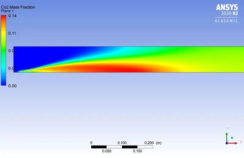
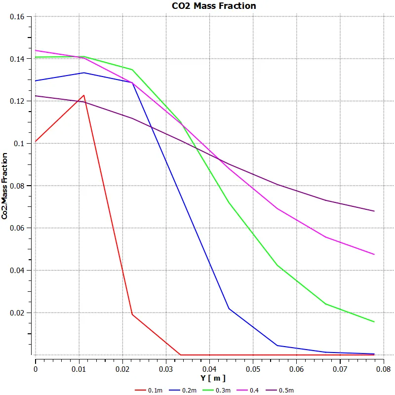
Mass Fraction of CO2:
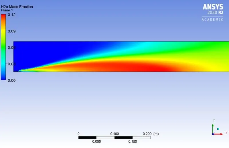
Mass Fraction of H2O:
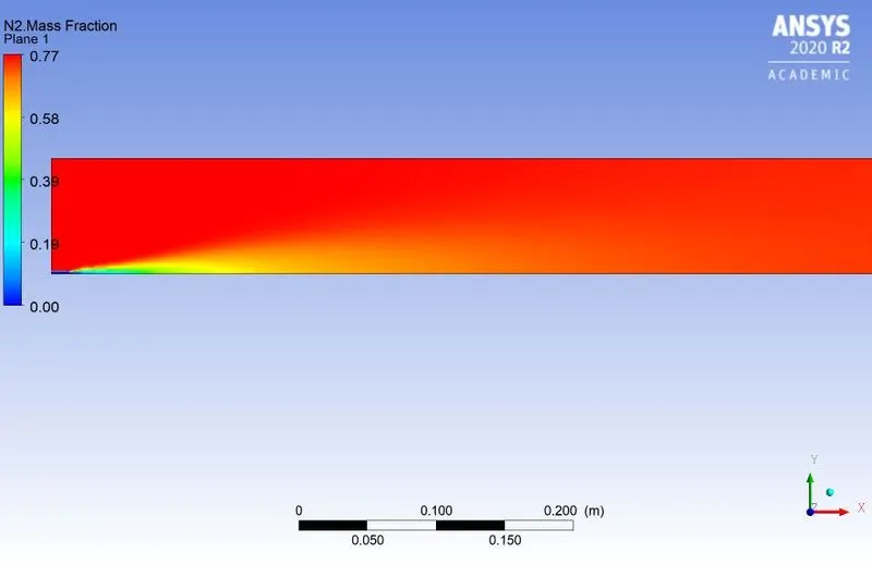
Mass Fraction of N2:
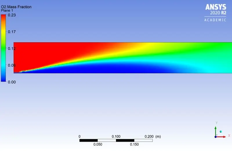
Mass Fraction of O2:
Part-II Effect of water content in the fuel from 5% to 30% by mole.
Case i) 5% water addition in fuel:
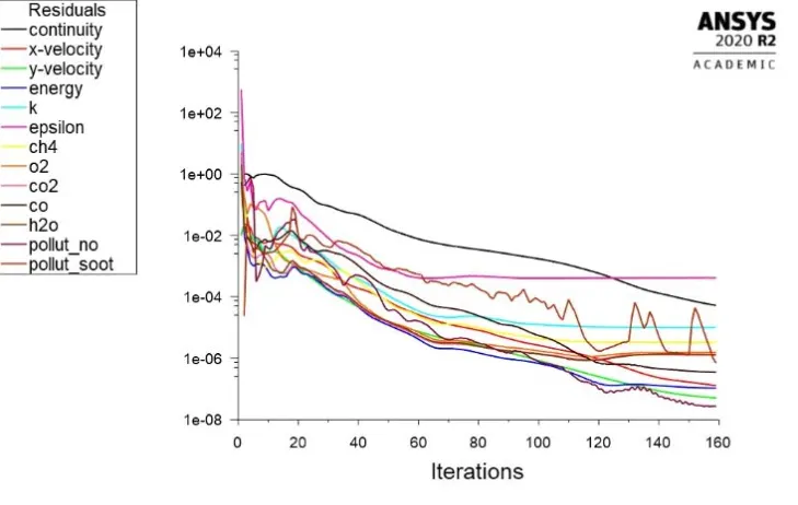
Residual Plots:
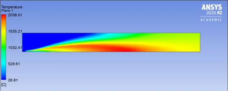
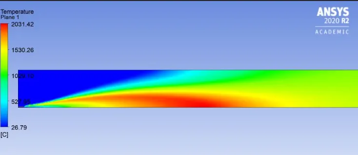
Temperature Contours:
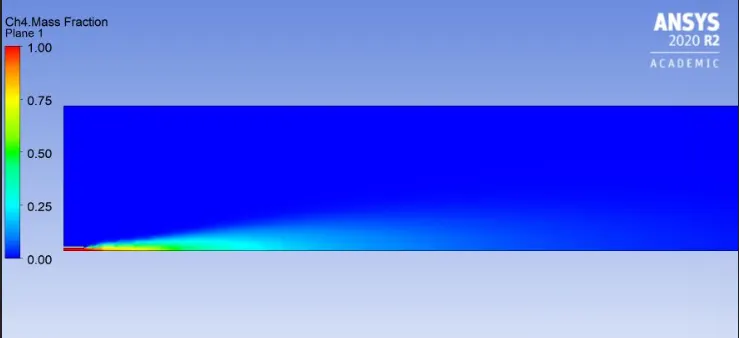
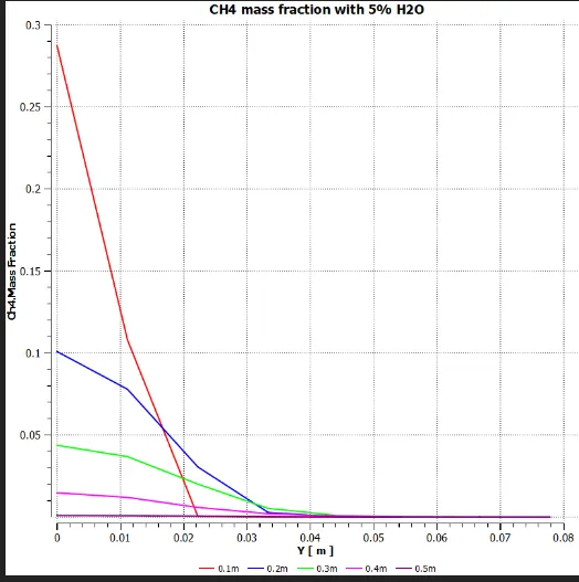
CH4 mass fraction with 5% H2O addition
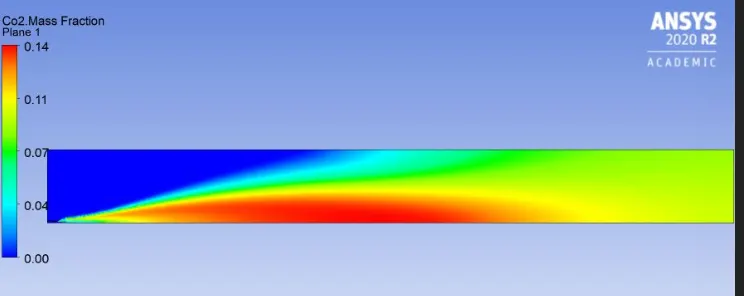
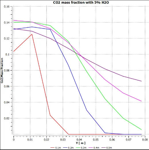
CO2 mass fraction
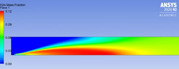
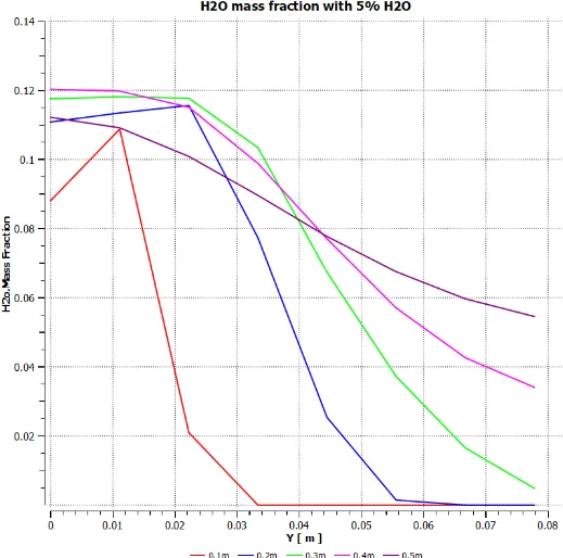
H2O mass fraction:
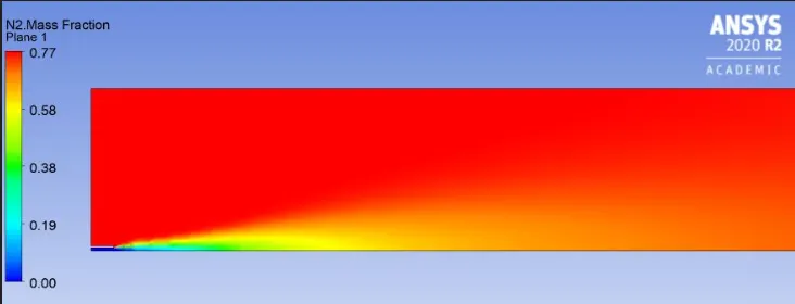
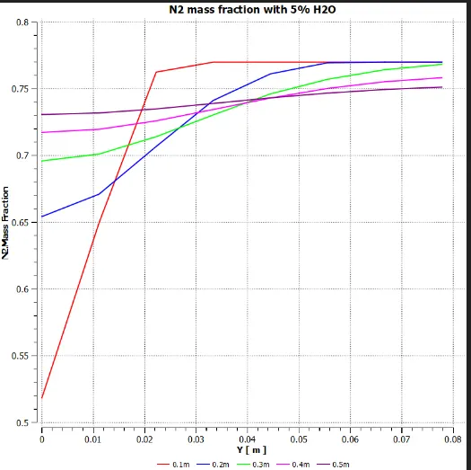
N2 Mass Fraction:
O2 Mass Fraction:
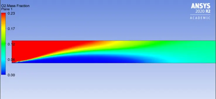
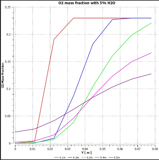
NOx pollutant Mass Fraction:
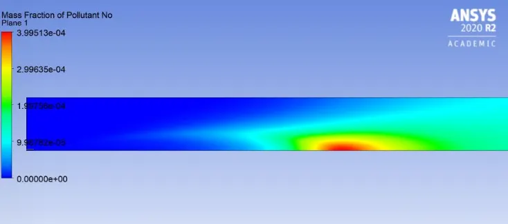
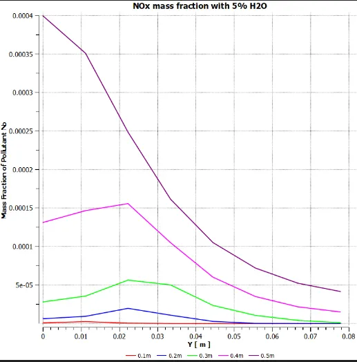
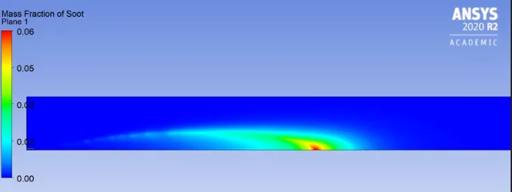
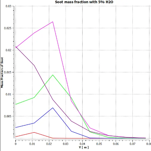
Soot Mass Fraction:
Case ii) 10% water addition in fuel:
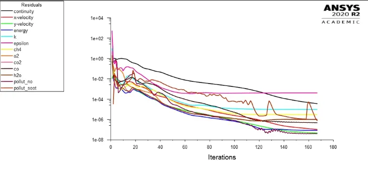
Residual Plots:
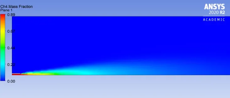
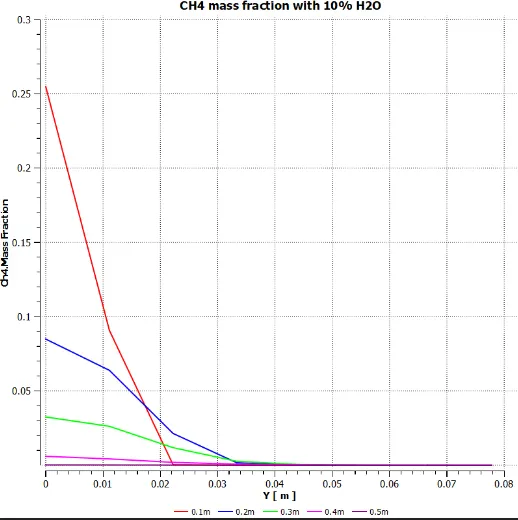
CH4 Mass Fraction:
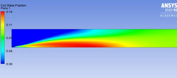
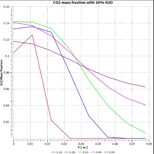
CO2 Mass Fraction:
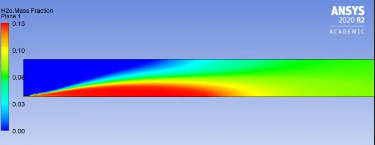
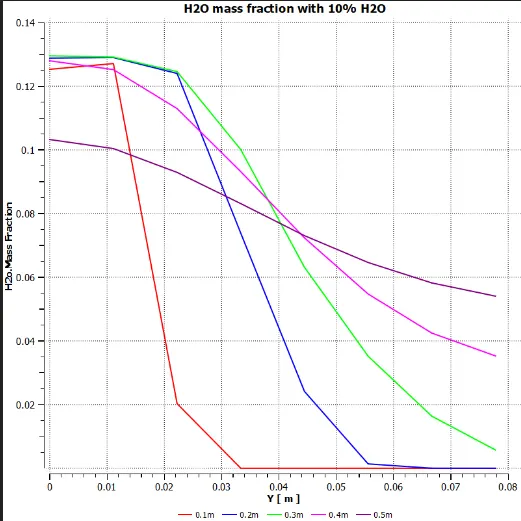
Mass Fraction of H2O:
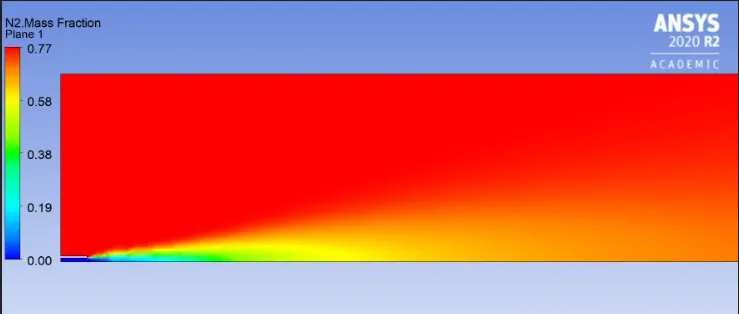
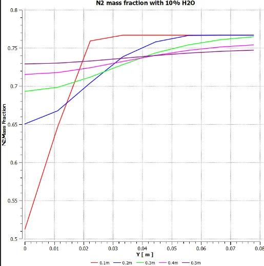
Mass Fraction of N2:
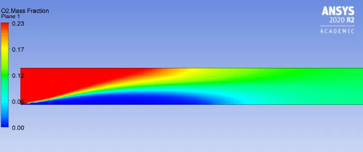
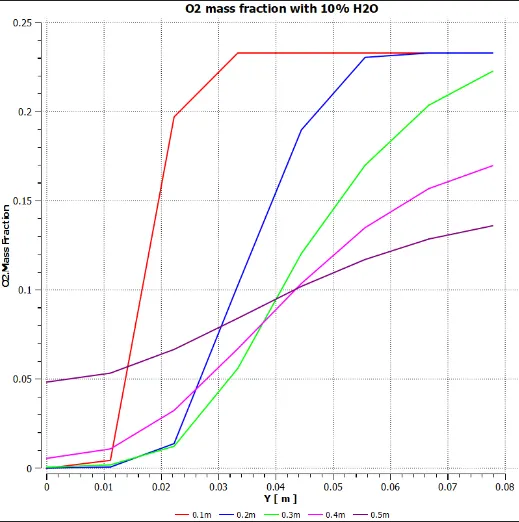
Mass Fraction O2:
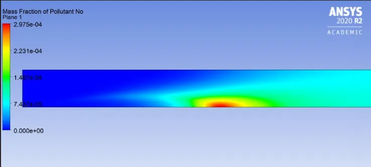
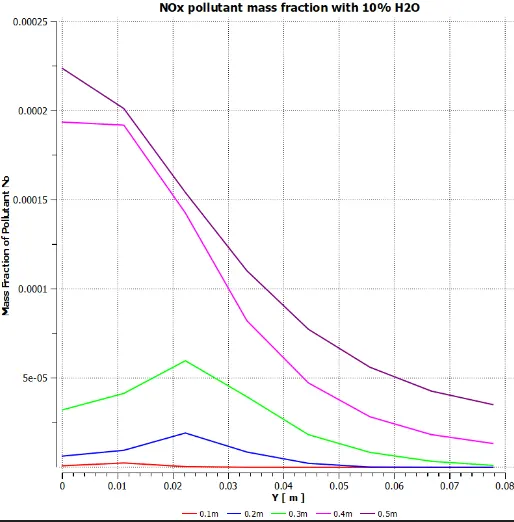
Mass Fraction of NOx pollutant:
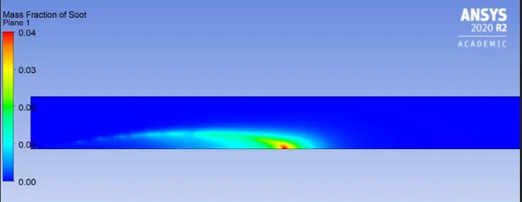
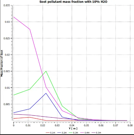
Mass Fraction of Soot :
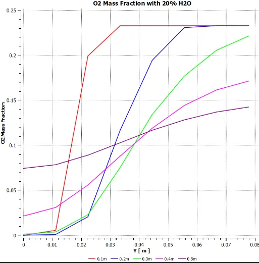
Case-iii) 20% water addition in fuel:
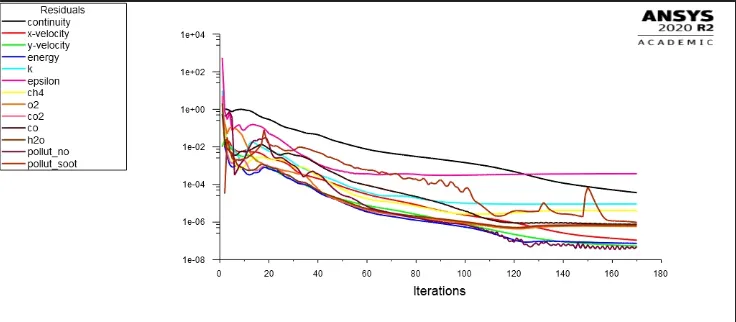
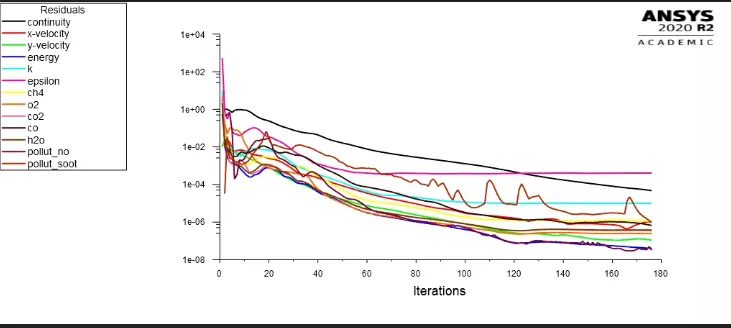
Residual Plots:
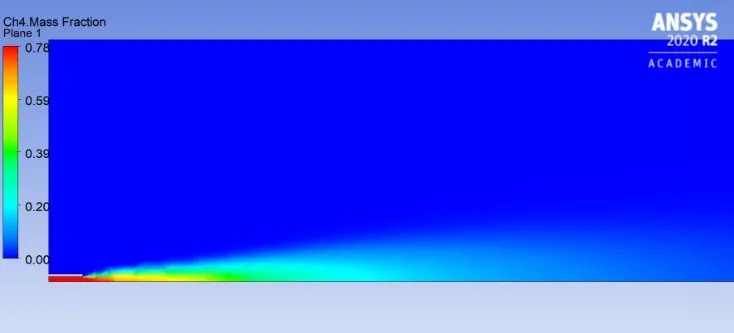
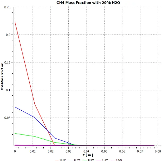
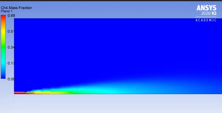
Mass Fraction of CH4:
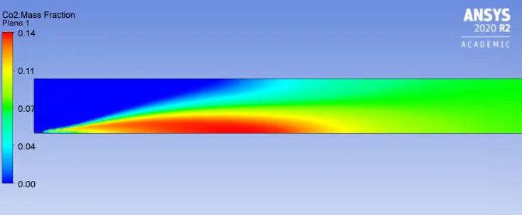
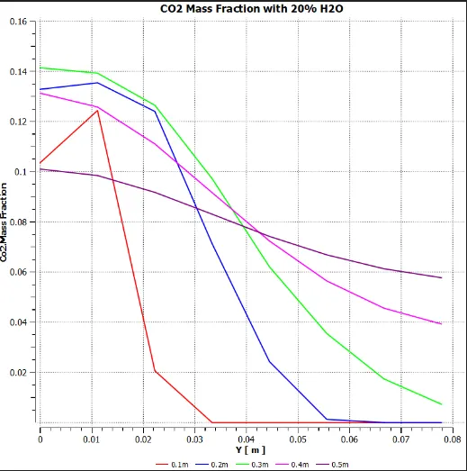
Mass Fraction of CO2:
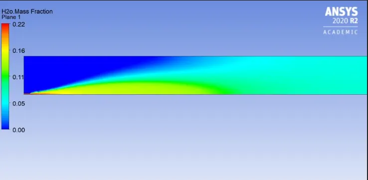
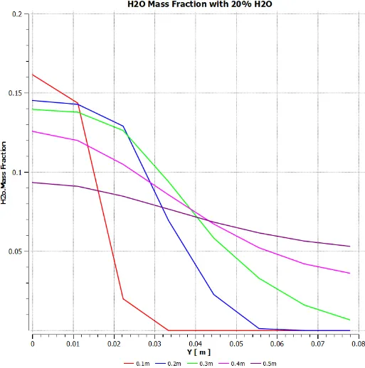
Mass Fraction of H2O:
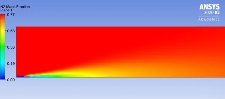
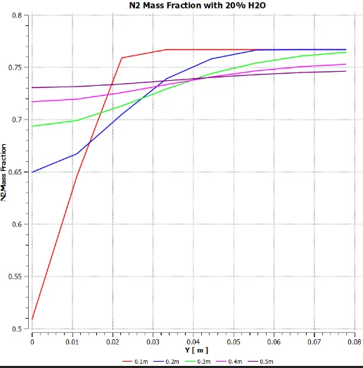
Mass Fraction of N2:
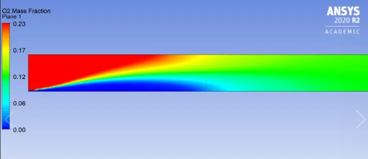
Mass Fraction of O2:
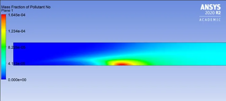
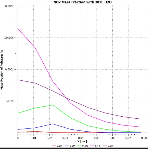
Mass Fraction of NOx Pollutant:
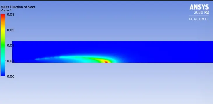
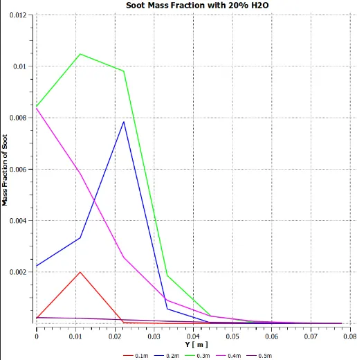
Mass Fraction of Soot:
Case iv) 30%water addition in fuel:
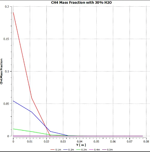
Mass Fraction of CH4:
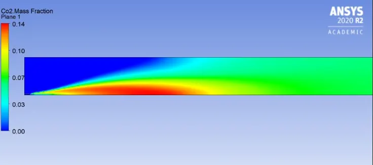
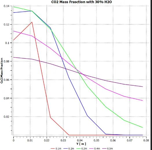
Mass Fraction of CO2:
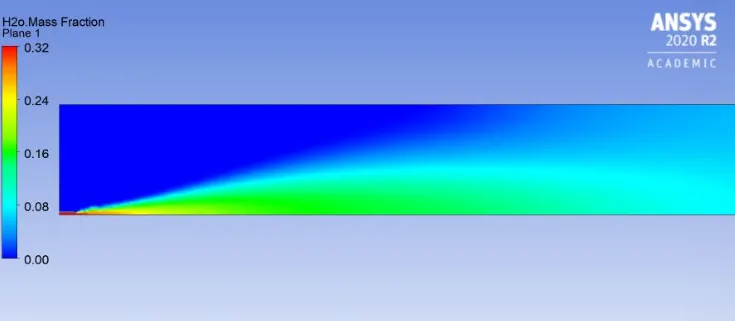
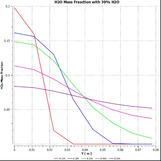
Mass Fraction of H2O:
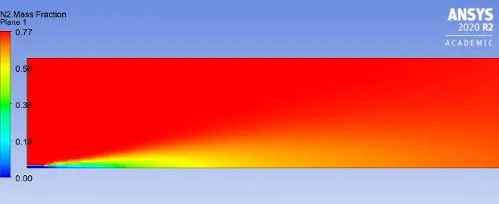
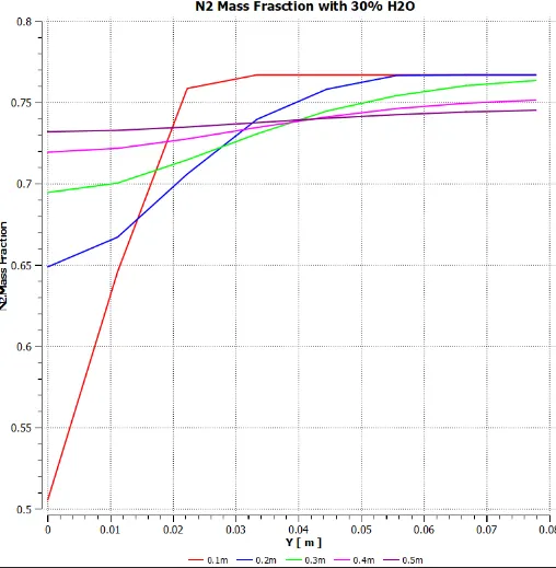
Mass Fraction of N2:
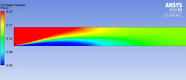
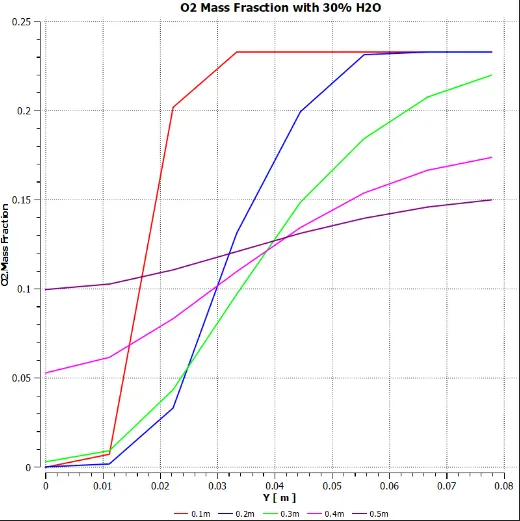
Mass Fraction of O2:
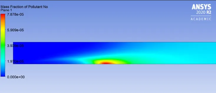
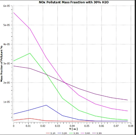
Mass Fraction of NOx pollutant:
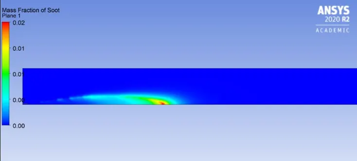
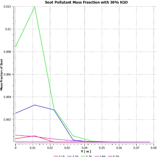
Mass Fraction of Soot:
5.Conclusions:
From the above obtained results the following conclusions are made:
- The maximum temperature in the combustion chamber is located at the center of the chamber.
- The maximum value of mass fraction for H2O and CO2 is observed at a distnace of 400mm in flow direction (Along X-axis).
- The maximum value of O2 and N2 mass fraction is visible at X=100mm and Y=20mm from inlet and remains constant.
- The addition of water in fuel reduces the overall temperature in combstion chamber.
- With increase in the percentage of water addition the NOx pollutant and soot formation decreases.
- The addition of water in fuel have negligible effect on N2 and O2 mass fraction.