Challenge 5 : Concept Modeling of Car Bumper
|
CONCEPT MODELLING OF CAR |
objective
The main of the project is to create a concept model of the bumper of Abarth 500 car, using the curves and surface generation features with the help of Alias software.
INTRODUCTION:
Auto desk alias (formerly known as alias studio tools)
The out side portion of the car which people can see from their naked eye is called CLASS A surface of the car. the surface needs to be designed with the help of which the design of the car can be made and visualised.
in order to make the surface smoother and realistic auto desk alias software is used.This software enables us to make surface smooth as possible with the help of different continuities which can be given to the curves and surfaces.
DESIGN METHODOLOGY:
· The steps that are followed to design the concept model of the front bumper is shown below through flowchat.
· Deciding which views are required to make the care bumper and importing the necessary view
· creating different layers
· generating the curves to trace required shape of the bumper
· generating the surface on the curves to create the concept model of the bumper
· final views of the front car bumper.
1.Importing the front and the side view image of the car.
The image of the view will help us to build the concept model of the bumper.
Steps for importing image
file---import---canvas image---go
scaling the image:
After placing the different views in different layers the blueprints of the car will be scaled down to appropriate size so that it can be positioned accurately with respect to the other views. This will help in generation of curves at appropriate places and with desired shape of the blueprint.
Steps to scale the image:
Press crtl+Shift along with clicking and holding the left mouse button.
Select pick object- select the image
press crtl+ shift along with clicking the middle mouse button
Select scale
hold left mouse button and move up and down to scale the image larger and smaller.
The image is given some amount of transparency so that the curves can be traced easily on it at required positions.
press crtl+shift along with clicking and holding right mouse button.
Select plane editer.
Set the value of the transparency level for the different views of the image in it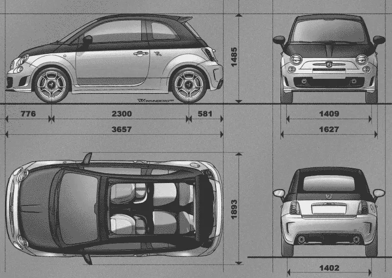
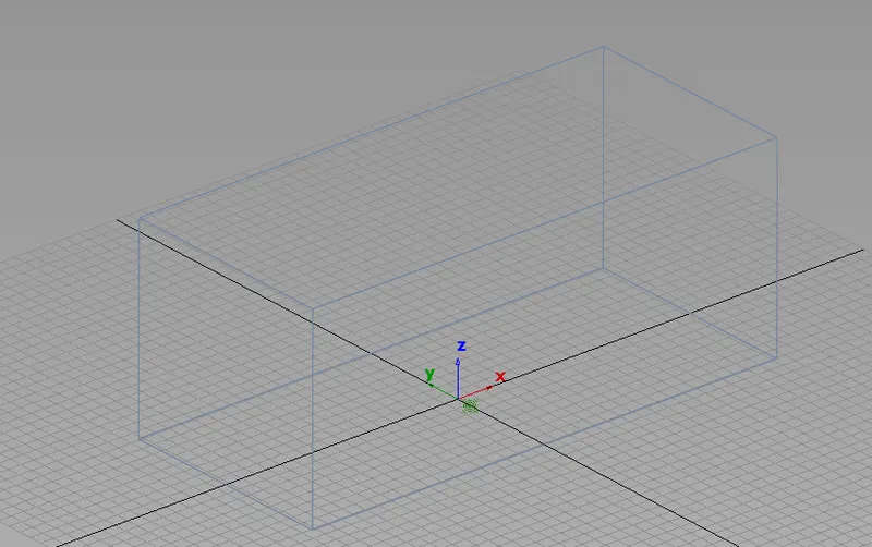
to create the cube to cover the whole car then put tyhe value of the four sides.
To create the planes that use to create the car surface.
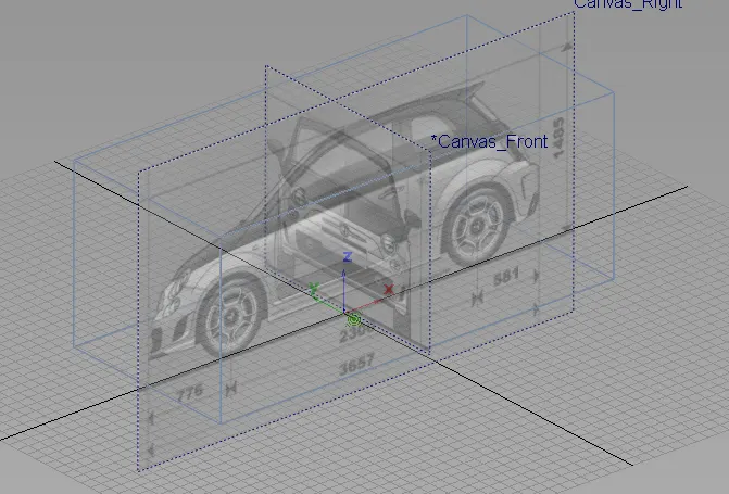
isometric view
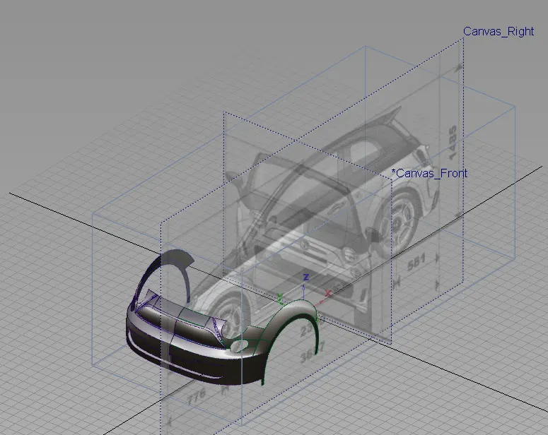
After the file in which the model of the car is being imported, the surface needs to be made with the help of these curves. for this purpose surface features are used which are present inside the palette bar.
The Steps to use the surface generation
features are:
Windows---palette---surface
By following the above procedure the surface generation features can be used.
few of the surface generation features that werev used in this project is listed below.
1.Square
2.Rail
3.Skin
4.ffblend
1. square:
steps to go to square features:
Window---palette ---surface---square
square feature creates surfaces by blending four boundary curves,while maintaining continuity with adjacent surfaces.
GO position--keep the edge exactly
Gltangent---- Try to keep tangency with a surface that shares the edges
G2curvature---Try to keep curvature continuity with a surface that shares this. edge.
2.Rail:
Windows--Palette--surface---Rail
Rail feature create a srface by sweeping one or more profile curves along one or two paths curves (rails).
3.Skin:
Windows--- Plette --surface ---skin
Skin feature is used to create a surface by connecting a set of profile curves.
4.ffblend-Freeform blend
Free form blend enables us to create a transitional surface by selected two input contact lines. These input contact lines can be surface curves or free curves.
To edit the surface,surface edit tools are used to obtain desired shape.
The various surface edit tools used to give desired shape to the surface is shown below:
1.Project
2.Trim
1.Project
this feature is used to create curve on surface of the existing curve which will be projected on the selected surface.
2.Trim
Trim tool trims or splits surface using curves - on-surface or cross sections.
object edit features:
1.Align
2.Extend
3.attach
4.Detach
1.Align:
The align tool moves or reshapes a curve or surface to achieve positional,tangent,orG2 curvature continuity with another curve.
2.extend:
extend tool is used to add to an existing curve or surface by extending from an endpoint or edge.
3.attach:
The attach feature is used to combine two surface together. The attach feature is used to seperate two
4.Detach:
surfaces with the help of curves on surfaces.
diagnostic shade:
Diagnostic shade feature allows us to shade the model using various modes.
purpose of using diagnostic shade feature:
1.show the minimum and maximum curvature on a surface.
2.Shade surface with color.
3.Annotate a model or cloud data.
few of the shades used to check the surface
1.Shadnon: it is off diagnostic shader
the wire frame model is appears with no shading.
2. Mulcol:This shade helps to colour the
surface generated with a single colour.
It is also helps to identify the dents, bumps, and other surface irregularities.
3.Horver:horizontal /vertical hightlighting helps you find surface flaws.
A common use for this is the identification of adjacent surfaces with mismatched of adjacent tangents -in other words, surfaces that do not meet smooothly. you can also usesurface continuity for that purpose,but horizontal/vertical higntlighting gives you a clear view of the surface.
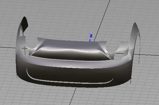
The above image shows the complete concept design of the front car bumper.
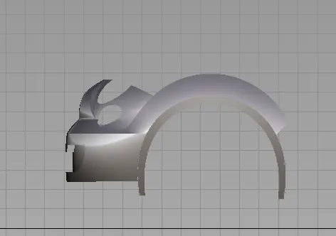
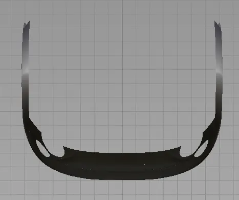
Final views of the car front bumper.
1.Isometric view.
2.side view
3.top view
CONCLUSION:
The complete concept of the car's front bumper is designed with the help of first tracing the curves on the image of the front and side views of the car.
The surface were generated on these curves to complete the design of the bumper.