Challenge 4 : Concept Modelling of Alloy Wheel
Aim - To make an Entire surface Models of Car Rims.
Objective - Our objective here is to make surface models of the car rims, 1) Provided by Skill-Lync and 2) Anyone of Our Choice, Surfacing is to be done using Auto Desk ALIAS
INTRODUCTION
Autodesk Alias (formerly known as Alias StudioTools) is a family of Computer-aided industrial design (CAD) software predominantly used in Automotive Design and Industrial Design for generating Class A surfaces using Bézier surface and NURBS modelling method.
The outside portion of the car which people can see from their naked eye is called the class A surface of the car. This surface needs to be designed with the help of concept modelling technique with the help of which the design of the car can be made and visualised.
In order to make the surfaces smoother and realistic Autodesk Alias software is used. This software enables us to make surface as smooth as possible with the help of different continuities which can be given to the curves and surfaces
- PROCEDURE:
1. Importing the alloy wheel image
The first step in his project is to import the image of the alloy wheel with the help of which the concept model of the wheel will be generated.
Steps for importing Image
File ->Import -> Canvas Image -> Go
Scaling the Image:
After placing the different views in different layers the blueprints of the car will be scaled down to appropriate size so that it can be positioned accurately with respect to the other views. This will help in generation of curves at appropriate places and with desired shape of the blueprint.
Steps to scale the image:
-> Press ctrl + shift along with clicking and holding the left mouse button.
-> Select Pick object - Select the image
-> Press ctrl + shift along with clicking the middle mouse button
-> Select Scale
-> Hold left mouse button and move up and down to scale the image larger and smaller.
Steps to move the image:
Palette -> Transform-> Move.
The image is given some amount of transparency so that the curves can be traced easily on it at required positions.
Steps to set transparency.
Press shift + ctrl along with clicking and holding right mouse button.
Select plane editor.
Set the value of the transparency level for the different views of the image in it.
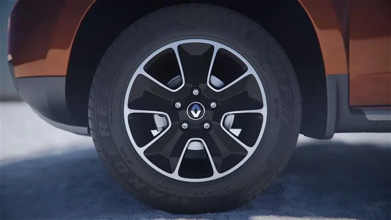
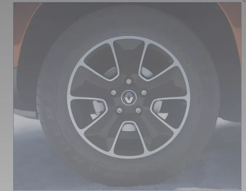
To create the layer by using various command
Layers allow us to organize related objects into groups that you can pick, display, and edit individually or together.
Steps to create Layers
Menu Bar -> Layers -> New
Generation of curves to trace the alloy wheel as per requirement.
After placing the images at required positions the curves are traced on it to give desired shape of the alloy wheel:
Cv Curve - It lets to create new NURBS on the scene by placing CVs.
In order to join curves at few places blends feature is used to give desired shape.
Steps for showing blends bar
Palette -> Blend -> Blend Curve Toolbox ->New
At few places the curves are trimmed to remove curves at certain places where it is not required.
Steps to perform curve trim:
Palette -> curve edit -> crvsct
-> Select the curve -> click on "GO" present in bottom right corner -> select the curve where you want the portion of the original curve to be removed.
The curves for the half portion of the car is made as the other half is exactly the symmetry of it. The curves are made on different layer and then all the curves are assigned in this layer.
The symmetry feature is selected in this layer for the formation of the other half portion of the allow wheel.
As we can observe that the complete wheel is symmetrical, so we need to decide which area we can build the curve network and then perform the symmetry operation to form complete shape of one portion of the wheel.
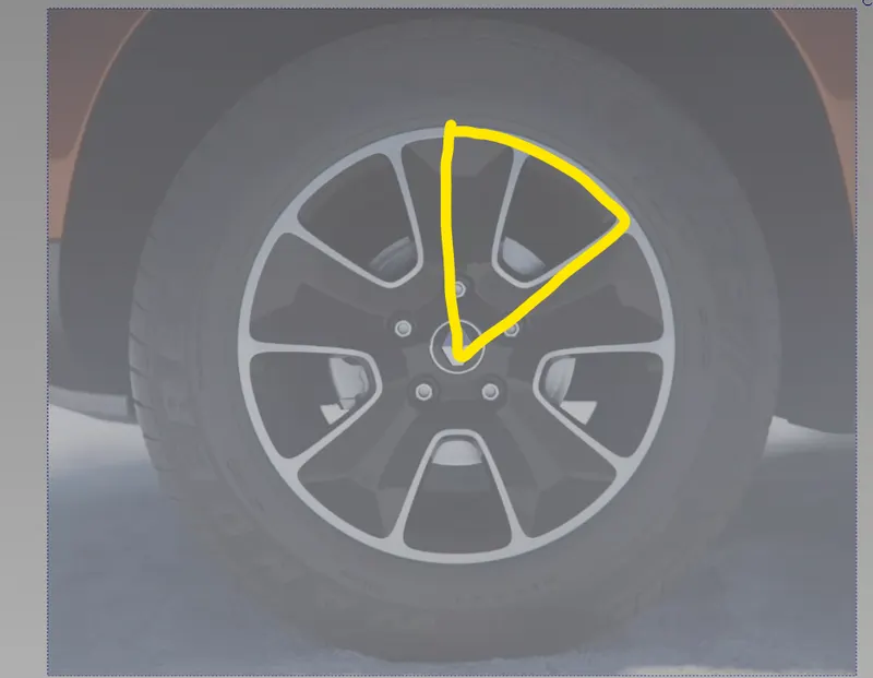
after to create the half of the surface and use symmetry command to another surface.
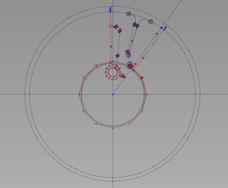
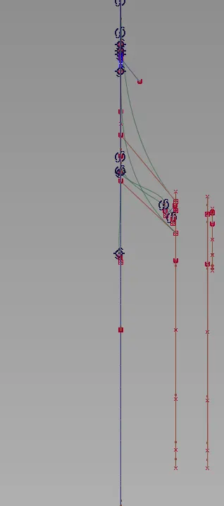
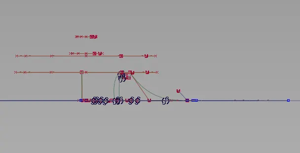
We can observe from the above image that the curve network is traced out in the region we selected, and the inside circlular portion is also traced out so that the shape of the wheel can be designed.
1. Front view
side view
top view
Generation of surfaces for the curve network designed for the alloy wheel.
After the file in which the model of the car is being imported, the surfaces needs to be made with the help of these curves. For this purpose surface features are used which are present inside the palette bar.
Few of the surface generation features
1. Square:
Steps to go to square feature:
Windows -> Palette -> Surface -> Square
Square feature creates surfaces by blending four boundary curves (or curve segments), while maintaining continuity with adjacent surfaces.
Square Control
Continuity Table
Continuity
Free Boundary - This edge is free to move if required by another edge's continuity or by the Influence sliders (see below). This is the default.
GO Position - Keep this edge exactly like the
- boundary curve that created it. In other words, do not let the edge move as with the Free option. This is equivalent to positional continuity.
GI Tangent - Try to keep tangency with a surface that shares this edge.
G2 Curvature Try to keep curvature - continuity with a surface that shares this edge.
Rail
Windows -> Palette -> Surface -> Rail
Skin
Windows -> Palette -> Surface -> Skin
Skin feature is used to create a surface by connecting a set of profile curves.
The various surface edit tools used to give desired shape to the surface is shown below:
1. Project
2. Trim
1. Project
Steps to go to Project feature.
Windows -> Palette -> Surface Edit -> Project
This feature is used to create curve on surface of the existing curve which will be projected on the selected surface.
This is like shining a flashlight at the curve, and turning the shadows on the target surfaces into curves-on-surface. The line between the flashlight, the curve, and the shadow is the projection vector.
2. Trim
Steps to go to Trim feature:
Windows -> Palette -> Surface Edit -> Trim
Trim tool trims or splits surfaces using curves-on-surface or cross sections.
after do that all features and some commands to complete that surface
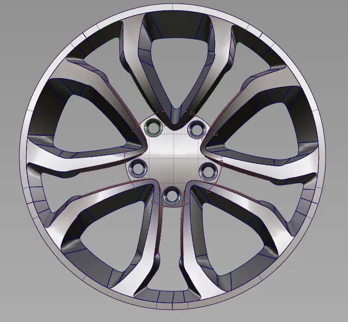
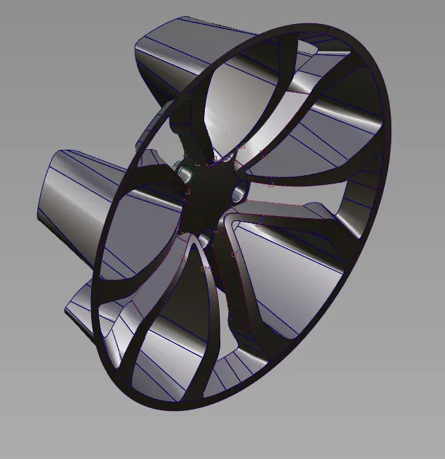
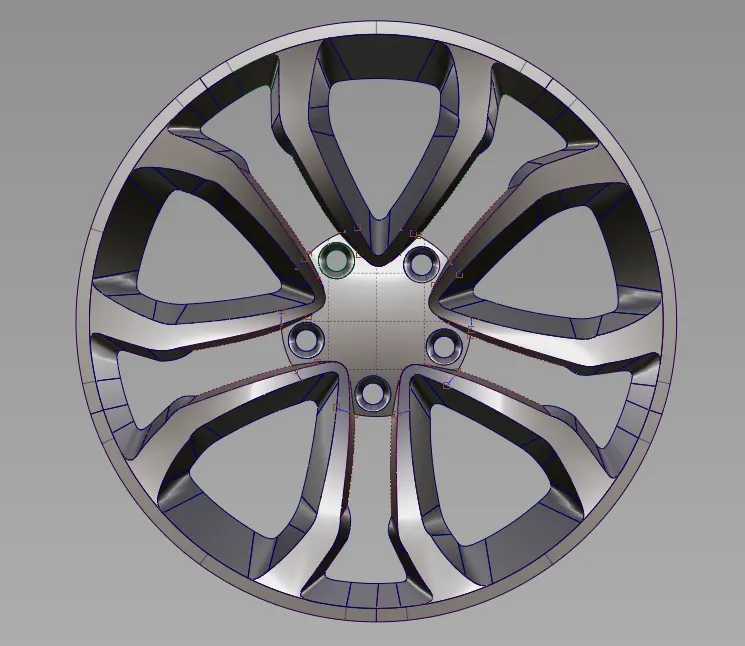
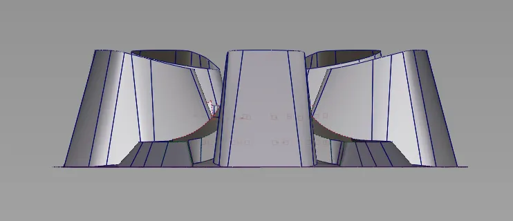
After completing the generation of surfaces with the help of features in surface, surface edit, object edit, etc, the complete concept design of the alloy wheel is generated.
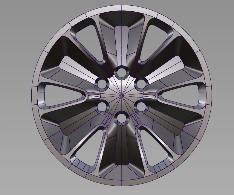
Different views of the alloy wheel.
1. Isometric view:
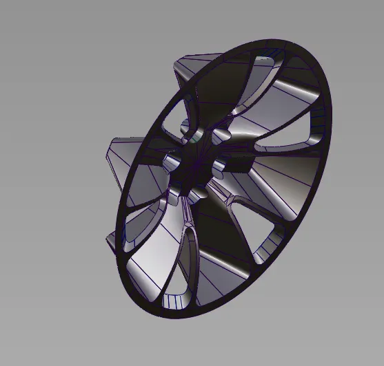
front view
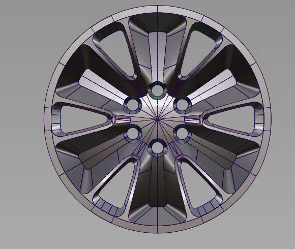
top view
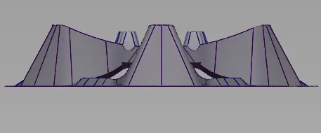
Side view:
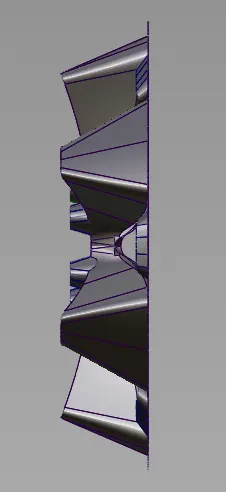
to create the another alloy wheel for my favourite surface by using some technique taught by the videos to create the own wheel alloy
image of another wheel alloy

curve network
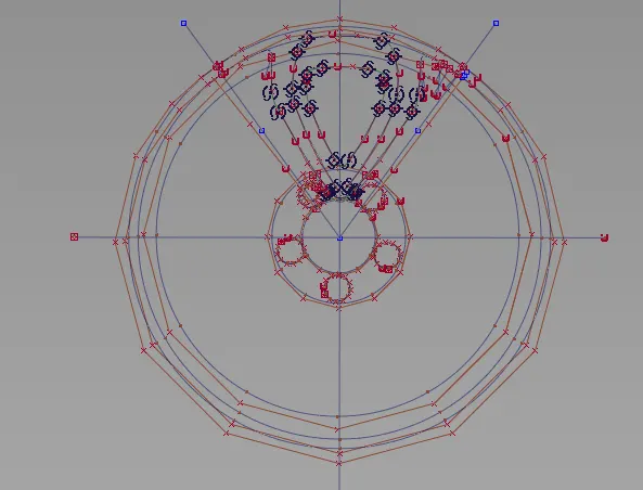
to follow same procedure to make the surface
different views
CONCLUSION
The complete concept design of the alloy wheel is designed with the help of surface and curve generation features using alias.