Centrifugal pump design and analysis
CENTRIFUGAL PUMP DESIGN AND ANALYSIS BY FLOW SIMULATION IN SOLIDWORK’S
AIM:
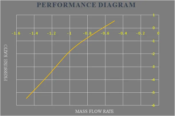
The purpose of this analysis is to draw the performance diagram by create an approximate 3D model of a centrifugal pump and then find out the pressure ratio and mass flow rate using solidworks flow simulation.
INTRODUCTION:
Computational fluid dynamics is a branch of fluid mechanics that uses numerical analysis and data structures to analyse and solve problems that involve fluid flows. Here solidworks flow simulation is an intuitive computational fluid dynamics solution embedded within solidworks 3D CAD that enables you to quickly and easily simulate liquid and gas flows through and around your designs to calculate product performance and capabilities.
So solidworks flow simulation is playing major role in CFD and using this software we are going to analysis the centrifugal pump performance at various conditions. Because centrifugal pump is most important mechanical device in hydraulic system to transmit fluids. Also its geometric design must be perfect like impeller, vanes and volute casing to give the require outputs. Based on the design parameters we can give an input to it like drive shaft speed.
THEORY:
Centrifugal pumps are used to transport fluids by the conversion of rotational kinetic energy to the hydrodynamic energy of the fluid flow. The rotational energy typically comes from an engine or electric motor. The fluid enters the pump impeller along or near to the rotating axis and is accelerated by the impeller, flowing radially outward into a diffuser or volute chamber (casing), from which it exits. Common uses include water, sewage, agriculture, petroleum, and petrochemical pumping. Centrifugal pumps are often chosen for their high flow rate capabilities, abrasive solution compatibility, mixing potential, as well as their relatively simple engineering. The reverse function of the centrifugal pump is a water turbine converting potential energy of water pressure into mechanical rotational energy.
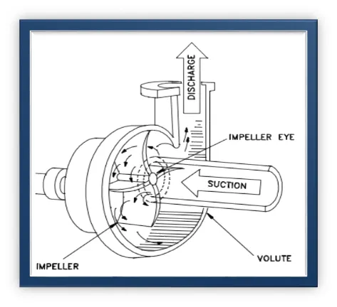
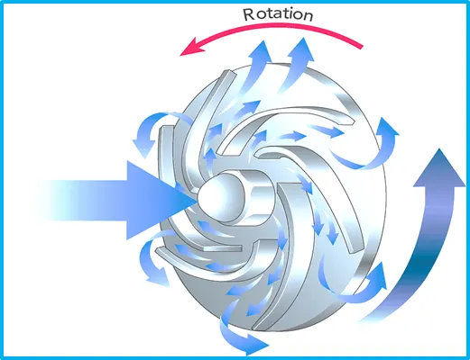
Working principle: The impeller is the key component of a centrifugal pump. It consists of a series of curved vanes. These are normally sandwiched between two discs (an enclosed impeller). For fluids with entrained solids, an open or semi-open impeller (backed by a single disc) is preferred. Like most pumps, a centrifugal pump converts rotational energy, often from a motor, to energy in a moving fluid. A portion of the energy goes into kinetic energy of the fluid. Fluid enters axially through eye of the casing, is caught up in the impeller blades, and is whirled tangentially and radially outward until it leaves through all circumferential parts of the impeller into the diffuser part of the casing. The fluid gains both velocity and pressure while passing through the impeller. The doughnut-shaped diffuser, or scroll, section of the casing decelerates the flow and further increases the pressure.
MAJOR PARTS OF CENTRIFUGAL PUMP:
The major components of the centrifugal pump are given below in detail.
1) Casing: The casing is a narrow air passage around the impeller. It designs in such a shape that it converts the fluid kinetic discharges by the impeller outlet energy into pressure energy before the fluid exits the casing and inserts into the discharge pipe. The casing includes in the major components the centrifugal pump
2) Suction Pipe: The bottom side of the suction pipe immerses in the water to that we want to lift while other side connects with the inlet of the centrifugal pump. This part of the centrifugal pump has a foot and strainer valve at its bottom end. The role of these valves is to remove debris like sands, leaves, and allow the water to flow upwards.
3) Rotating Parts: These parts of the centrifugal pump consisting of an impeller and a shaft:
4) Delivery Pipe: This part of the centrifugal pump uses to lift fluid to the required area. One end of the delivery pipe connects with the outlet of the pump, and the other end connects with the height where we want to transfer fluid.
FLOW SIMULATION SETUP:
Open the solidworks part file, and then start the 3D design of a centrifugal pump with approximate dimension values. Here the important thing is the rotation of drive shaft doesn’t achieve by solidworks as actual centrifugal pump working function. So I had designed the rotating region or volume to let solidworks know that and it encompassed the impeller. Finally save your design and using lids close both the flow inlet and outlet. After that follow the following condition to run the simulation process properly.
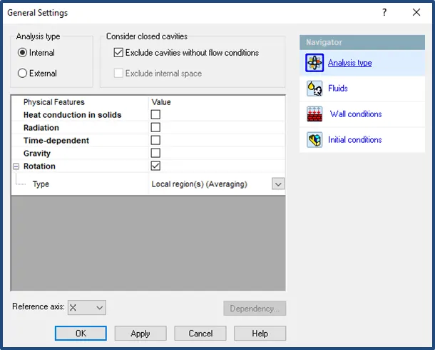
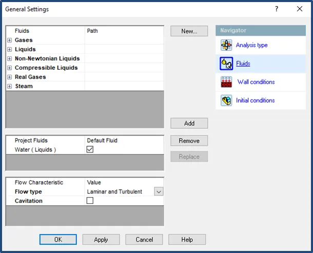
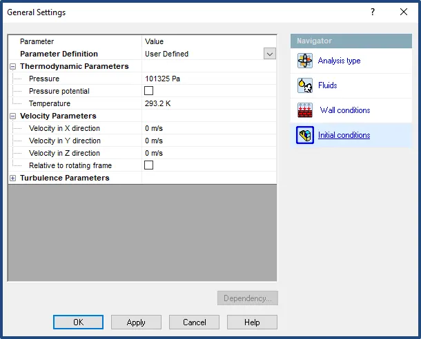
i)Initial conditions: Create the new flow simulation using the wizard comment. Here I had given project name, analysis type, fluid, wall conditions and initial conditions. These given parameters are the input value to start up the simulation process, because our result is based on that. And I used rotation physical feature in analysis type, because the process is based on input drive shaft rotating speed. Finally, the working fluid for this simulation is water.
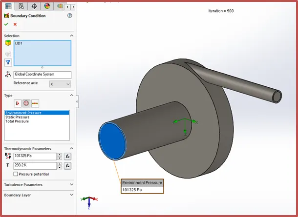
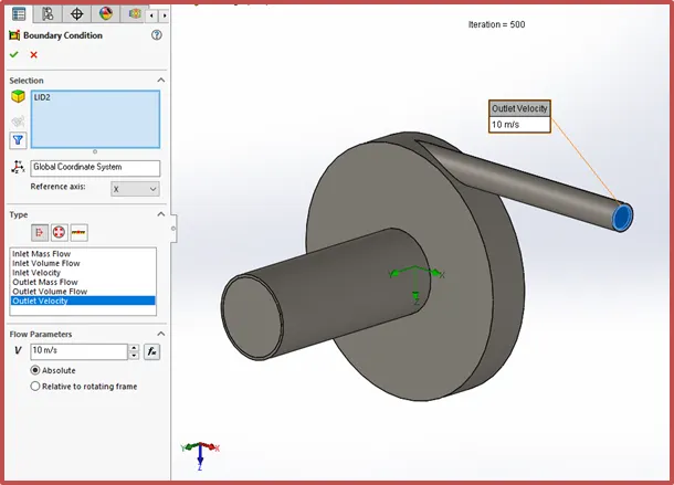
ii)Boundary condition: I have assigned the inlet flow as environment pressure opening and its value is 1bar this is an atmospheric pressure. Also the outflow as outlet velocity and it was taken as 10m/s this value will change up to 30m/s to find out the mass flow rate and pressure loss as well.
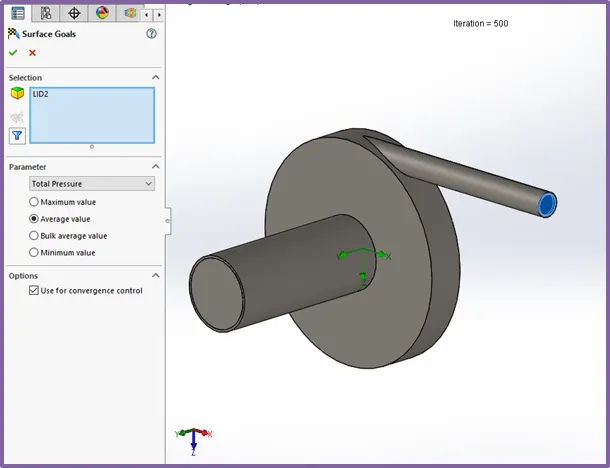
iii)Goal: we can insert the five types of goals based on which type of result you want. So here I have taken the surface goal for mass flow rate, total pressure in outlet and total pressure in input. Mass flow rate is one of the factor to identifying the maximum flow of water corresponding to outlet velocity.
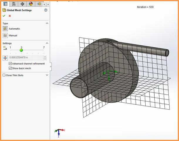
iv)Mesh: The process of subdividing the model into small pieces is called meshing. In solidworks the mesh is create automatically with recommended value. If you increase it then the result will come up with more precious. We have two type of meshing one is automatic and another one is manual. Here I have taken the recommended automatic mesh level with advanced channel refinement.
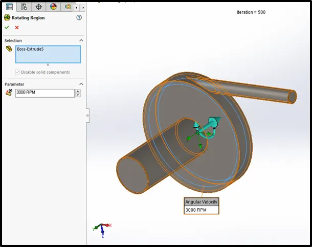
v)Rotating region: It’s like a cylinder around the impeller but it not merged with impeller and volute casing. And it is not considering as a component during process and assigned as rotating region with 1000rpm.
RESULT:
After completing my analysis process, I have obtained some results based on goals which I was assigned before run this flow simulation. That results are given below:
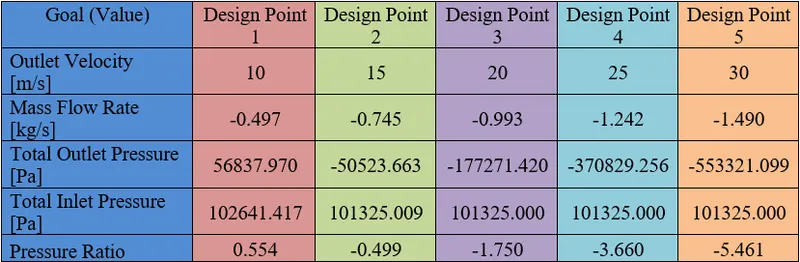
Here the set value (outlet velocity) is gradually increasing by 5m/s up to 30m/s and inlet pressure is constant. Also that impeller is rotating at constant speed.
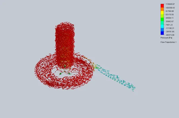
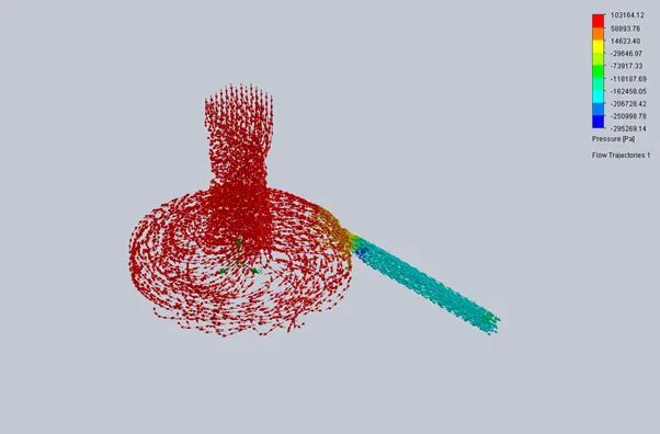
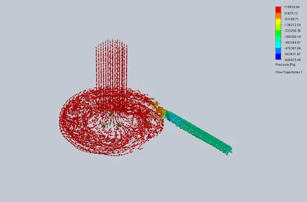
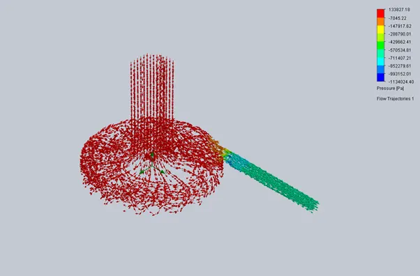
So if I increase the outlet velocity at the same time the mass flow rate increasing in negative range. The outlet pressure also increasing in negative range because of high outlet velocity causes maximum vacuum in pump casing. You can understand it in following trajectories.
VO=10m/s
VO=15m/s
VO=20m/s
VO=25m/s
VO=30m/s
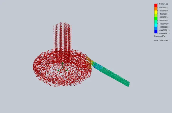
The following performance diagram will give the detail clarity about how centrifugal pump work on various outlet velocity and constant rotor speed of 1000rpm.