Centrifugal pump design and analysis
AIM :
To design a 3D model of centrifugal pump ,run a baseline flow simulation where inlet flow takes place and then perform a parametric study for different velocities and then to obtain the relationship between Pressure ratio and mass flow rate.
3D Model
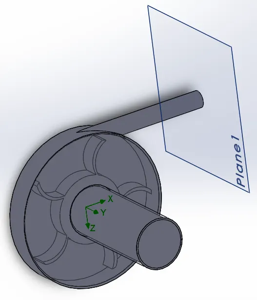
Parameters:
Internal flow simulation
Steady-state study
Temperature: 293.2K
Medium: Water
Rotation: On and at 1000 rad/s
Boundary conditions:
Inlet pressure: 101325Pa
Outlet velocity at exit: 10m/s
FLOW ANALYSIS
For this test, the input variables are outlet velocities at 10, 15, 20, 25 and 30 m/s and the automatic level of mesh is 3. The number of iteration for this test is 500 and mesh refine is set to advanced channel refinement.
RESULTS:
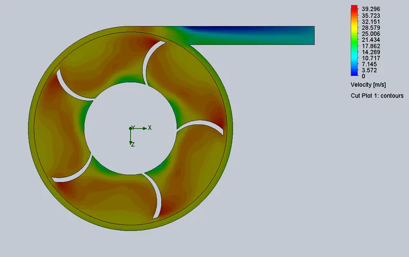
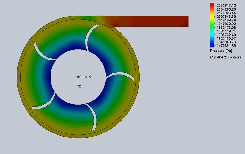
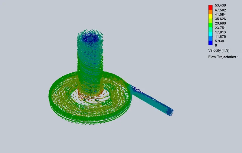
Design Point 1 at 10 m/s
Velocity plot
Pressure plot
Flow Trajectory
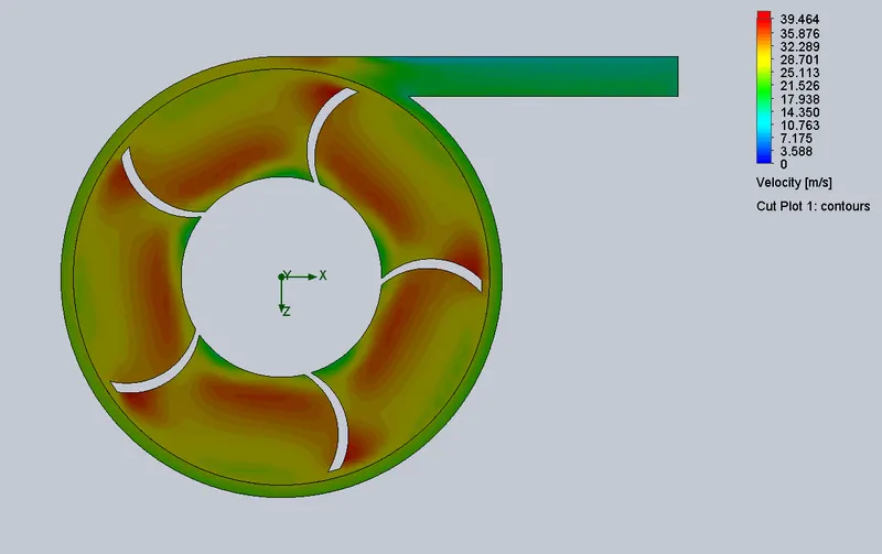
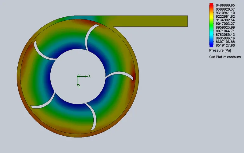
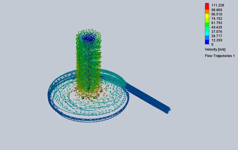
Design Point 2 at 15 m/s
Velocity plot
Pressure plot
Flow Trajectory
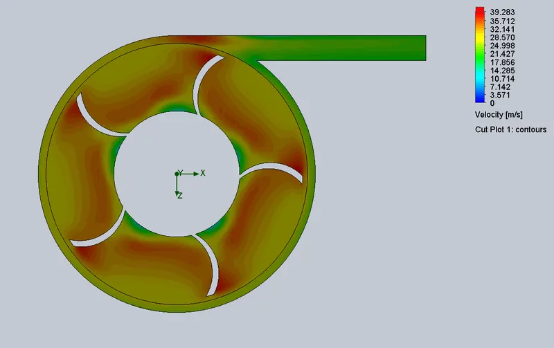
Design Point 3 at 20 m/s
Velocity plot
Pressure plot
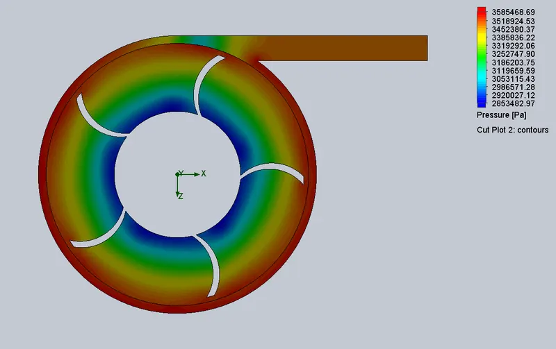
Flow Trajectory
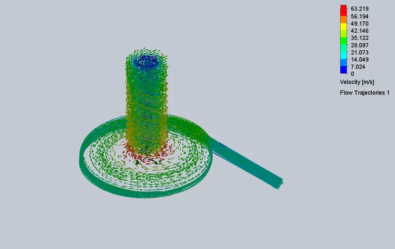
Design Point 4 at 25 m/s
Velocity plot
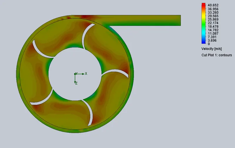
Pressure plot
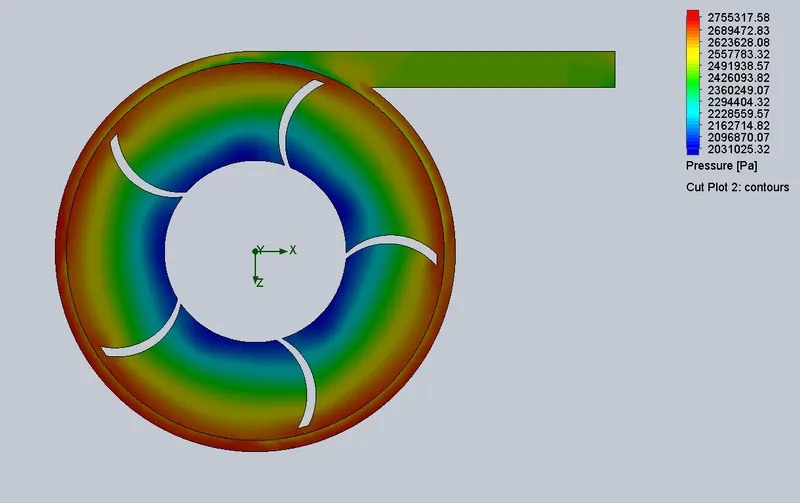
Flow Trajectory
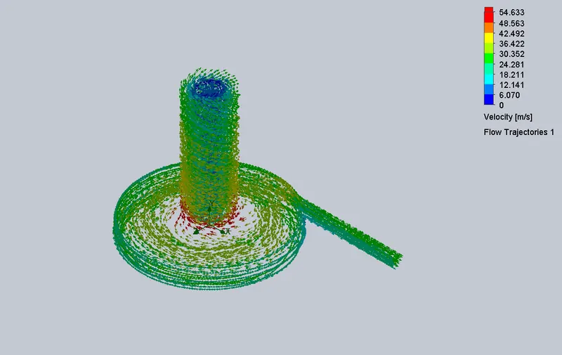
Design Point 5 at 30 m/s
Velocity plot
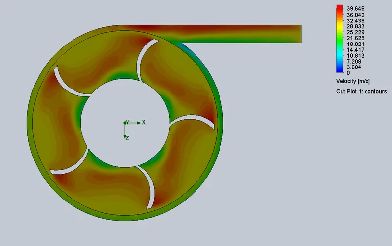
Pressure plot
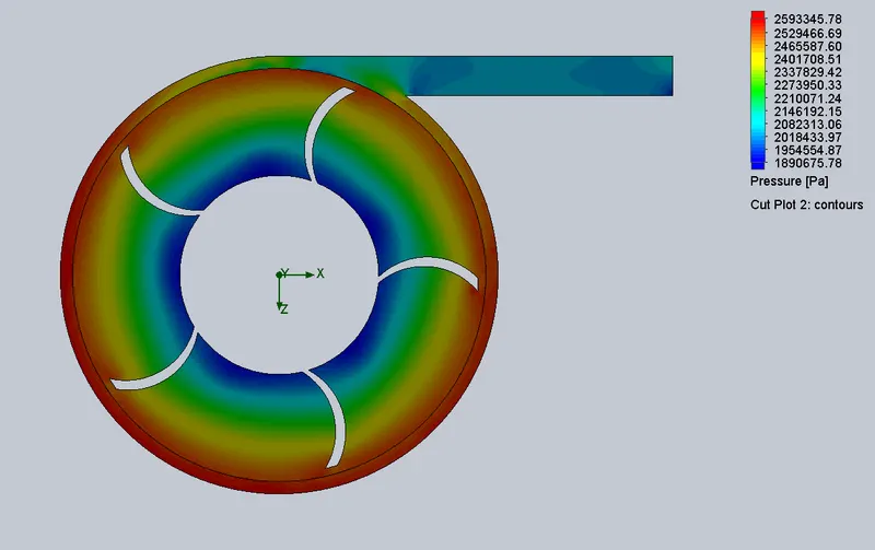
Flow Trajectory
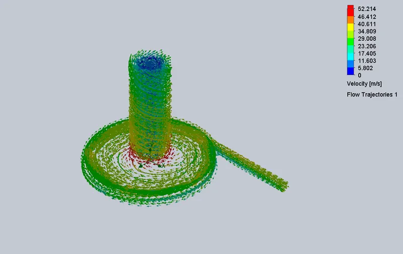
Parametric study:
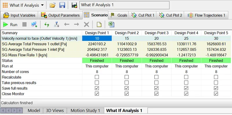
Surface goals of Mass Flow Rate:
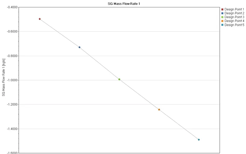
Mass Flow Rate is treated as negative whenever it leaves the domain.
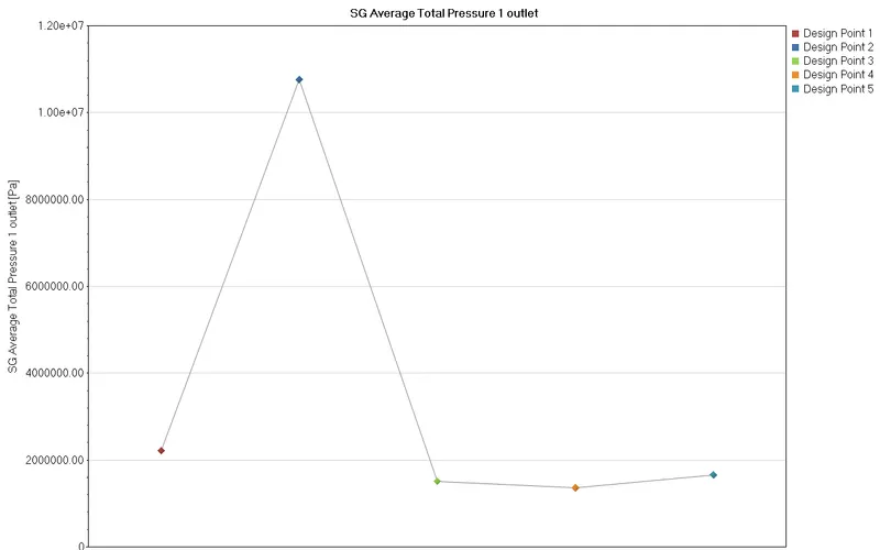
Pressure Outlet:
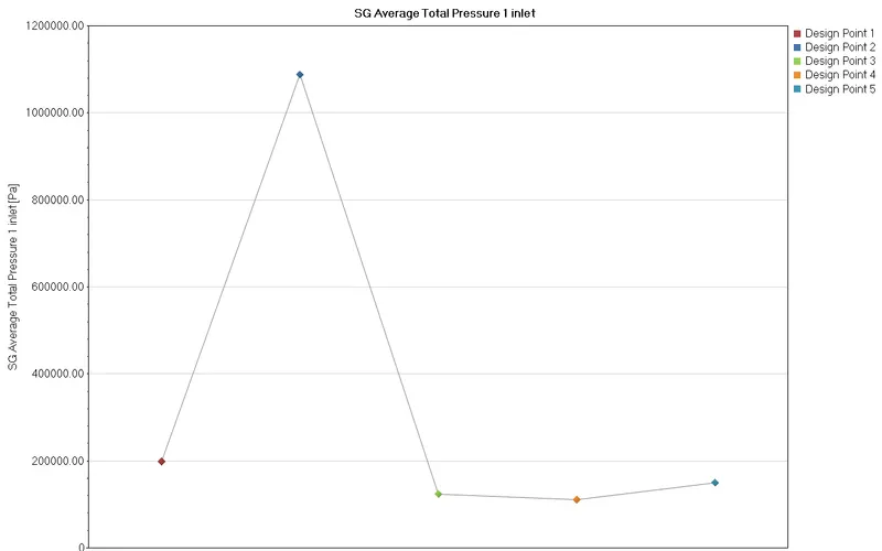
Pressure Inlet:
Pressure Ratio:
Pressure ratio = (Outlet total pressure)/( Inlet total pressure)
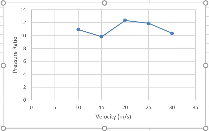
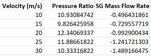
Graph of Pressure ratio and Mass flow rate:
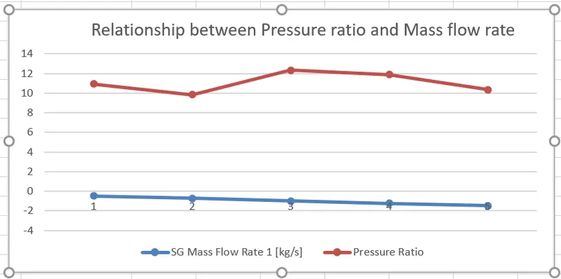
INFERENCE:
As outlet velocity increases ,the pressure decreases and the mass flow rate increases.