Buckling Analysis on a cyclone separator stand with and without metallic stiffener using Solidworks.
Aim
To perform a Buckling Analysis on a cyclone separator stand with and without metallic stiffener using Solidworks. And to perform Design study to optimize the position of the stiffener so that maximum Buckling factor of safety could be achieved.
Objective:
- To apply a load of 150kN and find out deflection.
- To create a metallic stiffener on the legs of the stand and run the analysis to find out the change in buckling factor of safety.
- To Run the design study and find the optimum position for the stiffener.
- Compare the results for all the cases using table and highlight the best one.
Introduction:
Buckling (Lateral deflection of the bar)
Buckling is the phenomenon by which a medium or long column fails by a combination of bending and compression. As the axial load is increased, the column tends to buckle or bend. For small values of the load the column remains in stable equilibrium returning to its straight position when the load is removed. As the load is increased, the column gets a permanent deflection even after the lateral load is removed. The column is in a deflected, neutral equilibrium position. Further increase in the load causes more deflection and the column fails. Such a failure is known as buckling.
Due to many factors, long columns show buckling. The load may not be truly axial or the column itself may have a centre line which is not straight initially.
This makes long columns behave much differently from short columns. In the case of short columns, lateral deflections as well as bending stresses are small, and direct stresses dominate. For long columns, however, bending stresses become significant.
Working Stress and Factor of Safety
Many times, the performance of the material under working loads and conditions is of interest. In any structure, it is ensured that the stress in the material under normal conditions is much below the ultimate strength or yield strength. Such a stress is known as the working stress, and is obtained by dividing the ultimate strength, or yield strength as in the case of steel, by a safety factor. The safety factors are specified in the case of all materials in the respective codes. The factor of safety on stress is, for example, 3 in the case of concrete on ultimate strength and 1.68 in the case of steel on yield stress.
Stiffener
Stiffeners are secondary plates or sections which are attached to beam webs or flanges to stiffen them against out of plane deformations.
Model and explanation of the setup:
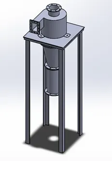
Case 1: Cyclone Separator without metallic stiffener.
- A model of Cyclone separator.
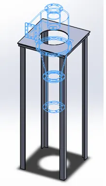
2. Excluding Cyclone saperator parts to perform analysis on the long Stand legs.
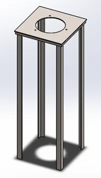
3. Material applied is Alloy steel.
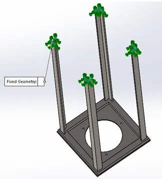
4. Fixing the Legs by adding fixtures.
4. Applying a Load of 150kN to the top face.
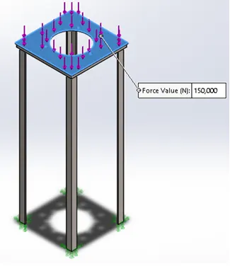
6. Generating Fine Mesh.
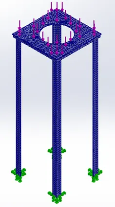
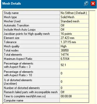
7. Running the study for analysis.
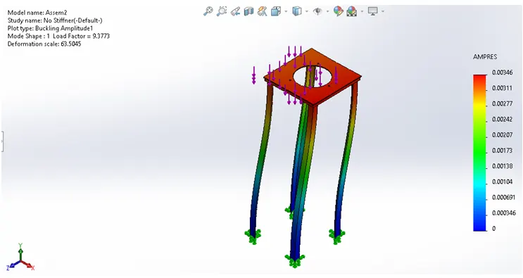
8. Observation.
- The Result shows how the model will behave under applied loding condition.
- The Rectangular Color Coded bar on the righ dipicts the resultant amplitude. Which varies from 0 to 0.00346mm.
- The bottom most part or the fixed part of the stand shows little or no deflection. But as we move up the sway or amplitude of deflection increases and eventually attains it’s peak value.
- Buckling factor of safety is 9.37.
Case 2: Cyclone Separator with metallic stiffener.
To limit the deflection of the stand under applied loading condition we will use stiffener.
- Creating a Rectangular stiffener by extruding the sketch 75mm.
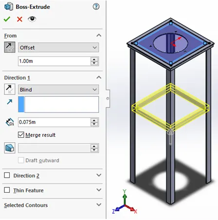
2. Apply the material as Steel alloy.
3. Apply the Fixture at the bottom face of the leg.
4. Apply a load of 150kN at the top face of the stand.
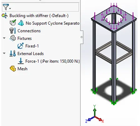
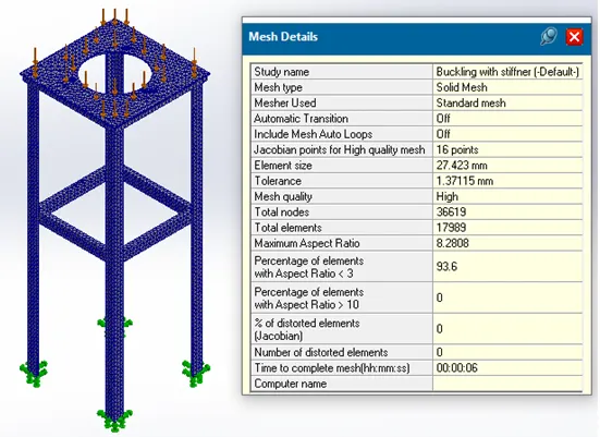
5. Creating fine mesh.
6. Results after running the study.
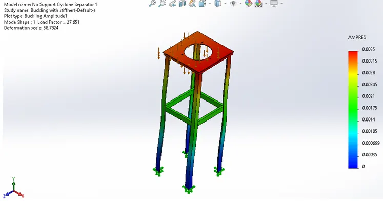
7. Observation.
- By adding a Stiffner Buckling Factor of safety have increased up to 27.651.
Design Optimisation:
Case 1: Performing Design optimization study, by varying the position of 75mm thick stiffener along the length of the stand.
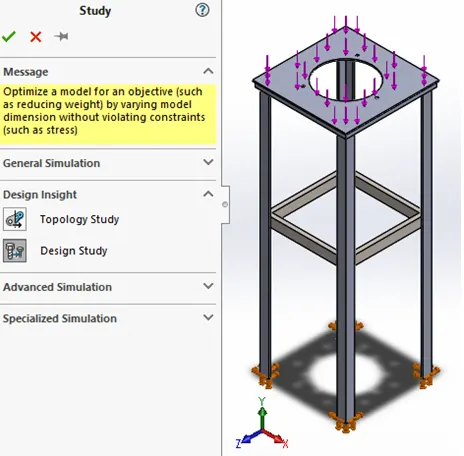
- Varying the position of the stiffener along its length to obtain the maximum Buckling factor of safety.
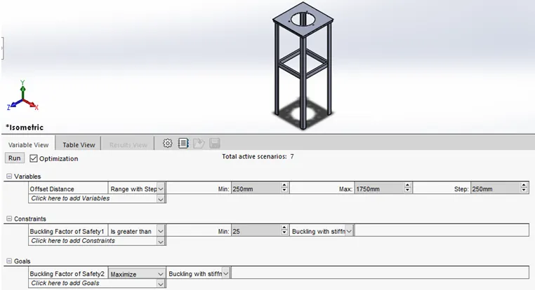
2. Results.
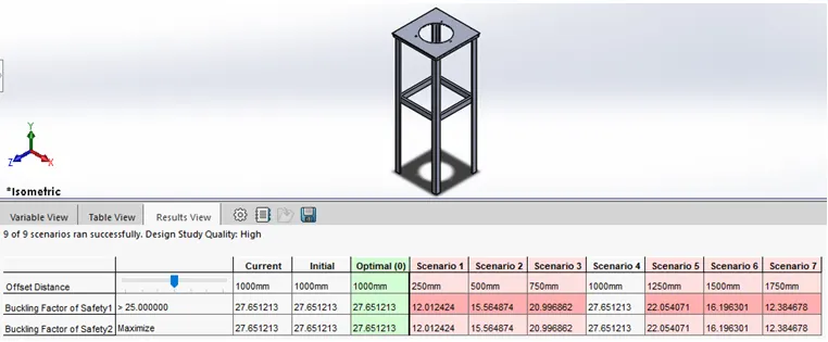
3. Observation.
- The maximum Buckling Factor of safety is achieved in Scenario 4, when the stiffener is positioned at a distance of 1000mm from the top face of the stand.
- Buckling Factor of safety reduces, as we position the stiffner upwards and downward. And the value reduces nearly upto 12 at the topmost and bottomost part position.
Case 2: Performing Design optimization study, by varying the position of the stiffener along the length of the stand and also varying the thickness of the stiffener (from 75mm to 125mm).
- Results.
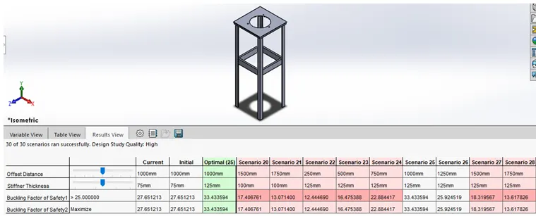
2. Observation:
- There are two scenarios (i.e. 25 & 26) when Buckling factor of safety is greater than 25.
- Maximum Buckling factor of safety of 33.43, is achieved when the stiffener is positioned 1000mm away from the top with maximum thickness of the stiffener being 125mm.
- With increase in stiffener thickness the Buckling factor of safety increases.
- To minimise the weight of the stand the thickness of the stiffener could be constrained, as we are getting feasible values of Buckling factor of safety for lower thickness values too.