Boeing-747 _ Final_Project of Boeing
Boeing-747 _ Final_Project of Boeing
OBJECTIVE:
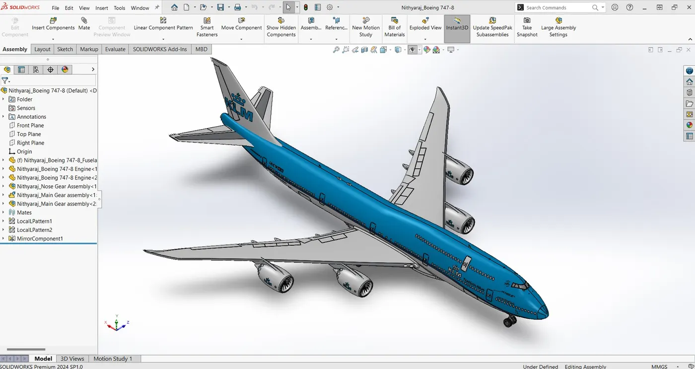
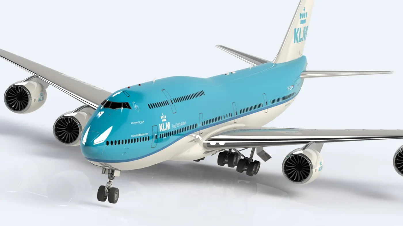
Creating a boeing-747 full body structure using the 2D sketch entities and 3D feature and assemble the all parts with realistic rendering.
INTRODUCTION:
The Boeing - 747 is a large and long range Wide-body airliner designed and manufacturated by Boeing commercial Airplanes in the United States between 1968 and 2023.
The Boeing-747 is a four engined aircraft. It typically accommodates 366 passengers in three travel classes. It has a pronounced 37.5 degree wing sweep and its heavy weight is supported by four main landing gear legs,each with a four - wheel bogie.
DESCRIPTION:
BOEING - 747 PARTS
- Blueprints
- Fuselage
- Belly fairing
- Nose Cone
- Pitot Tubes
- Cockpit window
- Passengers Window
- Door & Hatches
- Light & Antenna
- Auxiliary Power Unit
- Vertical and horizontal stabilizer
- Wing Flap & aileron
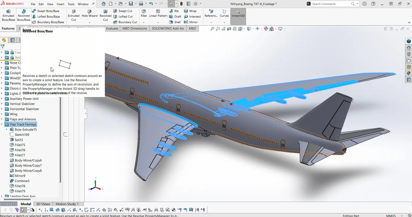
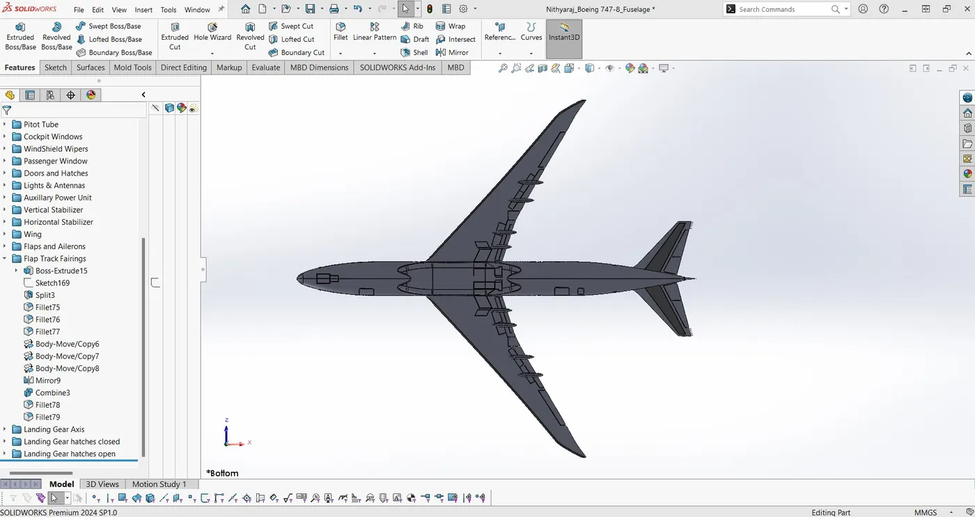
- Flap Track fairing
- Landing gear hatches
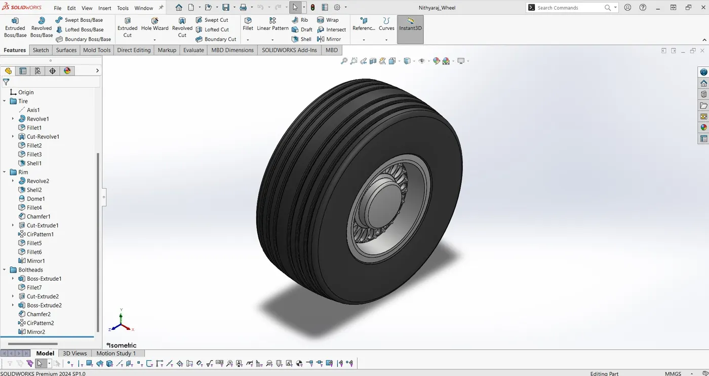
- Wheel
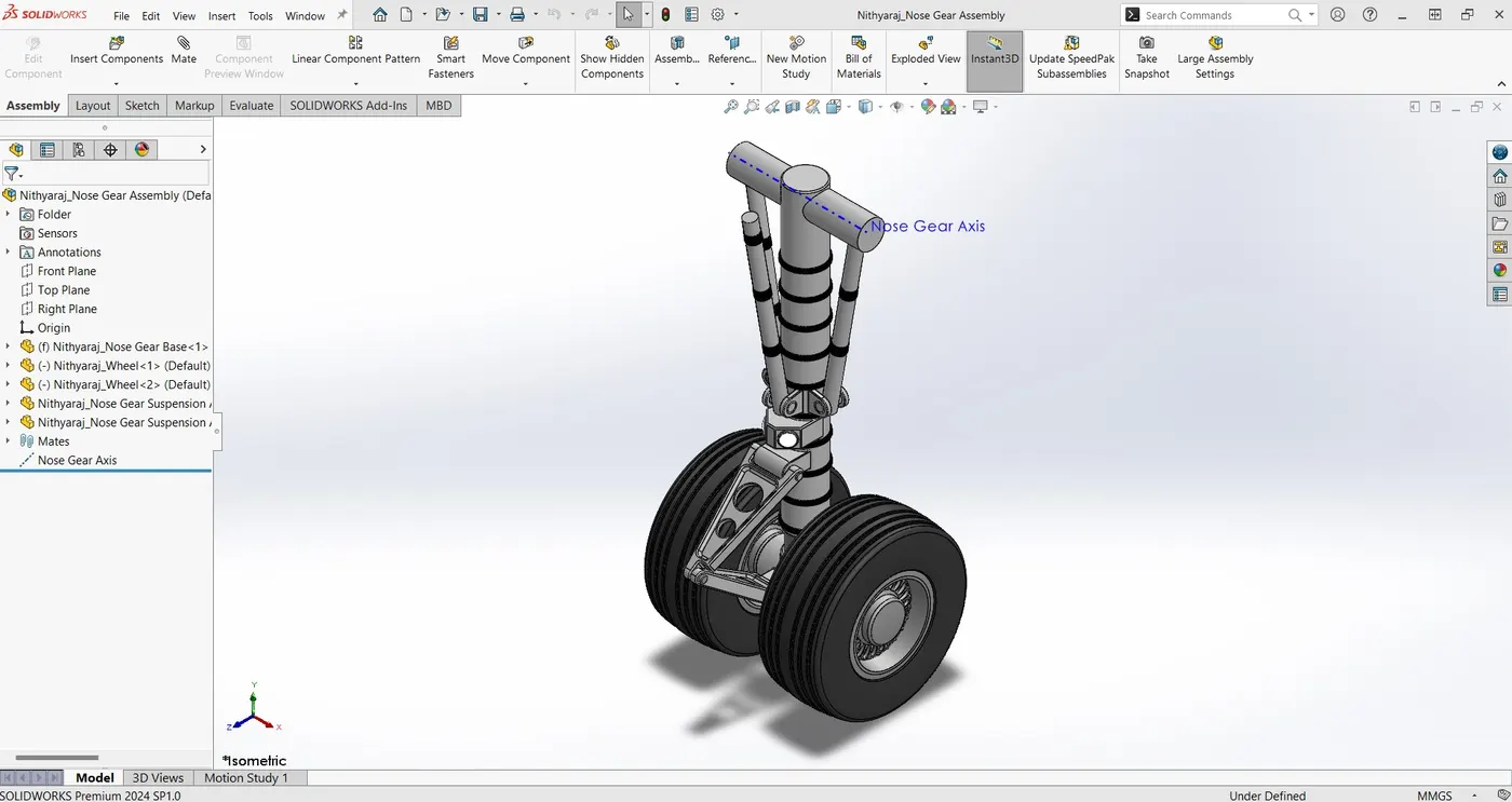
- Nose Gear
- Main Gear
- Engine
TOOLS:
SKETCH TOOLS - LINE, CIRCLE , SPLINE, 3-POINT ARC, CENTER RECTANGLE , CORNER RECTANGLE , FILLET,CHAMFER, MIRROR, LINEAR SKETCH PATTERN, CIRCULAR SKETCH PATTERN, CONVERT ENTITIES , OFFSET ENTITIES,TRIM , SMART DIEMENSION , SPLIT LINE , AXIS , PROJECT CURVES , PLANES .
FEATURES - EXTRUDED BASS\BOSE , REVOLVED BOSS \ BASE , EXTRUDED CUT , REFERENCE PLANE , LINEAR PATTERN , CIRCULAR PATTERN ,MIRROR , FILLET , CHAMFER .
1. BLUEPRINTS:
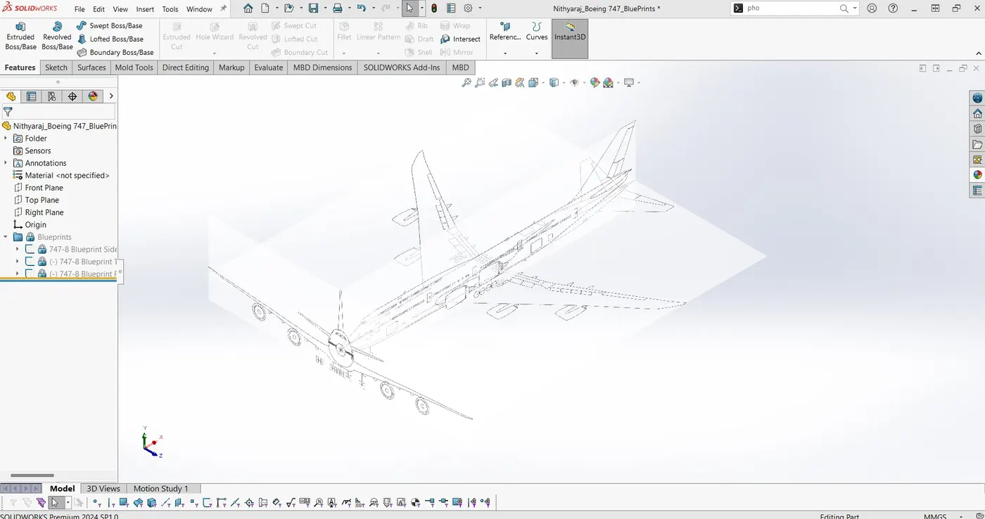
A blueprint is a reproduction of a technical drawing or engineering drawing using a contact print process on light sensitive sheets.
2. FUSELAGE:
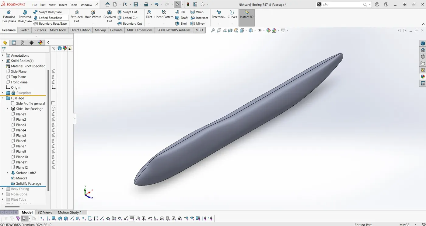
A fuselage is essentially the body on an aircraft or specifically ,the large outer that encompasses the aircraft main body .The fuselage is core aspect of the aircraft and serves many purposes
3. BELLY FAIRING:
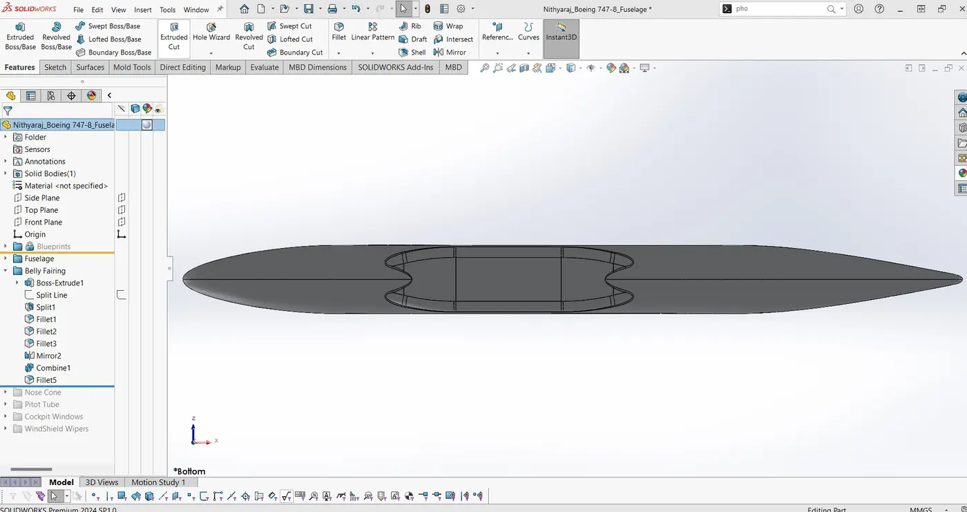
Belly fairing Also called a "ventral fairing", it is located on the underside of the fuselagebetween the main wings. It can also cover additional cargo storage or fuel tanks. Cockpit fairing Also called a "cockpit pod".it protects the crew on ultralight trikes.
4. NOSE CONE:
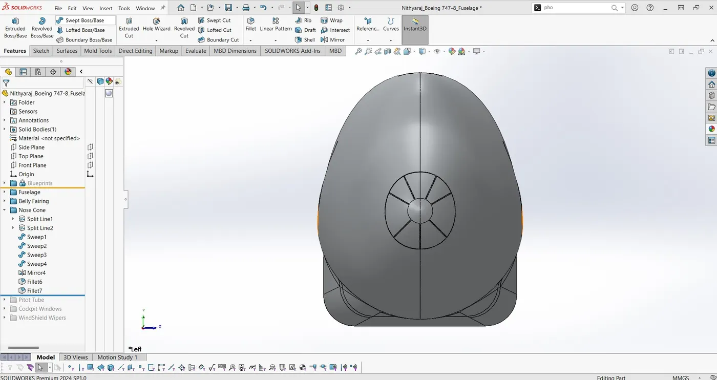
The nose cone is the most forward fuselage piece . A nose cone is the conically shaped forwardmost section of a rocket, guided missile or aircraft, designed to modulate oncoming airflow behaviors and minimize aerodynamic drag.
5. PITOT TUBES:
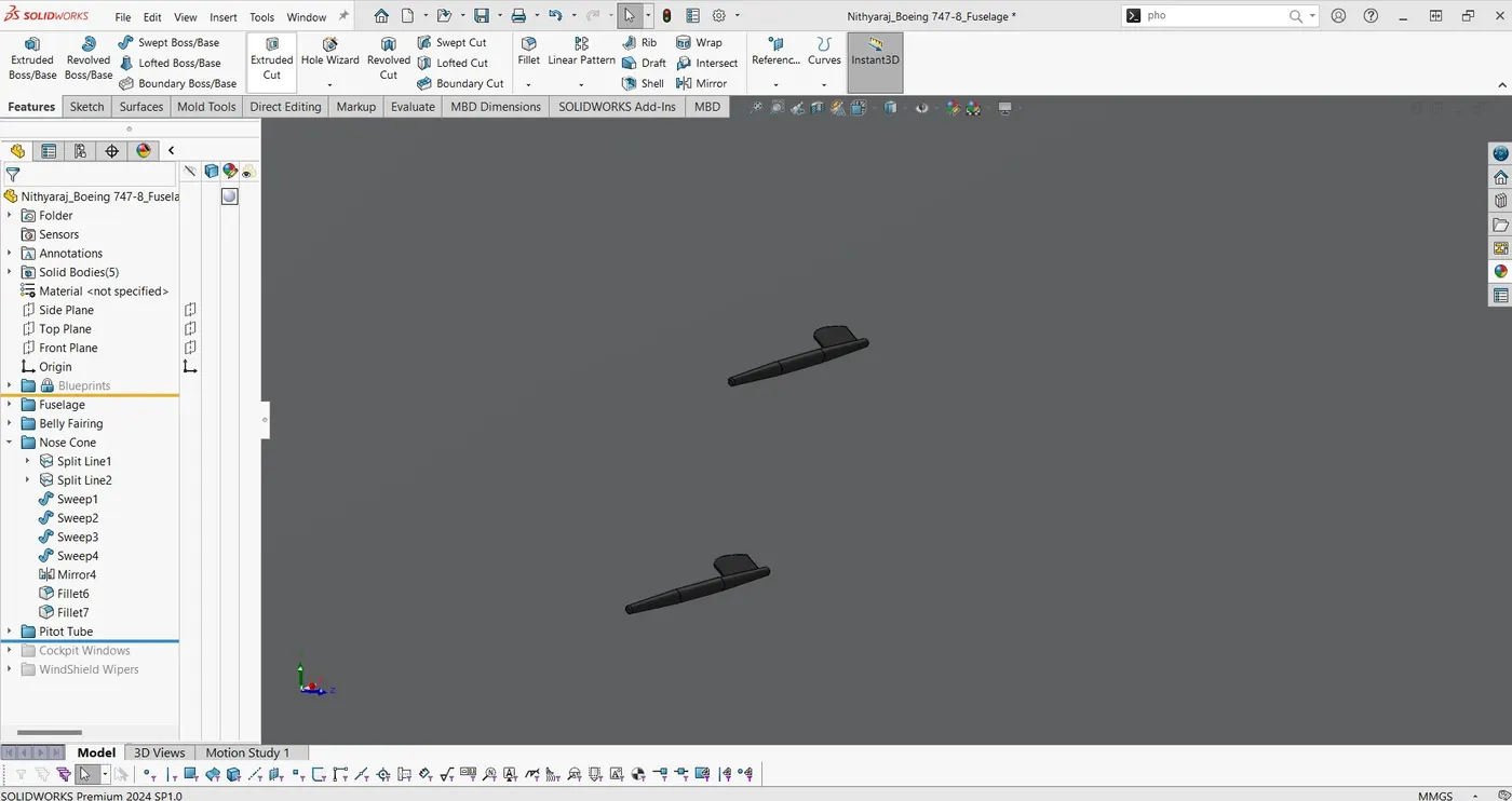
Pitot tubes is created using fuselage sketch with a given dimensions for design. 4 Pitot tubes are created for given aircraft. Pitot tube is also known as Pitot probe is a device used for flow measurement used to measure flow velocity.
6. COCKPIT WINDOWS:
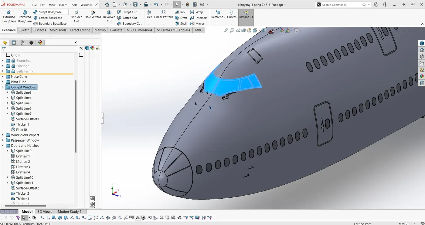
The main thing to know is that aircraft cabin windows are not made of glass, but with something called "stretched acrylic". It's a lightweight material manufactured by a few global suppliers for the various aircraft flying today.
7. PASSENGER WINDOW:
8. DOOR AND HATCHES:
9. LIGHTS AND ANTENNA:
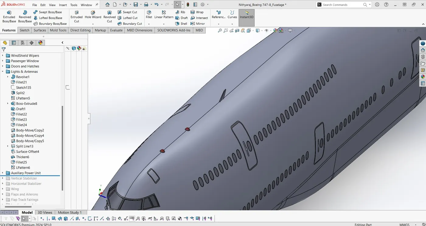
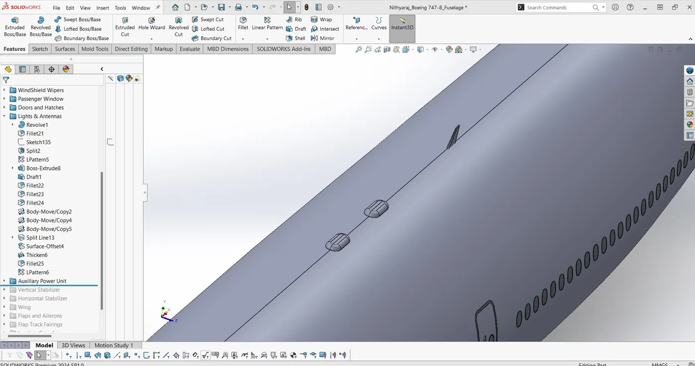
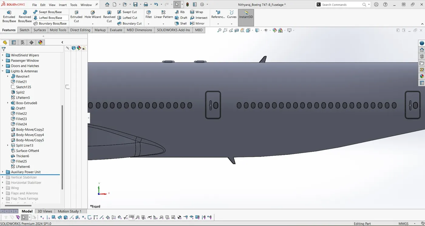
The red and green lights found on the wingtips of airplanes are known as navigation lights.They are designed to increase the airplane's visibility to other pilots, as well as air traffic controllers on the ground, to minimize the risk of collision. Navigation lights don't emit any signals.The antenna at the transmitter generates the radio wave.
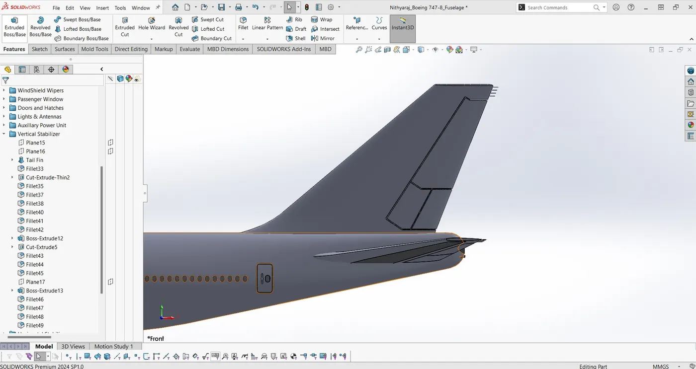
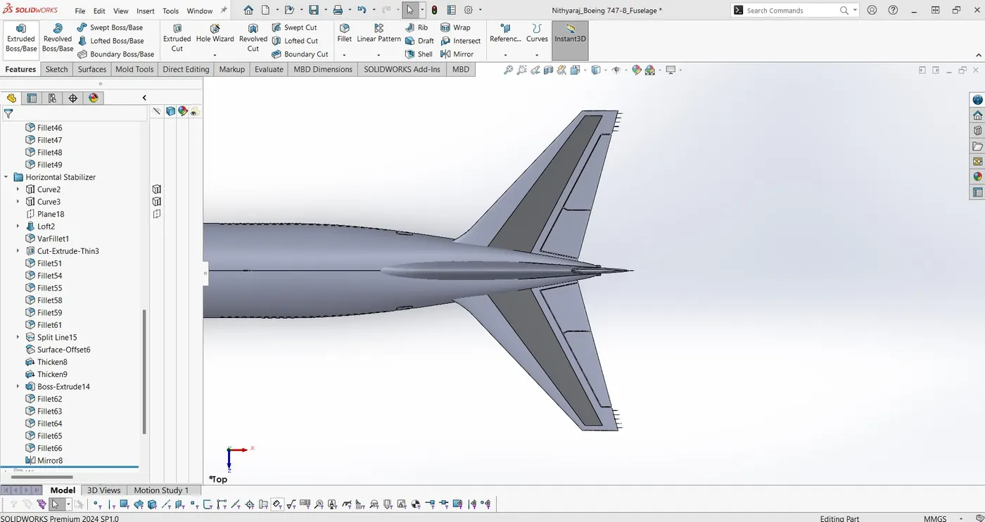
10. VERTICAL AND HORIZONTAL STABILIZER:
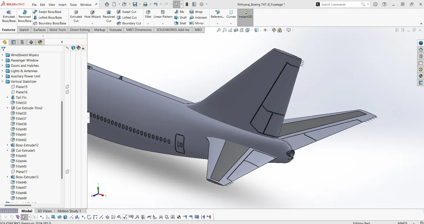
The vertical stabilizer keeps the nose of the plane from swinging from side to side, which is called yaw. The horizontal stabilizer prevents an up-and-down motion of the nose, which is called pitch.
11. AUXILLARY POWER UNIT:
12. WINGS, FLAG AND AILERON:
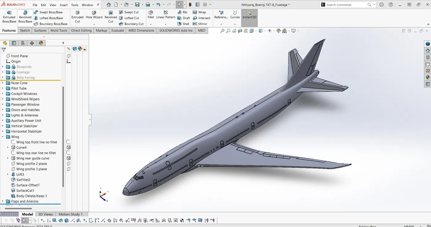
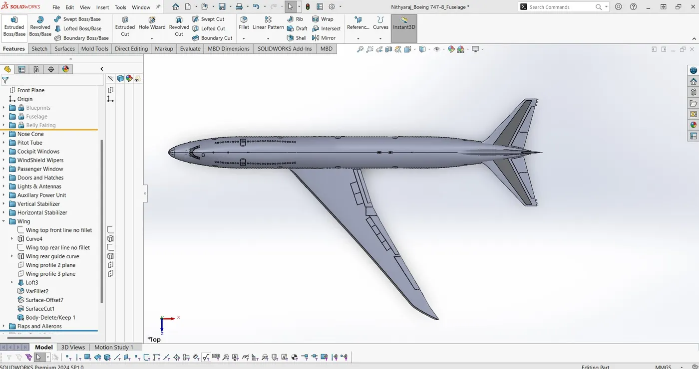
A wing is a type of fin that produces lift while moving through air or some other fluid. Accordingly, wings have streamlined cross sections that are subject to aerodynamic forces and act as airfolis. A wing's aerodynamic efficiency is expressed as its lift to drag ratio. The lift a wing generates at a given speed and angle of attack can be one to two orders og magnitude greater than the total drag on the wing.
13. FLAP TRACK FAIRING :
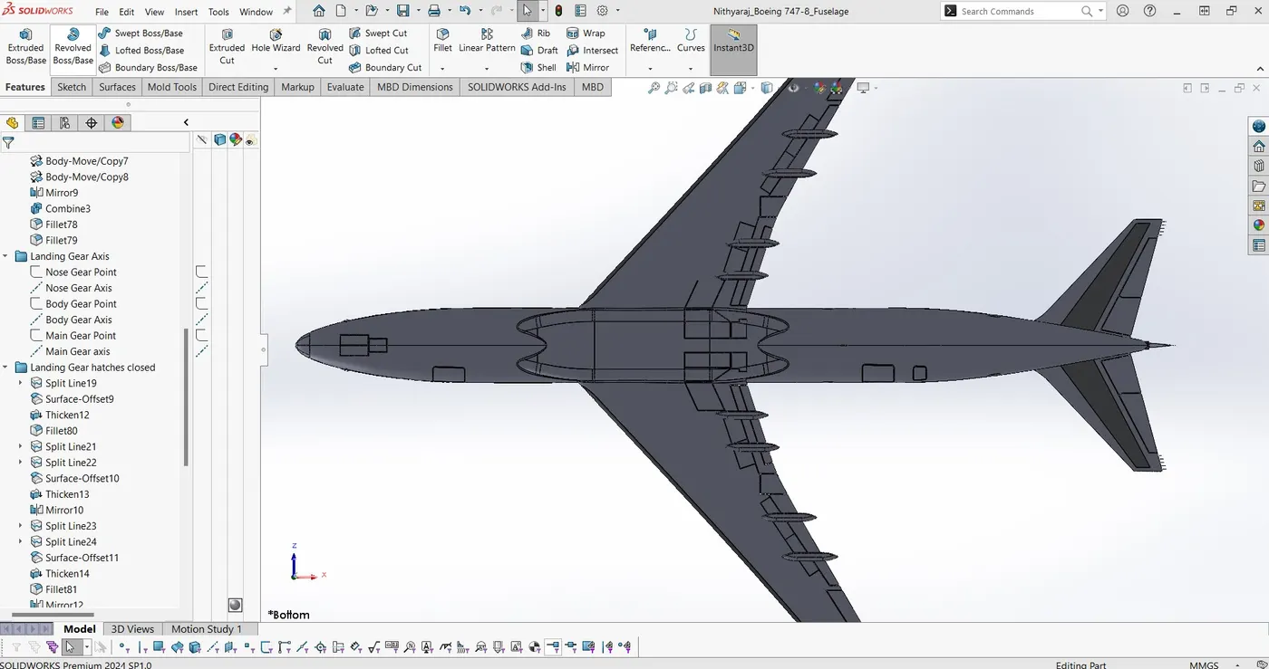
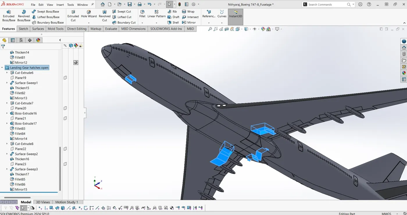
14. LANDING GEAR HATCHES CLOSE AND OPEN:
15. WHEEL:
16. NOSE GEAR:
17. MAIN GEAR:
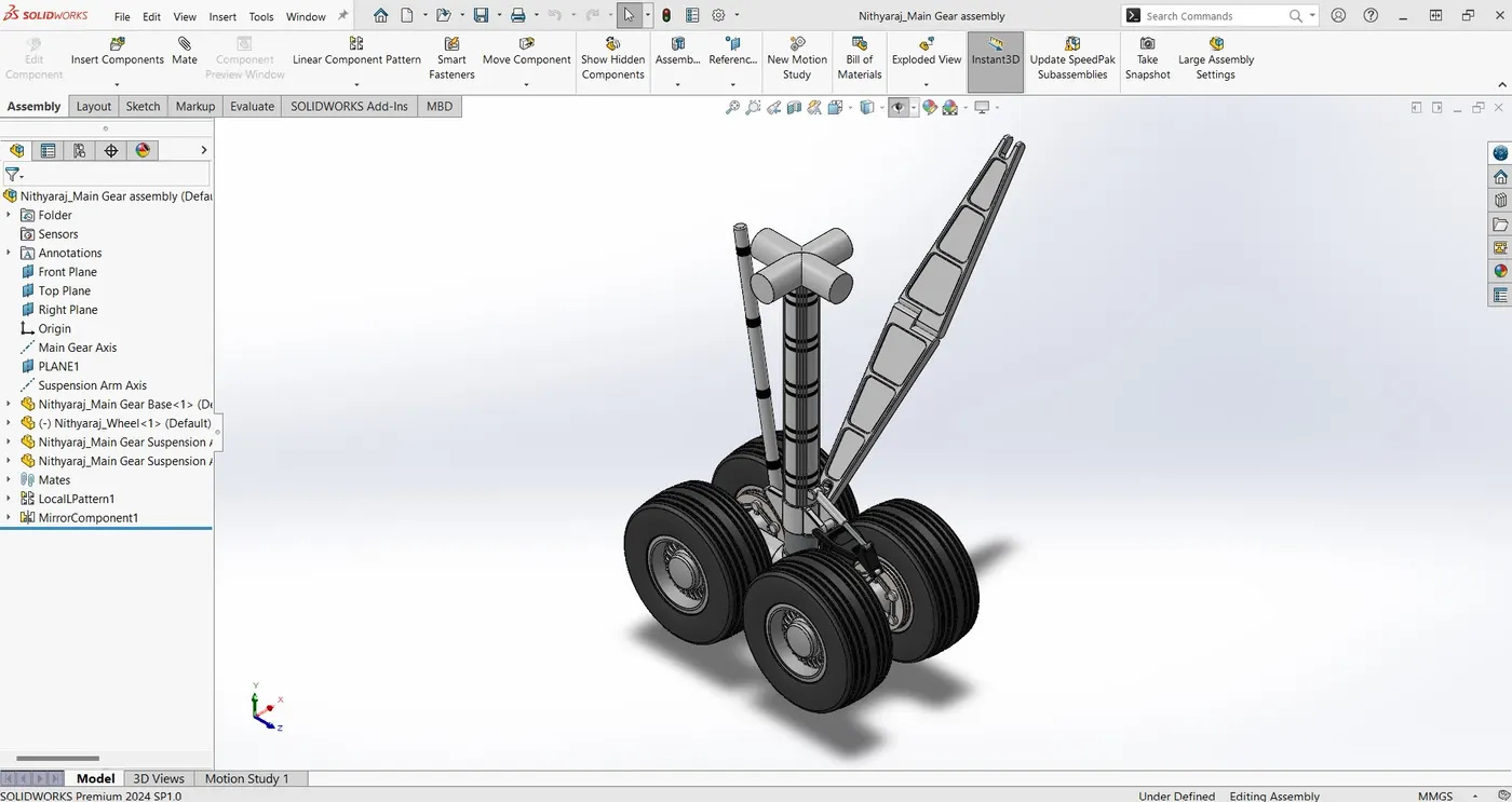
18. ENGINE:
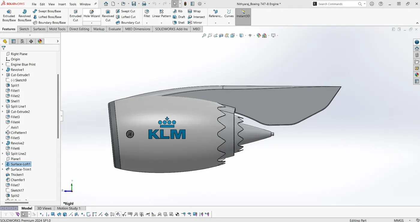
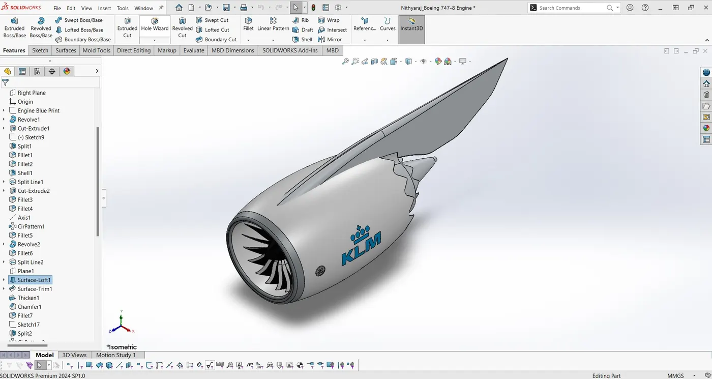
MAIN ASSEMBLY:
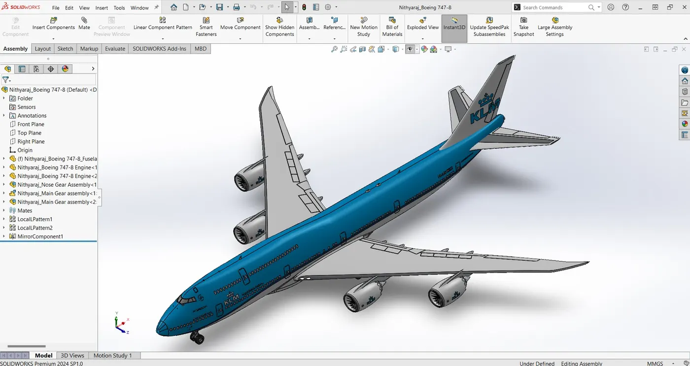
RENDERING IMAGE:
CONCLUSION:
In this project the various parts of the boeing 747-8 was modeled with the different environments surface modeleing, solid modeleing and assembly availabile in the solidworks.
Please find the CAD files below Link
Google Drive Link: https://drive.google.com/file/d/1Jor0MdfdgBThN3wAnv1vtrmDPKxlpCOf/view?usp=sharing