Bird Strike - Project - 2
Aim :
Explanation:
Introduction to Bird strike simulation and its significance
Bird strikes are a major threat to aircraft structures, as a collision with a bird during flight can lead to serious structural damage. Computational methods have been used for more than 30 years for the bird-proof design of such structures, being an efficient tool compared to the expensive physical certification tests with real birds. The regulation requires all gas turbine engines and particularly turbofan engines must be durable in order to withstand ingested birds.
A bird strike is classified as a high-velocity soft body impact because the stresses, which are generated in the contact region, are significantly greater than the strength of the bird but lower than the strength of the impacted structure. High deformability of the impactor (bird) causes spreading of the impact load over a certain area of the structure that requires the use of special strain-rate-dependent material models.
Most numerical analyses employ one or more of the following techniques; Lagrangian, Eulerian, arbitrary Lagrangian Eulerian (ALE), and smooth particle hydrodynamics (SPH). The work carried out here is on basis on Lagrangian approach using solid and shell elements using the conventional Finite element method.
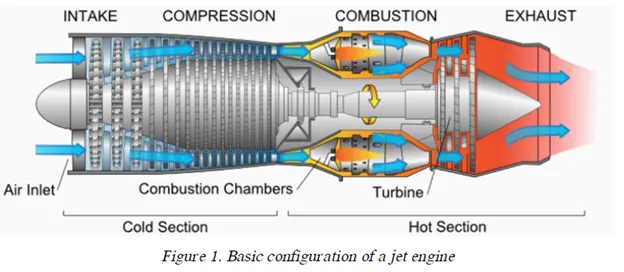
The basic configuration of jet engines is composed of an air intake, a compressor or a fan, a combustor or a combustion chamber, a turbine and an exhaust nozzle. Thereafter, aerodynamic design technology for a compressor and a turbine, cooling technology for turbine blades.
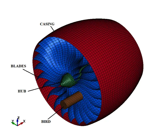
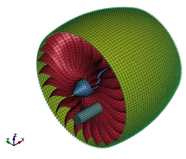
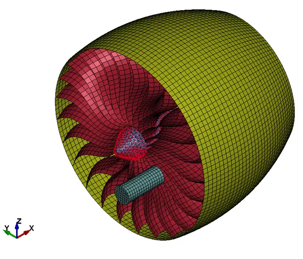
The area of interest in this analysis consists of a hub with fan blades attached to it, rotating at certain speed (around 5000rpm) enclosed in a casing. A bird travelling at a speed as mentioned in regulations (75 m/s) impacts the blades. The material properties of casing, hub, blades and bird are provided. The load case is setup accordingly to study the impact and determine the stability of the assembly upon impact.
PRE-PROCESSING :
(1) Discretization :
The input file provided for the simulation consists of the assembled Finite element model.
The components of the assembly are casing, hub, blades and the bird. Node s and the corresponding elements are numbered as per the convenience.
(2) Section properties :
Hub is meshed with solid elements, casing, blade and bird components are meshed with shell elements.
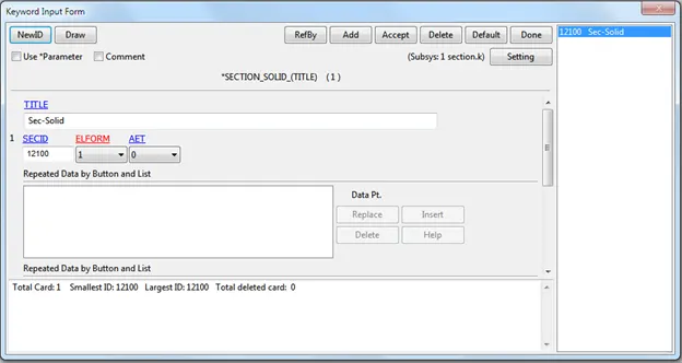
Solid element formulation (ELFORM = 1) is used for the hub.
Thickness of the blade is a cumbersome process to arrive as it varies from leading edge to trailing edge and along the length of the blade. An average value of 8 mm is used as approximation.
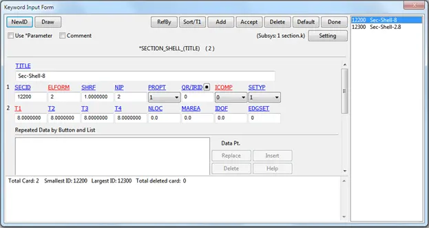
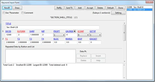
Shell elform=1 is used for the shell elements. Two shell section keywords are used to specify the thickness of the blades(t=8) and the bird(t=2.8).
(3) Material properties :
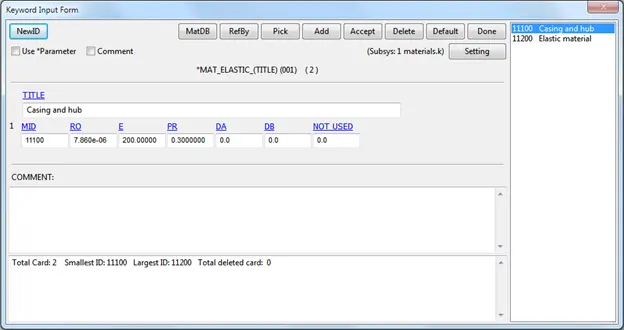
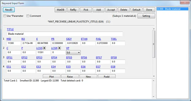
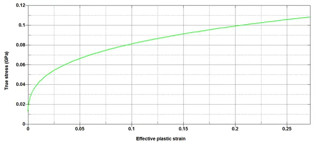
Casing part is modelled with an elastic material with Young's modulus 200 GPa. The hub is assumed to be made of same material as the casing. Blade is modelled as elasto-plastic material with the given true stress- effective plastic strain provided with material card.
Accordingly, a MAT_01 Elastic card is created for casing and hub with the following properties.
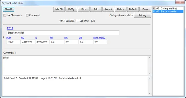
A MAT_01 Elastic card is created for bird material with the following properties
And MAT_24 Piecewise linear plasticity card is created for the blades.
The curve of effective true stress vs effective plastic strain is added beyond the yield point.
(3) Boundary conditions/Constraints/Loads:
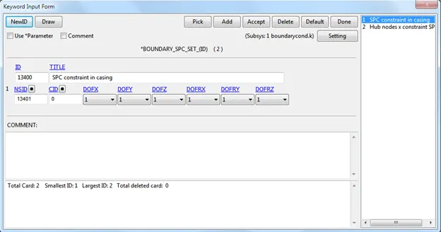
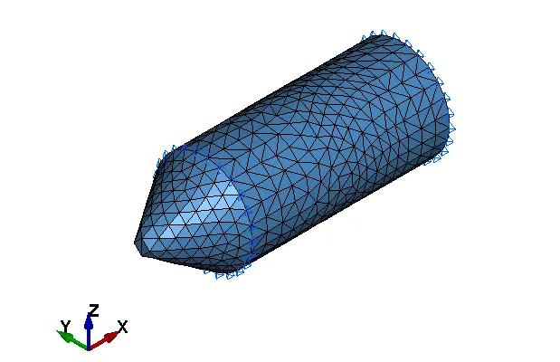
1. The casing nodes are fixed in all degrees of freedom. A nodeset id is created and a SPC constraint keyword is used.
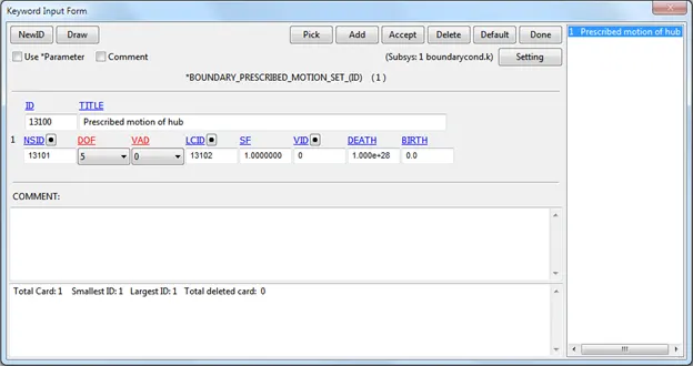
2. The hub is rotating at constant speed driven by the output shaft through engine. The hub is assumed to run at 5000 rpm (during cruise). A prescribed motion set keyword with VAD =0 and =5 (x rotational dof)is used to impart the constant rotational speed. A curve is defined to apply the constraint throughout the simulation. This is because, even if the blades are hit or deformed during flight, the output shaft rotates at constant speed.
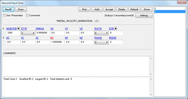
3. The blade is attached with hub also rotates at the same speed as the hub. An initial velocity generation keyword is defined for the blades by specifying the rotational speed(omega) along the rotational axis(x direction).
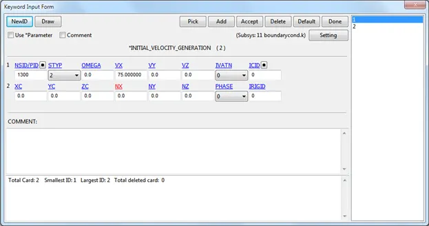
4. The bird is assumed to travel axially (along x direction) at a speed of 75 m/s as required by the testing standards. Another initial velocity generation keyword is created with above mentioned parameters.
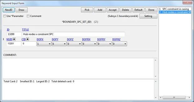
5. Since the hub is rotating at constant speed driven by the main shaft, the nodes of the hub on the rear side is constrained to move along that direction (x direction). Hence, a SPC_SET keyword is used for this purpose. The nodes selected for this constraint is specified using nodeset id
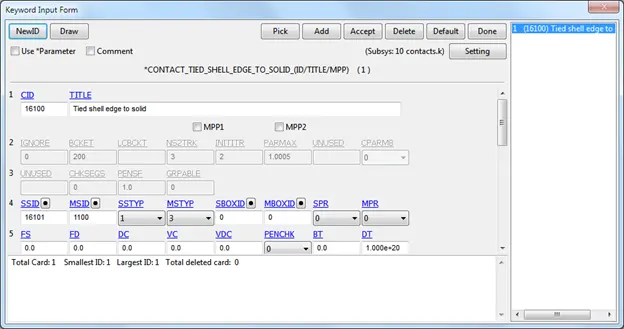
6. A tied_shell_edge_to_solid keyword card is used to tie the blades on to the hub to prevent any relative movement between the components. Accordingly, a shell element set is defined as slave and the solid hub part is designated as the master.
(4) Contact :
To study the contact interaction among the various components, following contact keyword cards are used.
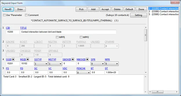
1. Blade and bird: An Automatic_surface_to_surface keyword is used. Blade is designated as master and bird as slave based on their stiffness
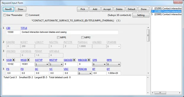
2. Blade and casing: An Automatic_surface_to_surface similar to above is used to study the interaction between these parts. The casing is designated as master and blades are designated as slave on the basis of the stiffness
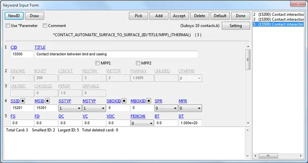
3. Casing and bird: An Automatic_surface_to_surface is used here too with the casing designated as master and bird designated as slave. This may be required so as to study any interaction is seen after impact of bird on the blades.
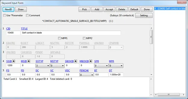
4. Self contact in blade: To study contact interaction in blades upon impact, an Automatic_single_surface keyword is used with slave as blade.
(5) Control :
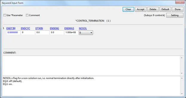
Control termination keyword is added with endtime = 8 ms.
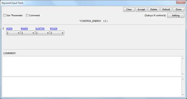
To calculate the hourglass energy, and sliding energy, Energy keyword card is activated.
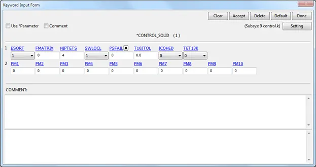
Control_solid keyword is added with ESORT=1 is used to avoid degenerate formulations for these shapes.
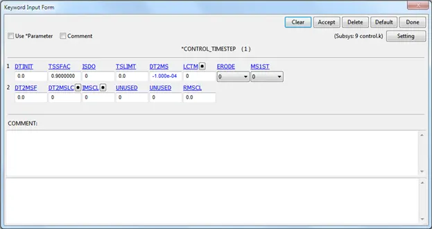
Mass scaling is activated to accelerate the solving process. The mass scaling factor was optimised to arrive at a value of -2e-4 for the given configuration(component setting).
(6) Database :
Binary d3plot keyword is created to notify the solver to output the result at every 0.1 ms of the end time.
Extent_binary keyword with strflg flagged to 1 to record the strain for every de3plot.
The following ASCII files were requested to verify/analyse for the post processing of the simulation.
Glstat, matsum to study the energies.
Nodout for analysing the acceleration plots and eleout for analysing the stress strain plots.
(7) Include:
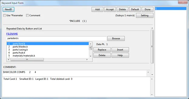
Separate keyword files were added in the main file using the Include keyword. This makes the work convenient during the solver as the error occurred if any during the run can be checked by tracking the part_id, nodeset_id, or any corresponding keyword card. The keywords were saved in different folders and included in the main file.
SOLVING :
The above created input file is saved as keyword file (.k extension). This keyword file is solved using LS DYNA manager.
POST PROCESSING :
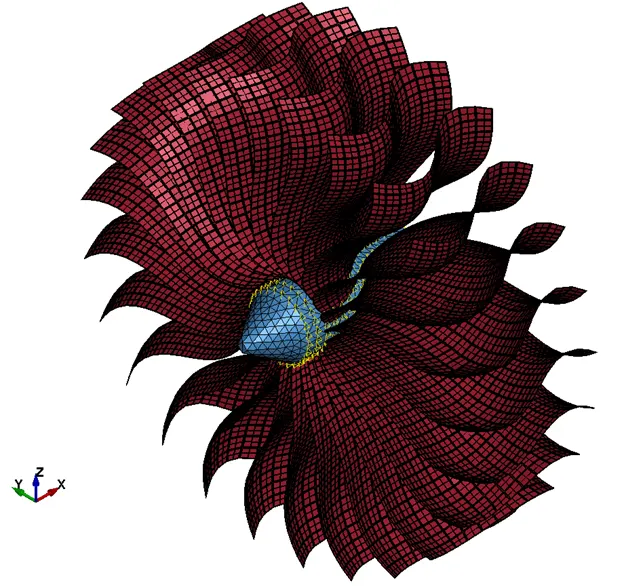
Various contour plots are plotted to check for sanity of the problem being solved. The animated file of the problem can be checked by running the d3plot file in the LS-PrePost.
Animation plots:
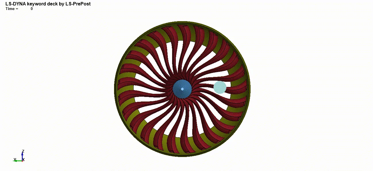
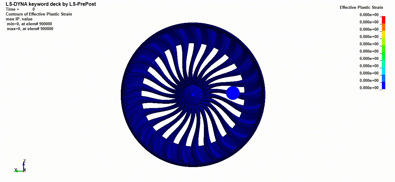
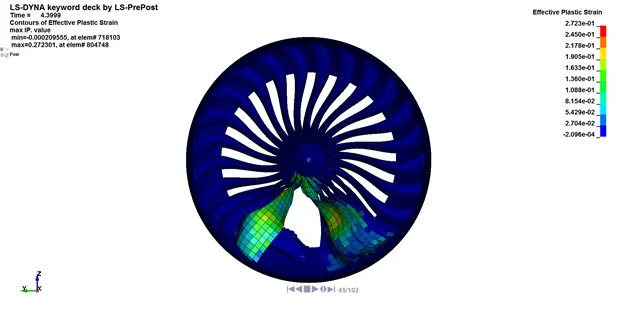
Von-Mises stress Effective plastic strain
Verification: The performed analysis can be verified by drawing a plot energies.
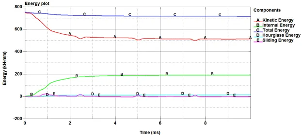
The total energy remains constant throughout. Hence, it can be inferred that total energy is conserved and simulation carried out is sound. There is an increase in hourglass energy due to distortion of shell elements of the bird as well as blade. Further this can be taken into consideration by using Control_hourglass keyword for changing the co-efficient.
Von mises stress
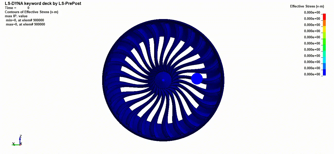
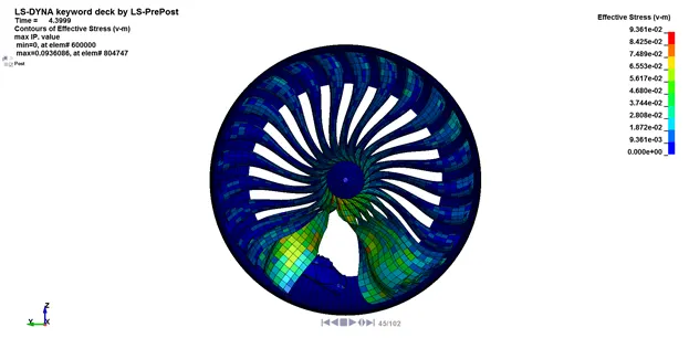
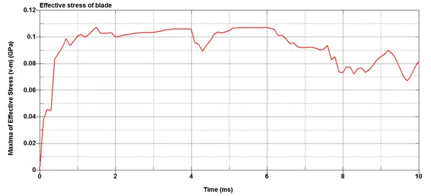
The value of effective stress on the blade peaks to 0.108 GPa, with the blades deformed due to impact.
Effective plastic strain(blades)
Conclusion:
The bird strike simulation was carried out by using Lagrangian approach with the the help of solid and shell elements using explicit methods. The meshed model provided was to build the load case with the given material card and assuming speed of the bird and the hub velocity, the contacts were defined to study the interaction among various parts. Stress and strain plots were drawn to find the critical part of the assembly. The simulation performed here can be used as an initial step to include the complexities of the thickness function of the blades. Further studies can be conducted by varying the position of the bird and varying its approach velocity.
Please follow the link to access the input, output and animation files: https://drive.google.com/drive/folders/1IT1tcOLh7Wt_-OTAcxDZ7TMii-WbprrO?usp=sharing
Appendix 1:
| Issues | Debugs |
| Non-uniform velocity/rotation seen during initial run | Deletion of unreferenced nodes |
| Displacement of hub after impact | Nodes on the front side of hub constrained to restrict this movement |
| Solid element was ten node format | CONTROL_SOLID, ESORT toggled to 1 |
Appendix 2:
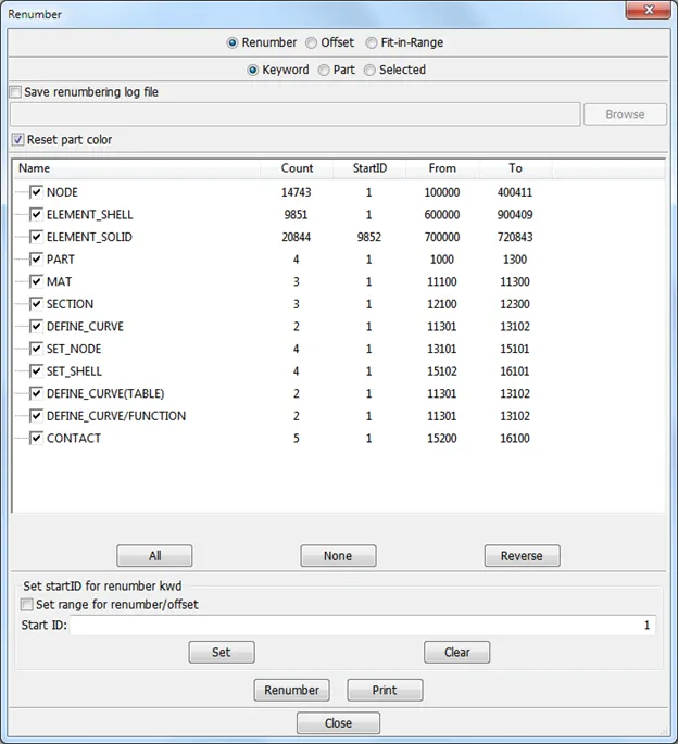
This short summary of the parts, nodes, elements numbering along with the identifier serial numbers used for different keyword cards.