Week - 3 Drop test Challenge
Aim : To create the input file to simulate the cellphone drop test.
Explanation:
Physics :
Understanding the problem and isolating the system: The cellphone is dropped from, at some distance vertically in the downward direction with some intial velocity.
Deciding system under consideration (mobile phone being dropped) : Since the cellphone is the subject under study, the cellphone is treated as deformable body and the floor is treated as a rigid body.
Assumption : Both the cellphone and the floor is assumed to be of same material.
PRE-PROCESSING :
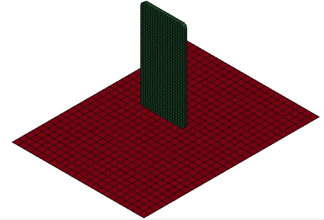
(1) Discretization : The meshed file containing nodes and elements is provided. The file is imported into the LS-PrePost environment.
(2) Section properties :
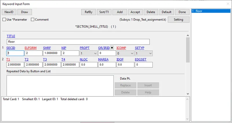
The section properties for the floor is selected as Shell elements with element formulation ELFORM 2, and thickness is given as 2mm. The number of integration points is selected as 2.
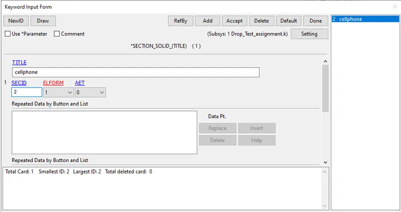
The cellphone is made up of 3D brick elements, and default element formulation of constant stress solid element is selected.
(3) Material properties :
The material properties for rigid-shell elements and deformable-solid element are as follows. The values entered here are arbitary, as the properties have not been specified.
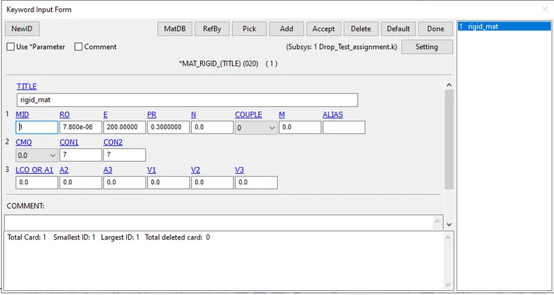
For rigid floor :
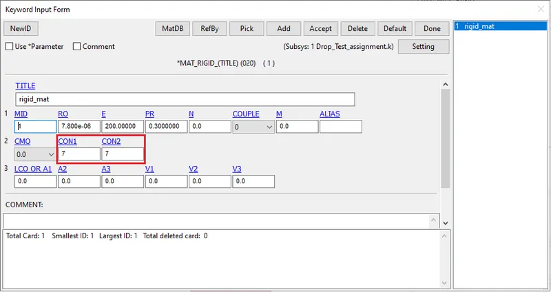
MAT_20 RIGID
Density : 7.800e-06 units
Young's modulus : 200 units
Poisson's ratio : 0.3
Deformable cellphone:
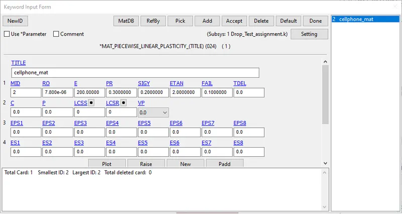
MATERIAL PIECEWISE LINEAR PLASTICTY (MAT_24) card is defined which enables to study the impact during the drop as the stress values goes beyond the elastic limit.
Density : 7.800e-06 units
Young's modulus : 200 units
Poisson's ratio : 0.3
Yield stress : 0.20 units
Tangent modulus : 2.00
Failure flag : 0.10 (Plastic strain to failure. When the plastic strain reaches this value, the element is deleted from the calculation.)
(3) Boundary conditions/Constraints/Loads :
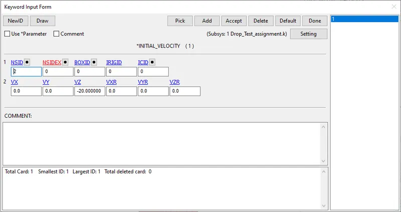
Initial velocity: Since the cellphone is being dropped with some velocity, the intial velocity is defined for all the nodes of the deformable body by creating node set ID. A value of 20 units is give in negative Z direction.
Constraint:
The floor is rigid and the constraint is already defined in the material card.
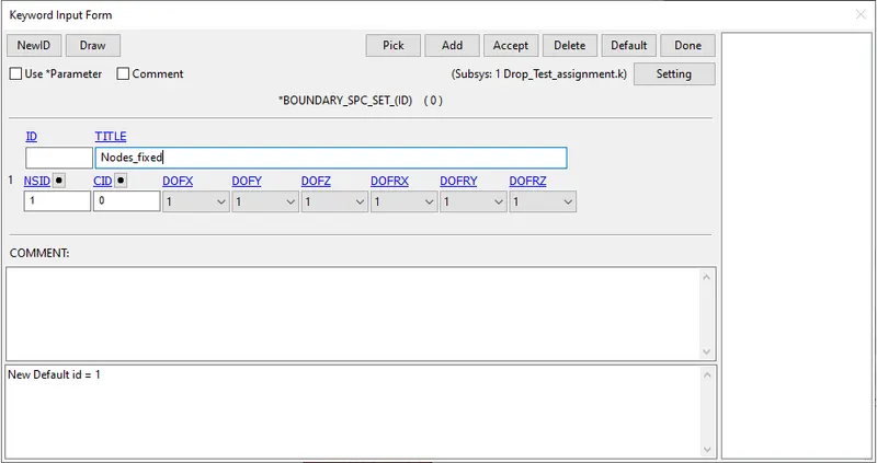
Since the floor is fixed, the constraint can be defined in the material card itself. The CON1 representing the translational dispacements is selected as 7 which denotes contrained in all three (x, y, z directions) and CON7 representing rotations which is selected as 7 which constraints in all three rotational degree of freedom. In addition, all the nodes of the part are fixed using SPC_SET and constraining in all degrees of freedom.
(4) Contact :
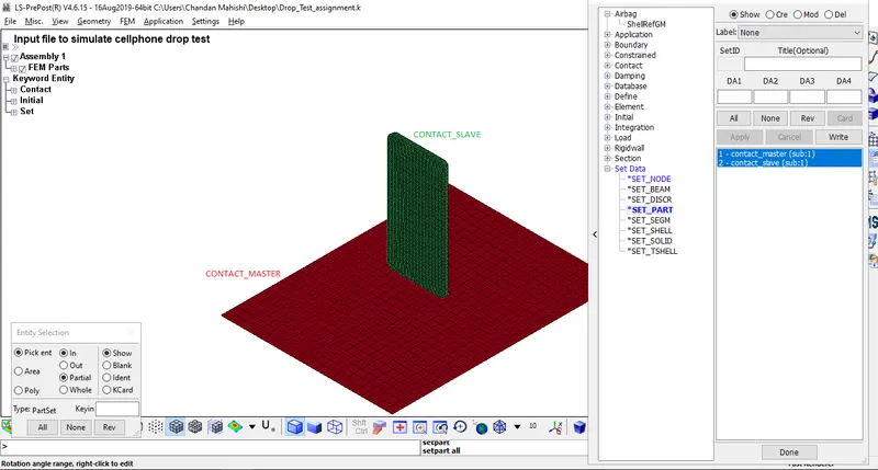
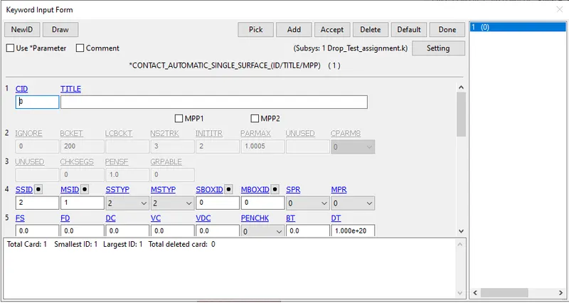
An automatic single surface contact is defined to study the impact of cellphone dropped on the floor. Master and slave components in the form of segment set, node set, part set or shell element ID are to be selected and their type have to be accordingly selected. In this case the part set ID for both Master (Rigid floor) and Slave (Cellphone) is created using *SET_PART under Create entity tab.
(5) Control :
Under control, the termination card is defined for specifying the end time/termination time. End time for this case is entered as 10 units.
(6) Database :
Binary D3Plot is written for every 1 unit interval of time.
ASCII files and binary files of Global Statistics, Material energies, Sliding Interface energies are requested to written for every 0.1 unit time to study the different energies during the impact.
(7) Part :
In this section, the different parts/components in the file are connected to their respective material ID and section ID.
Once all the above is done, Model check is done to ensure all the parts are connected to their respective material, section and various components in contact/to be in contact are all well defined. A dialog box containing the cards - the errors, warnings, unreferenced, undefined are displayed. Approppriate action should be taken to overcome errors and warnings can be minimised.
SOLVING :
The above created input file is saved as keyword file (.k extension). This keyword file is solved using LS DYNA manager.
POST PROCESSING :
Various contour plots are plotted to check for sanity of the problem being solved. The animated file of the problem can be checked by running the d3plot file in the LS-PrePost.
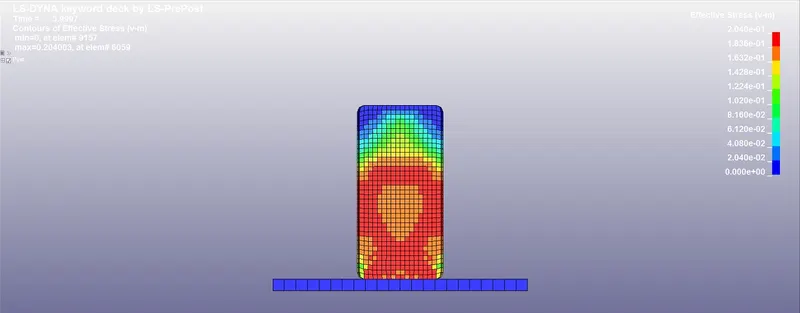
Stresses along a particular direction, Von Mises stress can be checked from the "fringe" tab. As seen from the graph, the base of the cellphone is the most stressed part when the Von Mises stresses are requested for. Various plots of stress, deflection can be plotted from the fringe tab and requested to be written for "dt" time interval.
Please follow the link for accessing the input mesh files and the setup file for drop test: https://drive.google.com/drive/folders/1phJJl_FVjOEQKzwT1BtavYhOAeVqBv9P?usp=sharing