Week - 5 - Modelling Spotwelds
Aim : To model spotwelds for the given assembly of parts and run a crash test.
Explanation:
Physics :
The spotwelds in Finite element analysis can be modelled as i) beam element ii) solid element with different element formulation. In the current test scenario the plates are spot weld at six points in transverse direction and moving at a speed of 50 kmph crashing into a rigidwall.
PRE-PROCESSING :
(1) Discretization : The meshed file containing nodes and elements is provided. The file is imported into the LS-PrePost environment.The input file has rectangular channel configuration crash box.
BEAM ELEMENT FORMULATION
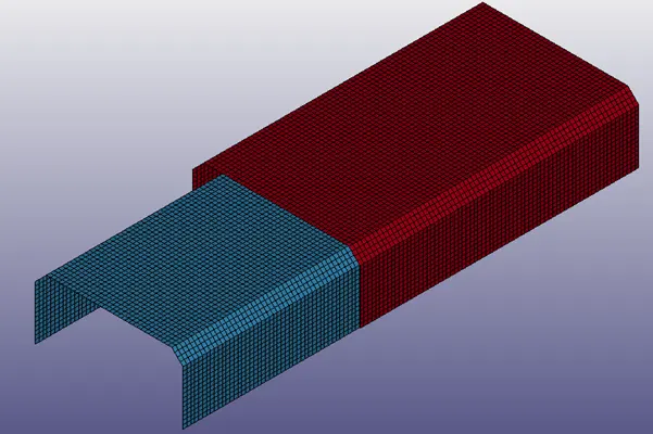
Input file
In the first case, spot weld are modelled as beam element. The nodes in each of the plates are identified.
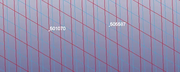
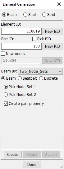
A beam element is then created using Element and Mesh heading, under Element Generation tab by defining two nodeset. The part ID can arbitrarily selected as 100.
Similarly, the rest of the beam elements are created and grouped under same part ID.
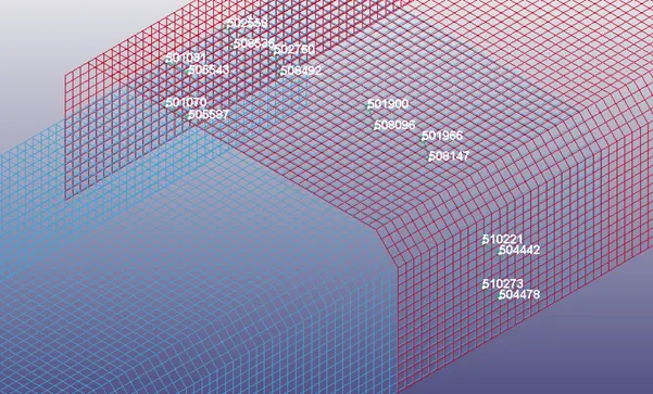
Care should be taken direct the vectors outward from inner plate to outer plate.
SOLID ELEMENT FORMULATION
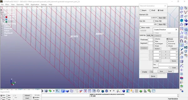
In case of creating solid element, the nodes identified previously are used. The solid elements are created by Solid face drag, by defining two nodes as shown above.
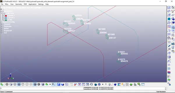
Similarly, the rest of the elements are created.
RIGIDWALL
Since, the input file doesn’t have a rigid wall, a planar rigidwall has to be created using *RIGIDWALL keyword or using entity creation. While creating the rigidwall by entity creation care has to be taken to denote the vector “N” as opposite to the travelling side as it is a semi-permeable membrane and allows penetration in the parallel side of vector and acts as rigid when in opposite direction.
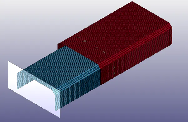
Rigidwall
(2) Section properties :
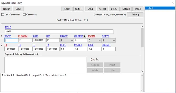
The section properties for the plates is selected as shell elements with element formulation ELFORM 2, and thickness is given as 1.2mm. The number of integration points is selected as 2.
The section properties of the spotweld is defined as beam.
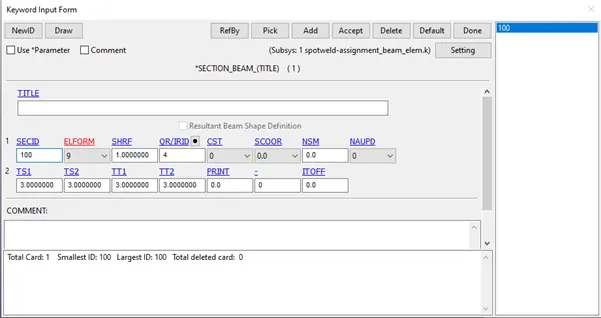
The other parameters required for defining the section are element formulation ELFORM 9 and Quadrature rule 4 as prescribed in the manuals. The area of the beam is in terms of width and breadth are defined as TS1, TS2 and TT1, TT2. The thickness is already defined as distance between the nodes.
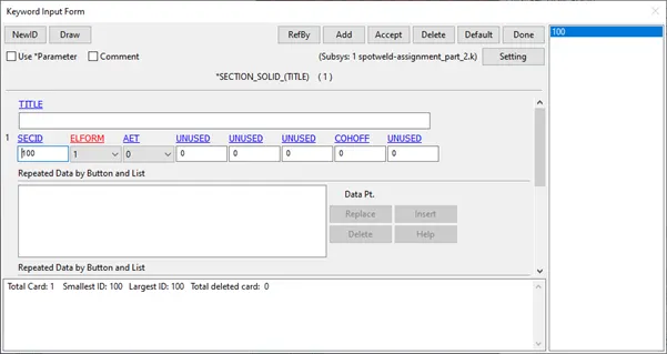
The section of the solid element spotweld is selected as solid with default element formulation.
(3) Material properties :
As the rigidwall is semi-permeable membrane and not an entity with nodes and elements, material properties cannot be defined. Since the plate assembly is assumed to be made of stainless steel, the material keyword is added with following properties. Non-linear properties keyword is added as it explains the non-linear behaviour after the crash.
MAT :
MAT_024 PIECEWISE_LINEAR_PLASTICITY
Density : 0.076 units
Young's modulus : 2e5 units
Poisson's ratio : 0.3
Yield stress : 370 units
Tangent modulus : 1.28e5 units
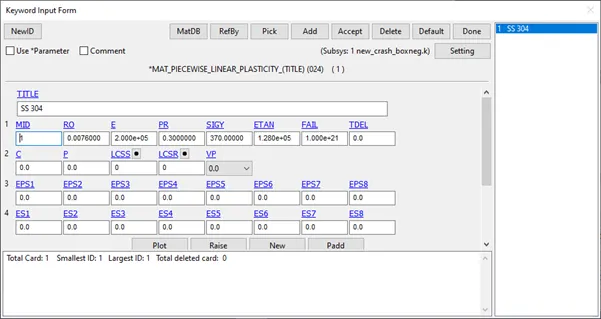
SS 304 Non-linear material properties
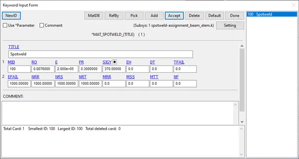
MAT_100
The spotweld material is assumed to be made up of SS 304 material. In this case force based failure criteria has been used to define the material properties. The effective plastic strain, axial force, maximum shear stress and resultant force have been purposely added at higher magnitude to prevent the collapse.
(3) Boundary conditions/Constraints/Loads:
Initial velocity: Since the crashbox is moving with a velocity of 50 kmph(13.89 mm/ms), the intial velocity is defined for all the nodes of the crashbox by creating node set ID.
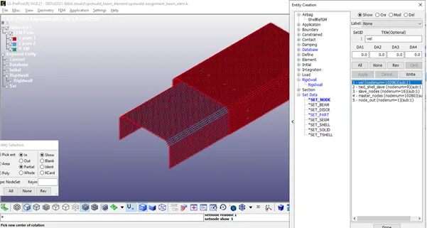
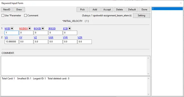
A value of 13.89 units is given in positive X direction.
(4) Contact :
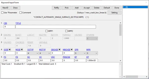
An automatic single surface contact is defined to study the impact of assembled plate against the rigidwall.
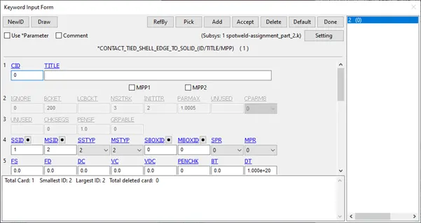
To study the effect of contact among the plates post crash, a tied shell edge to surface is defined between plates and the spotweld beam elements. The parts connected to the beam (plates) have been designated as master and beam elements have been designated as slave. The master and slave are defined by partset ID to make the selection hassle free.
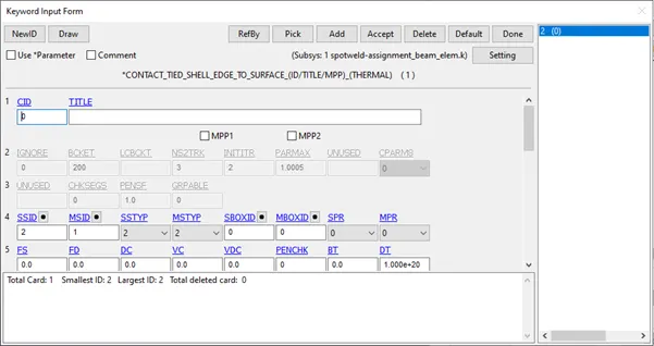
Similarly in case of solid spotweld elements, the plates have been designated as master and solid weld elements have been designated as slave. Tied shell edge to solid is used as contact formulation to study impact of contact forces upon crash.
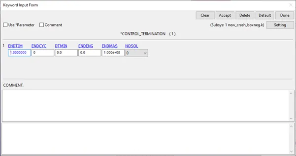
(5) Control :
Under control, the termination card is defined for specifying the end time/termination time. End time for this case is entered as 1 units.
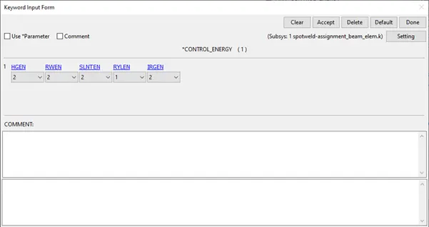
Hourglass energy and sliding energy are requested to be computed.
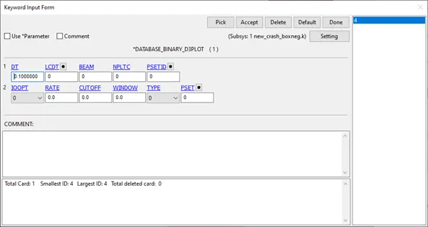
(6) Database :
Binary D3Plot is written for every 0.1 unit interval of time.
ASCII files and binary files of Global Statistics, Material energies, energies are requested to written for every 0.1 unit time to study the different energies during the impact.
(7) Part :
In this section, the different parts/components in the file are connected to their respective material ID and section ID.
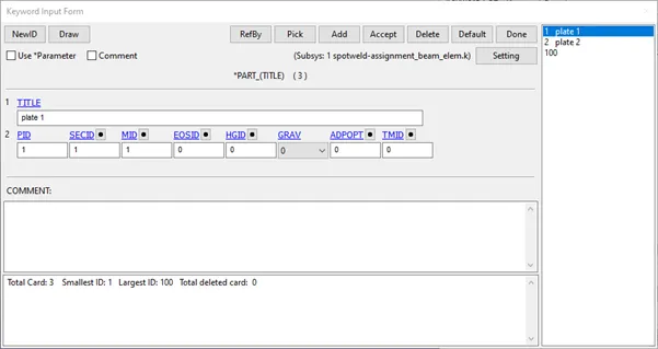
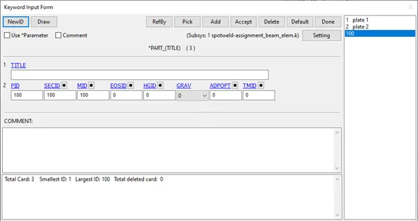
Once all the above is done, Model check is done to ensure all the parts are connected to their respective material, section and various components in contact/to be in contact are all well defined. A dialog box containing the cards - the errors, warnings, unreferenced, undefined are displayed. Approppriate action should be taken to overcome errors and warnings can be minimised.
SOLVING :
The above created input file is saved as keyword file (.k extension). This keyword file is solved using LS DYNA manager.
POST PROCESSING :
Various contour plots are plotted to check for sanity of the problem being solved. The animated file of the problem can be checked by running the d3plot file in the LS-PrePost.
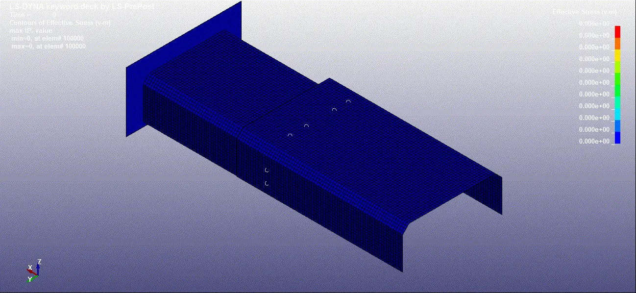
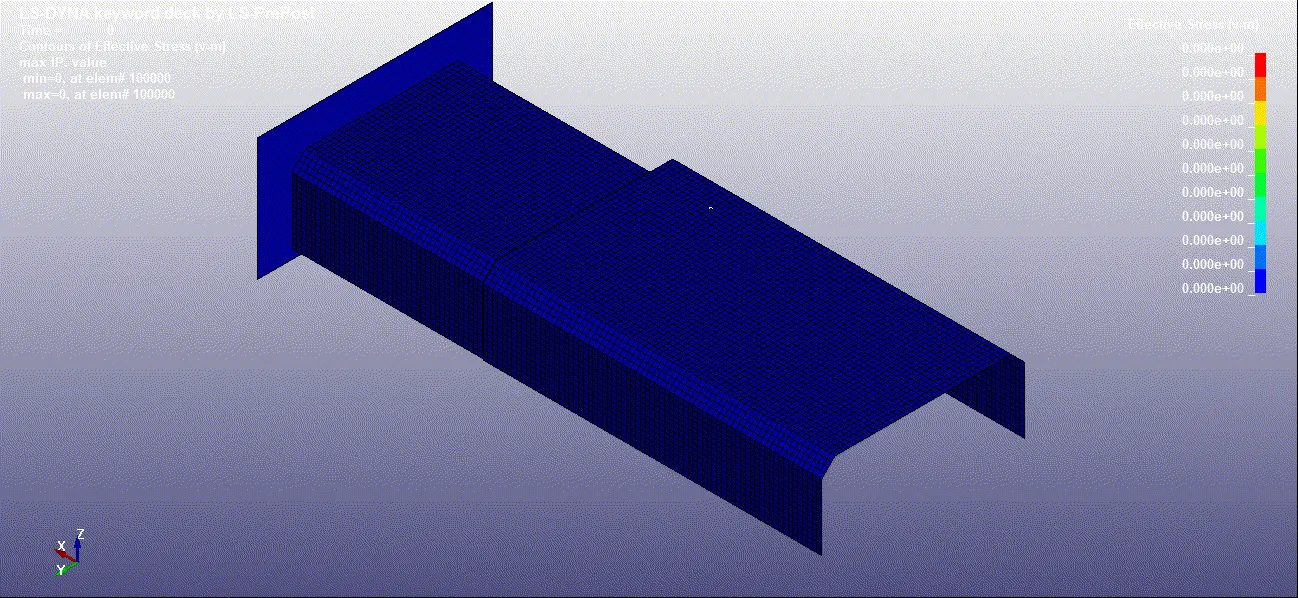
Beam Elform Solid Elform
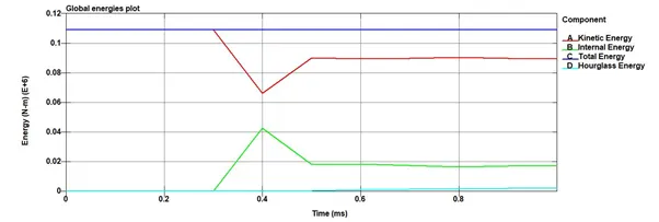
Verification: The performed analysis can be verified by drawing a plot energies.
Beam formulation
Solid formulation
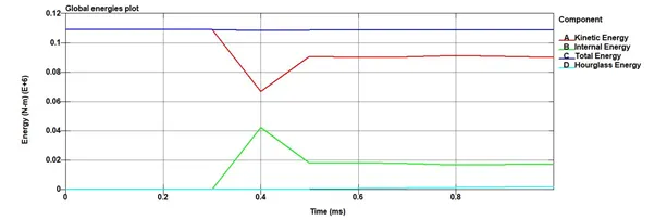
From the above plots, it is evident that the total energy is conserved. As there is no sliding between any parts, it is zero throughout. Hourglass energy increases on impact, but it accounts for 13% of internal energy, hence can safely be ignored.
With this background, we can proceed to extract other results.
Comparison of beam and solid element formulation
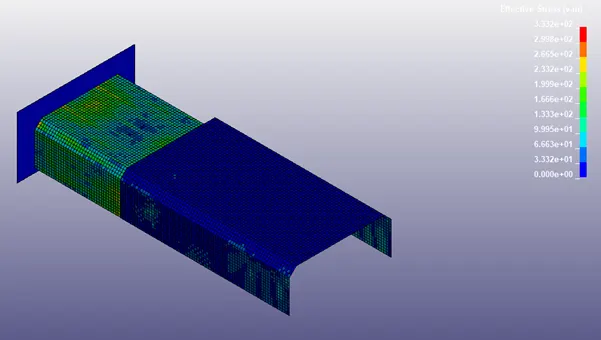
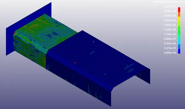
Beam Elform Solid Elform
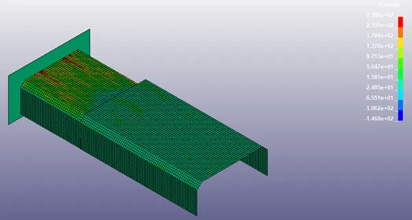
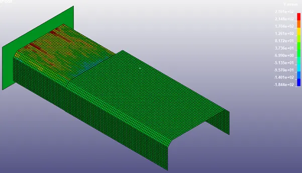
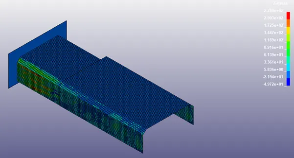
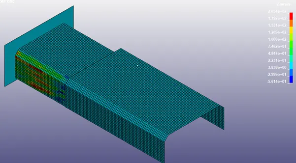
As evident from the graph, comparing the max Von-mises stress, the solid elform configuration reports a higher value of stress than that reported in case of beam which gives scope for further exploration of simulation.
Comparison of analysis for beam and solid element formulation :
Cross-sectional force :
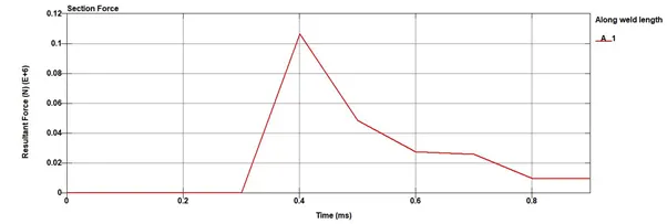
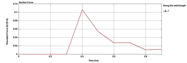
Beam Elform Solid Elform
Acceleration of node:
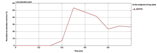
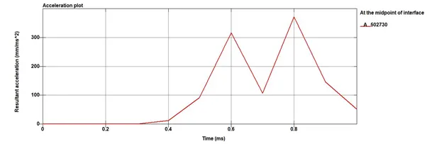
Beam Elform Solid Elform
Acceleration values varies because of different calculation for different element formulation. As beam is a no mass element and solid element has mass, there is a variation in acceleration because the kinetic energy is comparabe in both the cases.
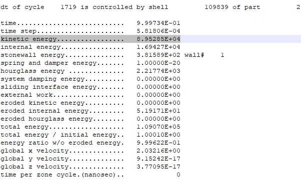
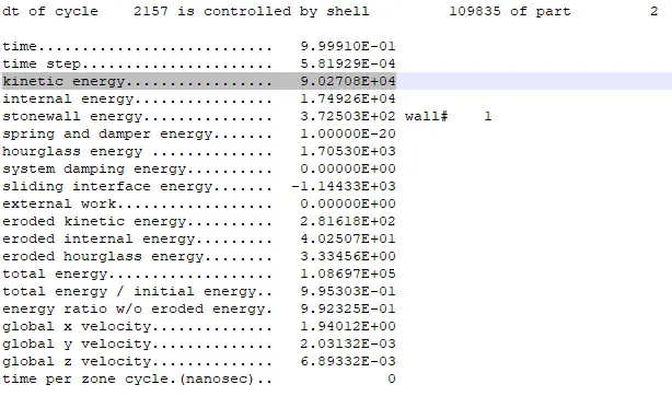
Beam Elform (at the endstep) Solid Elform (at the endstep)
Directional stress
X direction:
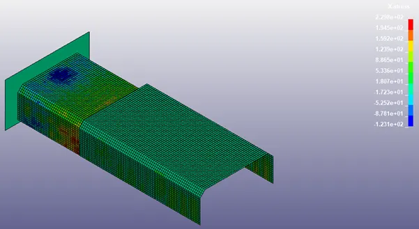
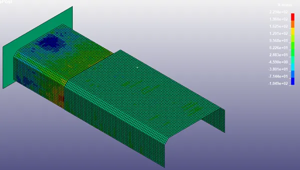
Beam Elform Solid Elform
Y stress
Beam Elform Solid ELform
Z direction
Beam Elform Solid ELform
Strain :
Lower Ipt:
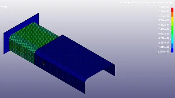
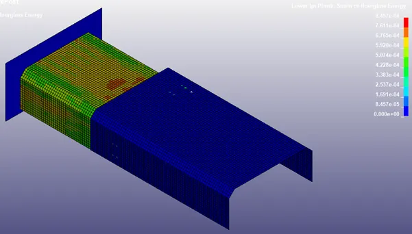
Beam Elform Solid Elform
Upper Ipt strain:
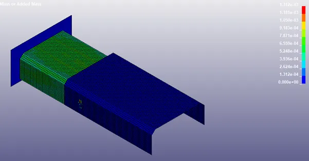
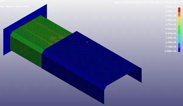
Beam Elform Solid Elform
The failure of the subsequent beam and solid elform elements are reported to be around 0.4 ms, given that endtime was 1 ms (approx. at 40% of simulation time)
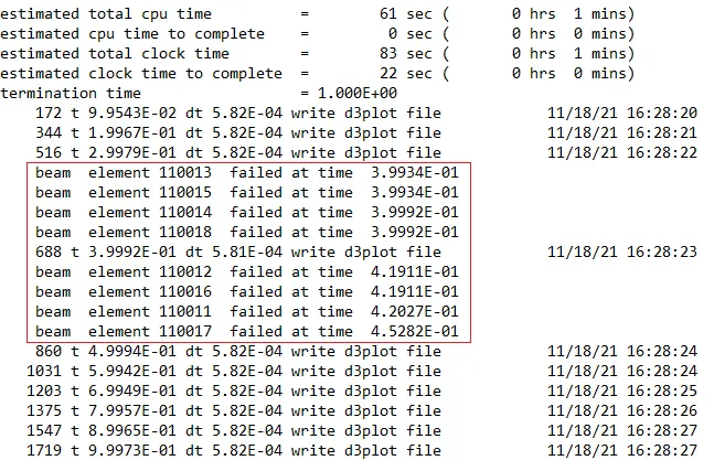
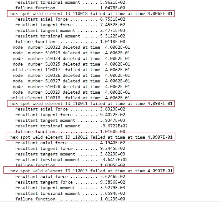
Beam Elform Solid ELform
Axial force & Shear force:
Beam Elform
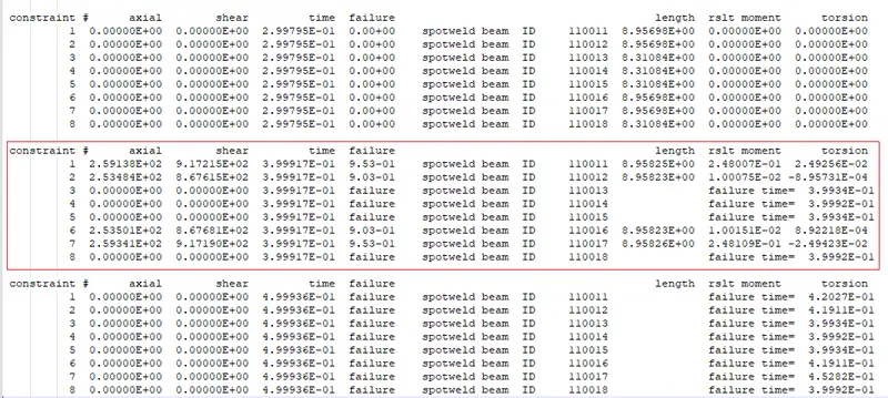
This is output of the swforce from ASCII output, the length column represents the thickness of the weld element (beam), the element 110013, 110014, 110015 which represents the elements at the middle of the cross section fails at 0.4 ms and leads to failure of subsequent elements which are on either side of the plate. The axial and shear force reported before failure are reported to be around 253-260 N which justifies failure criteria of 1000 N for EFAIL set in MAT_100 material card.
Solid Elform
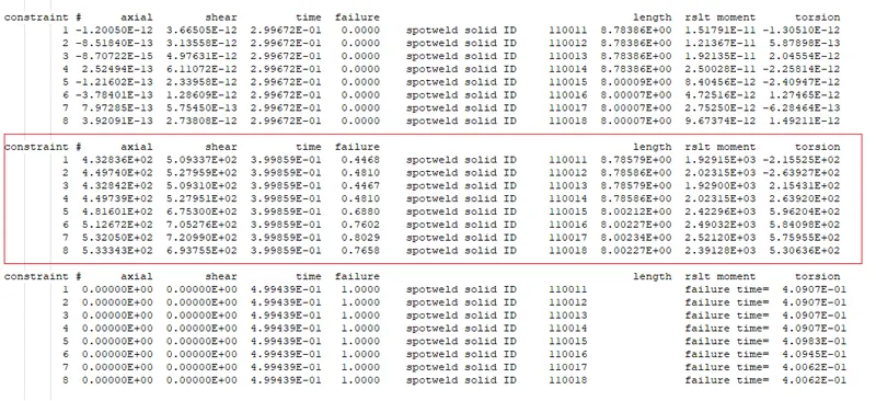
The maximum axial and shear forces reported for solid elform around 550-600 N which is less than threshold specified for the failure criteria in the material card.
Due to mass and stiffness in the the solid element, the forces reported are more than that in the beam elform.
Conclusion:
From the above results, it can concluded that running the simulation with beam and solid element formulation, reports comparable results of stress, however there are variation in values of strain owing to element configuration due to difference in stiffness. Since the simulation with beam elform takes less time to solve, this can be used as prelimnary case and can further be explored in detail with solid elform.
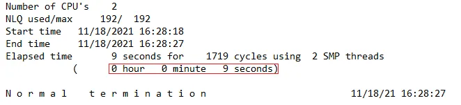
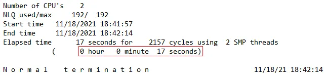
Beam Elform Solid ELform
Please follow for the input and output files : https://drive.google.com/drive/folders/1Zjswr7FaGoceg4kpxRMeISGfkTdV0FvJ?usp=sharing