Week - 4 - Crash Box Simulation
Aim : To simulate a crash test for a crash box.
Explanation:
Physics :
A crash box is a highly energy absorbing structure that crashes on application of loads and reduces impact on other components nearby. In the given problem, the crash box made of steel material with an initial velocity of 50 kmph crashes into a rigid wall.The simulation has to be done by varying thickness i) 1.2 mm and ii) 1.5 mm.
PRE-PROCESSING :
(1) Discretization :
The meshed file containing nodes and elements is provided. The file is imported into the LS-PrePost environment.The input file has rectangular channel configuration crash box.
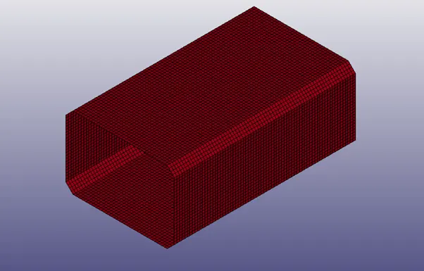
Input file
Since, the input file doesn’t have a rigid wall, a planar rigidwall has to be created using *RIGIDWALL keyword or using entity creation. While creating the rigidwall by entity creation care has to be taken to denote the vector “N” as opposite to the travelling side as it is a semi-permeable membrane and allows penetration in the parallel side of vector and acts as rigid when in opposite direction.
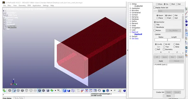
Rigidwall
(2) Section properties :
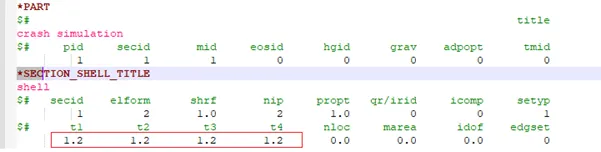
The section properties for the floor is selected as Shell elements with element formulation ELFORM 2, and thickness is given as 1.2mm. The number of integration points is selected as 2.

(3) Material properties :
As the rigidwall is semi-permeable membrane and not an entity with nodes and elements, material properties cannot be defined. Since the crashbox is assumed to be made of stainless steel, the material keyword is added with following properties.
Both the linear and non-linear properties are added in the simulation to check for rebounding or buckling if it comes in self contact.
MAT_001 ELASTIC
Density : 0.076 units
Young's modulus : 2e5 units
Poisson's ratio : 0.3
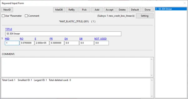
MAT_001 ELASTIC, SS 304 Linear material properties
MAT_024 PIECEWISE_LINEAR_PLASTICITY
Density : 0.076 units
Young's modulus : 2e5 units
Poisson's ratio : 0.3
Yield stress : 370 units
Tangent modulus : 1.28e5 units
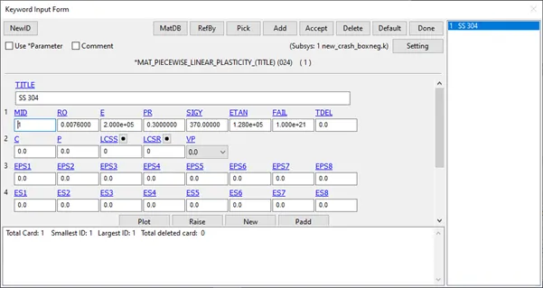
MAT_024 PIECEWISE_LINEAR_PLASTICITY, SS 304 Non-linear material properties
(3) Boundary conditions/Constraints/Loads:
Initial velocity: Since the crashbox is moving with a velocity of 50 kmph(13.89 mm/ms), the intial velocity is defined for all the nodes of the crashbox by creating node set ID.
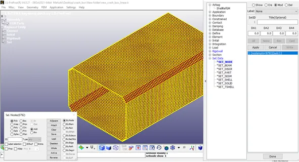
Creation of node set id (NSID)
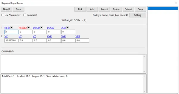
A value of 13.89 units is given in positive X direction.
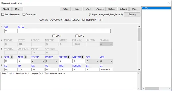
(4) Contact :
An automatic single surface contact is defined to study the impact of crash box against the rigidwall.
(5) Control :
Under control, the termination card is defined for specifying the end time/termination time. End time for this case is entered as 1 units.
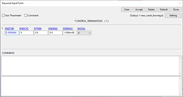
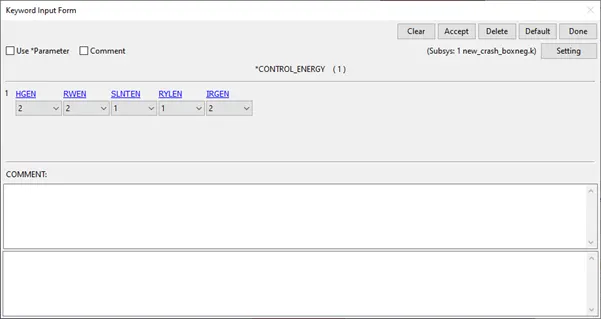
For the verification of the simulation hourglass energy, sliding energy has to be computed, hence Control_energy card needs to be added to compute the required energies.
(6) Database :
Binary D3Plot is written for every 0.1 unit interval of time.
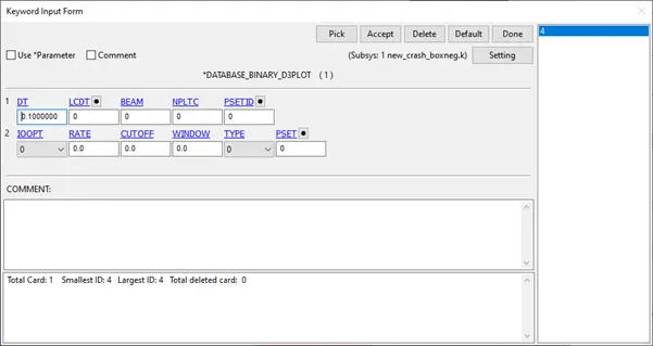
ASCII files and binary files of Global Statistics, Material energies, energies are requested to written for every 0.1 unit time to study the different energies during the impact.
(7) Part :
In this section, the different parts/components in the file are connected to their respective material ID and section ID.
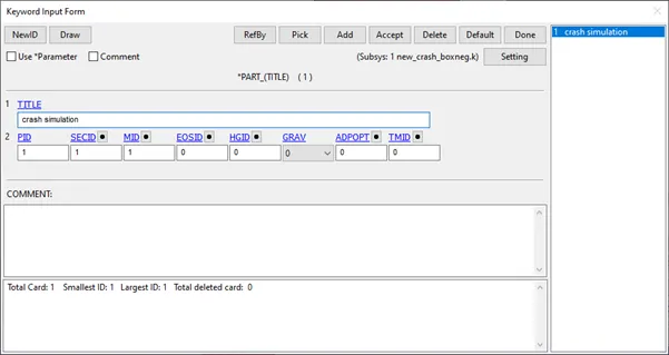
Once all the above is done, Model check is done to ensure all the parts are connected to their respective material, section and various components in contact/to be in contact are all well defined. A dialog box containing the cards - the errors, warnings, unreferenced, undefined are displayed. Approppriate action should be taken to overcome errors and warnings can be minimised.
SOLVING :
The above created input file is saved as keyword file (.k extension). This keyword file is solved using LS DYNA manager.
POST PROCESSING :
Various contour plots are plotted to check for sanity of the problem being solved. The animated file of the problem can be checked by running the d3plot file in the LS-PrePost.
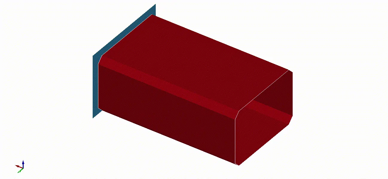
Animation of the plot
Verification: The performed analysis can be verified by drawing a plot energies.
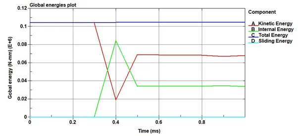
From the above plot, it is evident that the total energy is conserved. As there is no sliding between any parts, it is zero throughout. With this background, we can proceed to extract other results.
Comparison of linear and non-linear material properties
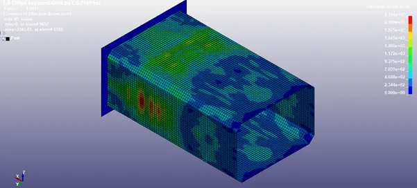
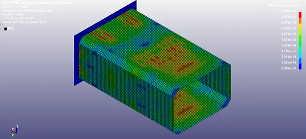
Von-mises stress for linear material property Von-mises stress for non-linear material property
As the effective stress reported in the simulation with non-linear property is more than the one without non-linear property, it can inferred that linear material property is not suffice to explain the behaviour and gives scope for an elaborated study. Hence, the comparison of varying the shell thickness is conducted using the non-linear material properties.
The simulation can be for 1.5 mm shell thickness by editing the .k file.
Comparison of analysis for 1.2 and 1.5 mm thickness respectively
Cross-sectional force across plane at the middle of crash box:
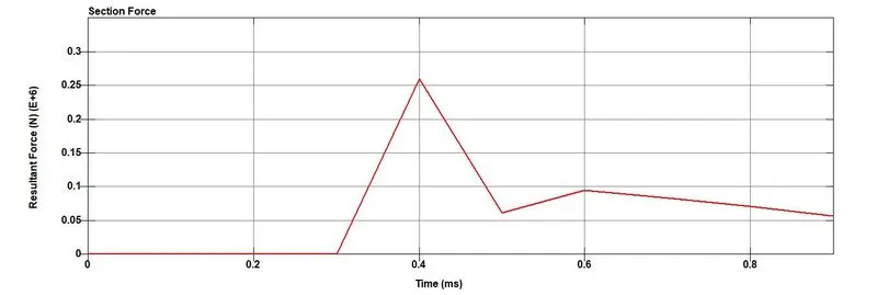
1.2 mm shell thickness
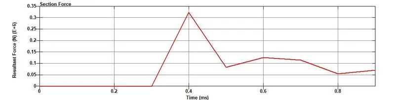
1.5 mm shell thickness
The maximum cross sectional force is seen at the time of impact, and gradually transfers its kinetic energy to the rigid wall. The force increases with increase in the thickness of the shell, because of increased mass.
Acceleration plot of node at the middle of the crash box:
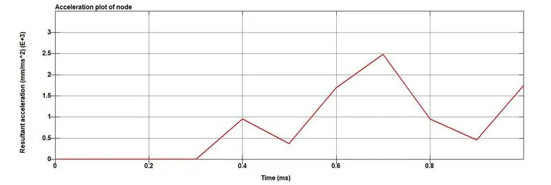
1.2 mm shell thickness
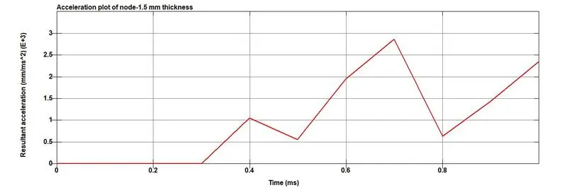
1.5 mm shell thickness
The maximum acceleration of the node at the middle of cross section differs for 1.2 and 1.5 mm thickness because of the increased mass and hence higher kinetic energy.
Directional stress:
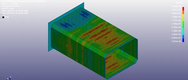
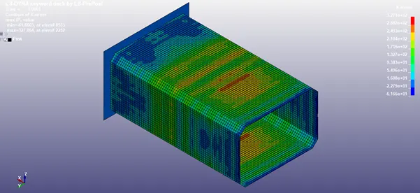
X direction- 1.2 mm thickness X direction- 1.5 mm thickness
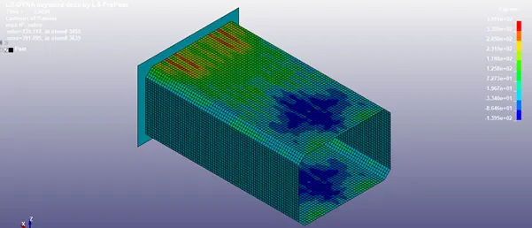
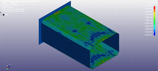
Y direction- 1.2 mm thickness Y direction- 1.5 mm thickness
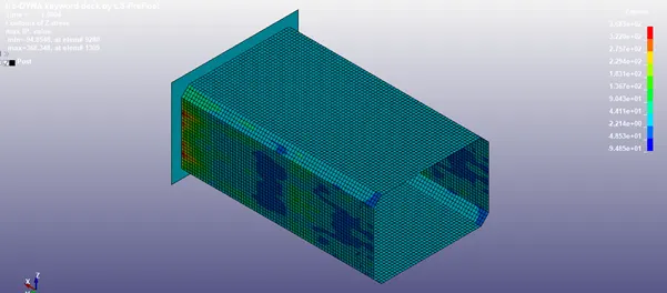
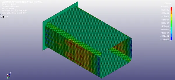
Z direction- 1.2 mm thickness Z direction- 1.5 mm thickness
From the stress graphs, it can inferred that maximum stress values marginally increases with increase in the thickness of the shell i.e the stress carrying capacity of the crash box increases with increase in thickness.
Strain:
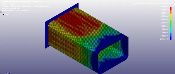
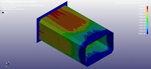
Lower Ipt strain- 1.2 mm thickness Lower Ipt strain- 1.5 mm thickness
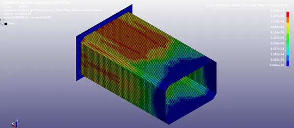
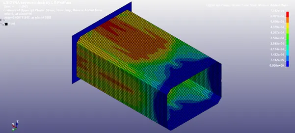
Upper Ipt strain- 1.2 mm thickness Upper Ipt strain- 1.5 mm thickness
Accordingly, the effective strain increases with increase in thickness of the shell, due to increase in mass and hence higher stress carrying capacity.
Hence, it can be inferred that 1.5 mm shell thickness has enhanced stress carrying capacity compared to 1.2 mm thickness shell at the cost increased mass.
Please follow the link for the input and output files : https://drive.google.com/drive/folders/1Z2CDzbPV6gcU6yl89QxWRokgGTaebscJ?usp=sharing