Bird Strike - Project - 2
WEEK 12:
OBJECTIVE:
To perform a bird strike simulation in LS-DYNA and evaluate the results.
PROCEDURE:
The project file contains hub, blade, engine casing, and bird geometry. The blade rotates at a constant velocity and the engine casing should remain stationary. The cylindrical bird travels along its own axis toward the engine and hits the blades. All the parts should be in a single input file and should have consistent numbering.
The given file contains four different parts, hub, blades, engine casing, and the bird. So, these parts are separated and placed into a single input file. This can be done by creating new subsystems and moving parts to respective subsystems or it can be done easily by keeping one part and deleting other parts from LS-PrePost. Similarly, all parts, contacts, controls, materials, sections, and velocities are separately designed by respective .k files and are called into the main file through *INCLUDE keyword. Important properties would be discussed below and the *INPUT keyword will be discussed at the end. The unit system chosen for this analysis is gm-mm-ms.
The Young’s modulus for the bird is given as 2000MPa and the casing is given as 200GPa. Both bird and casing are modeled by an elastic material. Figure 1.1 depicts the elastic material properties defined for the bird. The density and Poisson’s ratio values are taken similarly to human muscle values. Similarly, the engine casing is defined with properties that are similar to the metal. Figure 1.2 depicts the material card definition for engine casing.
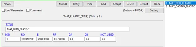
Fig 1.1: Elastic material used to model the bird
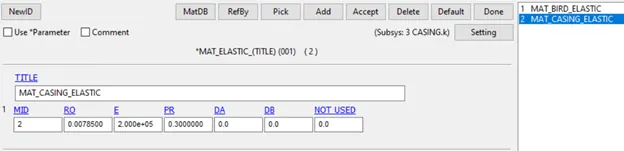
Fig 1.2: Elastic material used to model the engine casing
The engine blades are modelled with the piecewise linear plasticity model. These blades are the outermost parts of the engine are called as fan blades. These blades work at low temperatures and are lightweight. They are made up of titanium and so titanium material properties are used to define these blades. The material properties defined are shown in figure 1.3 and as well below [1].
Massdensity(RO)=0.0045gm(mm)3Massdensity(RO)=0.0045gm(mm)3
Young′sModu––s(E)=1.6⋅(10)5gm(mmms)2Young′sModu̲s(E)=1.6⋅(10)5gm(mmms)2
Poisson′sratio(PR)=0.34Poisson′sratio(PR)=0.34
Yieldstress(SIGY)=220gmmmms2Yieldstress(SIGY)=220gmmmms2
tan≥ntModu––s(ETAN)=1160gmmmms2tan≥ntModu̲s(ETAN)=1160gmmmms2
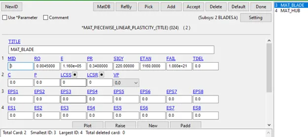
Fig 1.3: Elasto-plastic material properties used to model the blades
The hub is also modelled with piecewise linear plasticity model and the material properties for hub defined similarly to the general metal. Figure 1.4 depicts the material card assignment for the hub.
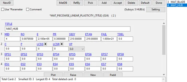
Fig 1.4: Elasto-plastic material properties used to model the hub
The blades, casing and bird are made up of shell elements are defined with shell section properties with 1mm thickness. Whereas, the hub is made up of solid elements and defined with solid section properties.
The shell thickness of 1mm is considered for bird and blade geometry. The shell thickness of 2mm is assigned for casing geometry. All other section properties are set to default values. The contact defined is AUTOMATIC_SINGLE_SURFACE, here all the part are included for single surface contact. This is done by assigning the SSID=0. Fig 1.5 depicts the contact card used to define contacts between all the parts.
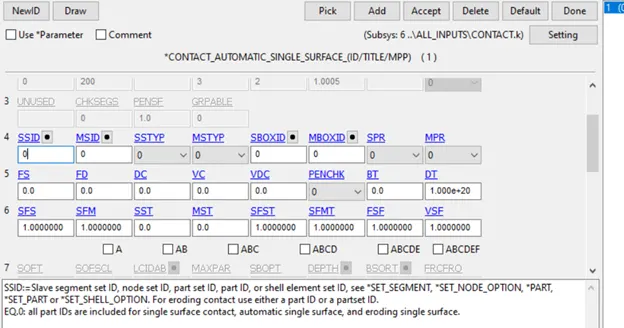
Fig 1.5: Contact definition for all parts
The velocity for the blades and the bird has given by *INITIAL_VELOCITY_GENERATION keyword. Figure 1.6 and 1.7 depicts the rotational and translational velocity assigned to blades and bird respectively. Termination time is defined by a control termination keyword.
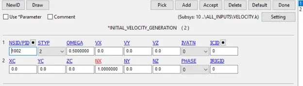
Fig 1.6: Velocity assigned for blades
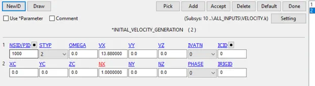
Fig 1.7: Velocity assigned for bird
All the parts bird, hub, casing and blades are made as different input files. All velocity and contact boundary conditions are assigned by separate input files. The material and control cards are also assigned with separate input files. Figure 1.8 depicts all the different input files which are called in the main input file for solving the problem.
The specific node, element, section, part, material numbering approach is followed in this analysis. All nodes are numbered above 100000, elements are numbered above 500000, parts are numbered above 1000 and material and sections are numbered above 10000. This numbering is done by renumbering the option in the model and part utility.
This renumbering is done in the last main file (MAIN.K). Figure1.9 depicts the renumbering option used in LS-PrePost. Figure 1.10 depicts the final geometry used for the simulation.
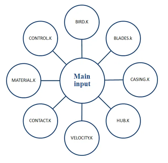
Fig 1.8: Files included in the main input file
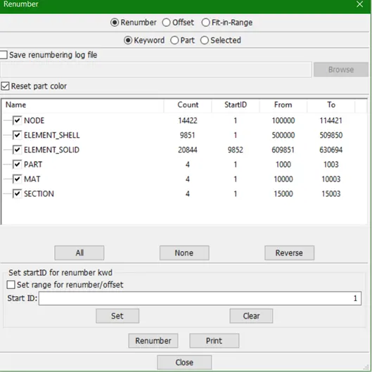
Fig 1.9: Renumbering of all entities
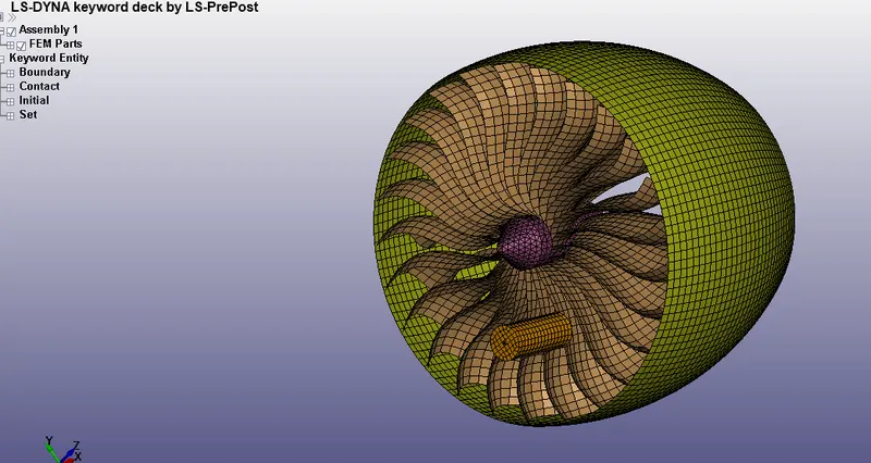
Fig 1.10: Final geometry used for bird strike simulation
RESULTS AND DISCUSSION:
Various output parameters are evaluated and are discussed in the following section.
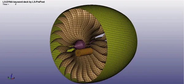
ANIMATED RESULTS OF BIRD STRIKING ON THE ENGINE BLADES
Stress values:
Figure 1.11 depicts effective stress contour globally. Higher stress values can be seen on the blade which impacts the upcoming bird. The stress value passes the yield stress of the blade and hence there would be yielding in the blade material. Figure 1.12 shows the stress vs time behaviour of the element on the impacted blade. The stress values peaks for a short duration during the impact but fluctuates afterwards due to the shock waves.
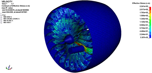
Fig 1.11: Effective stress contour
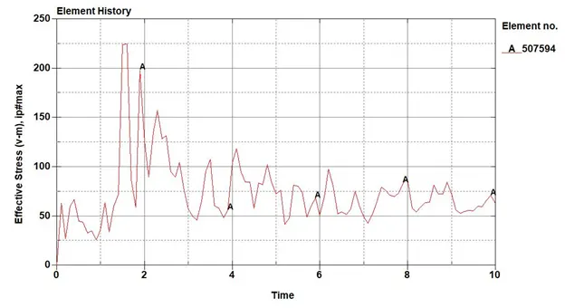
Fig 1.12: Effective stress value for an impact element of a blade
Strain values:
Figure 1.13 depicts the effective plastic strain contour for the whole geometry. As the stress values after the impact are higher than the yield stress, there is a permanent deformation in the blades. The plastic deformation on the impacted blade can be seen in the figure below. The maximum plastic strain is 0.008 mm/mm. Figure 1.14 shows the effective plastic strain vs time behaviour of the impact element. The strain suddenly increases during the impact and remain constant until the end. The plastic deformations are non-recoverable so they remain in the blade.
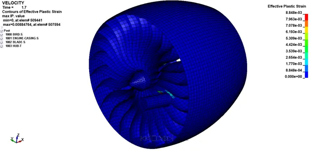
Fig 1.13: Effective plastic strain contour
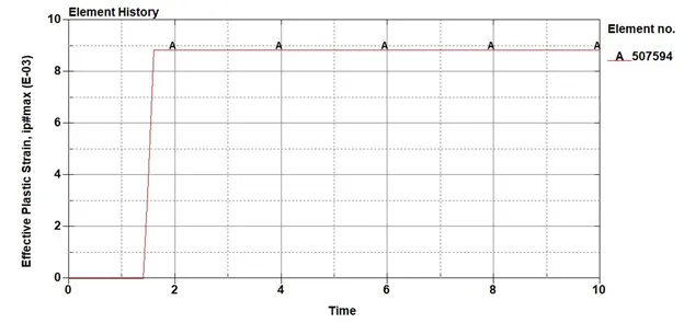
Fig 1.14: Effective plastic strain value for an impact element of a blade
Energy values:
Figure 1.15 shows the global energy of the system. There is no significant change in the energies due to the impact. The system possesses large energy due to the rotation of blades and the impact is not that severe to change the existing energy significantly.
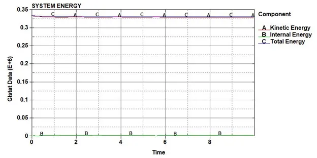
Fig 1.15: Global energy
But from figure 1.16 it can be seen the energy values changes for the bird drastically. This is because the bird possesses kinetic energy because of the linear velocity at the start. This energy drops down by a certain amount due to the impact and the bird changes its path with some extra velocity imparted by the rotating blades. This increases the kinetic energy further after the impact and the internal energy is also increased by some amount due to the collision. But the energy levels are less and not that significant compared to global energy.
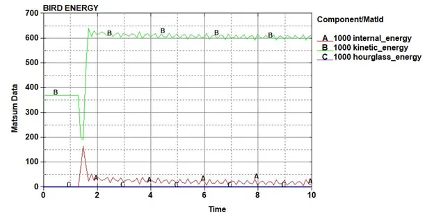
Fig 1.16: Bird energy
Figure 1.17 depicts the energy for the engine casing. It can be seen, kinetic and internal energy increases due to the shock wave and vibrations after the impact in the casing. These energies decay after some time as the vibrations are reduced. The casing energy is even smaller than bird ad are not that significant as compared to global energy.
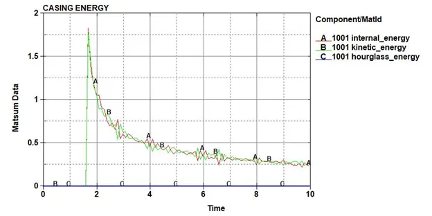
Fig 1.17: Casing energy
CONCLUSION:
The bird impact analysis is performed in LS-DYNA. From post-processing, the severity of the bird impact on the blades is analyzed. There is some permanent deformation in the blade which is impacted by the bird. There is no significant change in global energy.