Backdoor Wiring Harness Design Using CATIA V5
Wiring Harness on Back Door Assemby
Aim:
- To route the wiring harness on given car body and prepare flatten view drawing in CATIA V5.
- Then applicable for all packaging rules, industry best practices studies and also apply protection coverings as required
Objectives:
The goal of this project is to route the wire harness and create a plan view of the back door of the car. All sorts of packaging rules need to be considered when wiring a wire harness, and industry-based practices must be demonstrated in the design of the wire harness. Harness design should provide all necessary details such as clearance, clip/clamp selection, harness mounting requirements, harness continuity.
Wiring Harness Back Door:
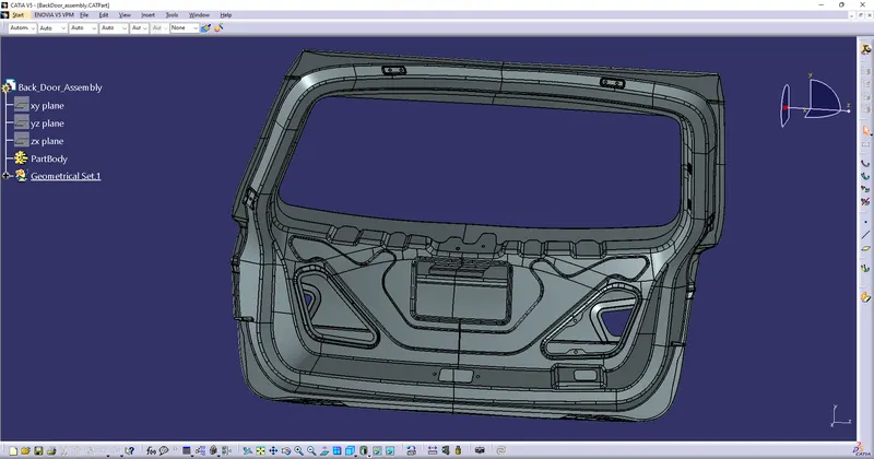
In the case of car doors, the wires bend as the door is opened and closed. When using a car every day, the door is opened and closed many times. In the case of a back door, the trunk may be opened and closed many times in daily life. The rear door wiring harness is primarily used to connect brake lights, license plate lights, rear wiper motors and defogger connections. Wire harness routing must be properly maintained using all supporting components such as clips, clamps with suitable protective coverings, grommets, etc.
Rules Followed while Routing:
- Provide clips/clamps as per requirement.
- Be careful not to make any mistakes in the design of the wire harness. Additional clips/clamps can be used to prevent damage to the housing.
- Please allow slack if necessary. 5-15% slack is sufficient.
- Avoid routing along sharp edges or protect your wiring harness.
- Keep a safe distance and keep wire harnesses away from heat generating components.
- Depending on the ambient temperature, protection should be provided as required.
- The length of the branches should be 50mm or more.
- The minimum distance between two branch points should be at least 50 mm.
- The minimum distance between clip and branch point should be at least 25 mm.
- Avoid putting too many sheet metal brackets on the engine
- Wiring harnesses should be easy to assemble and easily accessible.
- If you use dummy connectors, make sure the positions you define are practical. Bundle diameters and other arrangements can be defined appropriately for wire harness routing.
- If your packing area is too small and your packing restrictions are high, you can consider creating wire harness ducts that can be used to effectively guide and protect your wire harnesses.
Creating Wiring Harness For Back Door Assembly:
Step 1: Creating Context Assembly:
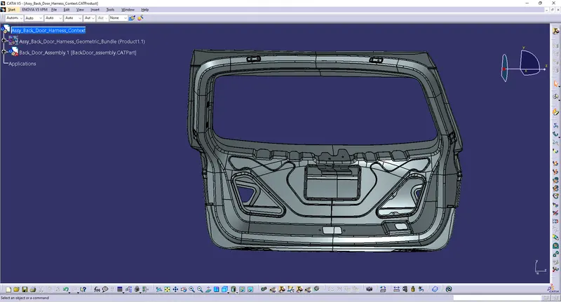
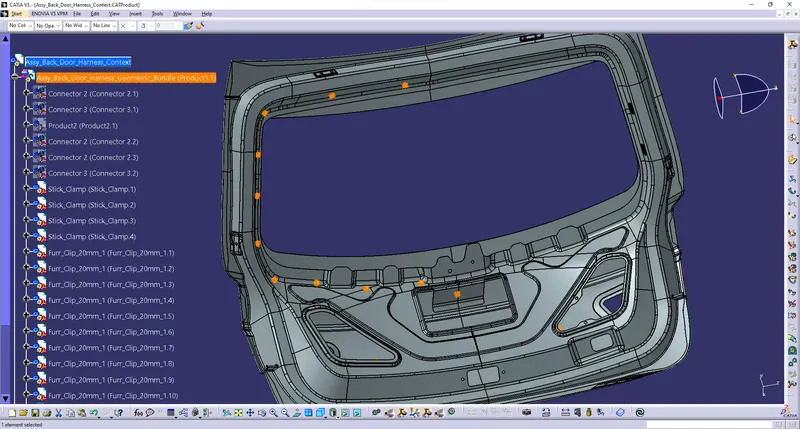
- As shown in the image above, the backdoor wire harness context assembly was created to serve as the main assembly.
- The context assembly contains the backdoor assembly data and the backdoor wire harness geometry bundle assembly.
Step 2: Define the Connector for our requirement:
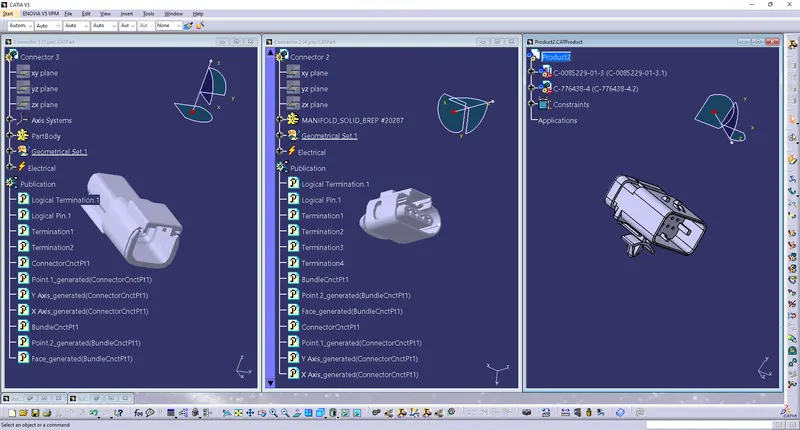
- Here we are using three type of conector and tose were mention below
- C-776438-4 which has 12 pole connector used has interconnection connector
- c-1563689-1-b-3d, which has 4 pole connector used has tail gate and wiper motor
- C-282080-1, Which has 2 pole connector for the number plate light
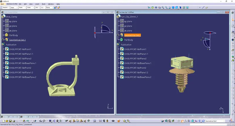
- A furr trip clip used to attached to the back door to provide support and act as a guide channel. Therefore, we must first define them electrically using geometric parameters, the entry and exit points on both the left and right sides of the clip. As shown in the figure below.
- Then Stick clamp also attached to the back door for the tail gate light. therefore, we must first define them electrically using geometric parameters, then given entry and exit point on both side for the clamp as shown in the figure below
Step 3: Mounting the furr trip clips & Stick clamp:
- Mounting furr trip clips and also sticky clamp as per our requirement and mention below
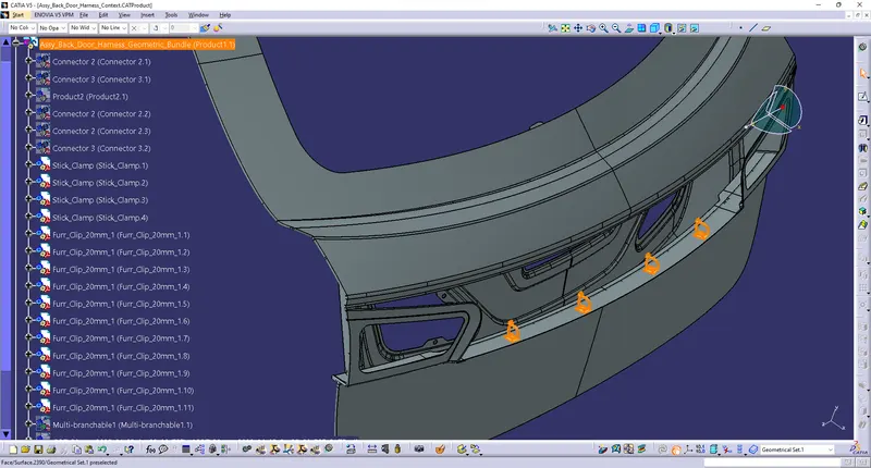
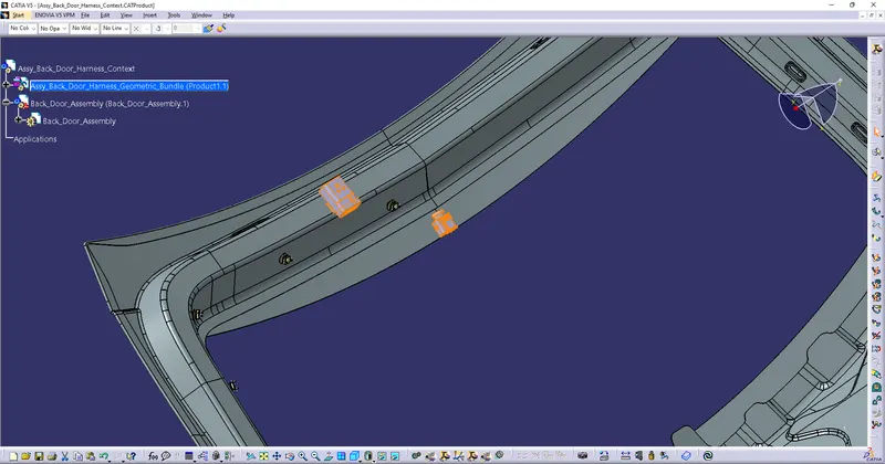
- Then Place all connector as per place in the back door
Step 4: Bundle routing on all connector:
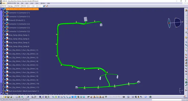
- Bundle segments are routed from connector plugs to Furr Trip clips and routed to 4-pin and 2-pin connectors. while maintaining a bend radius has 1.4
- I used 5-15mm thickness of the bundles
Step 5: Adding Protective covering on Bundle segement:
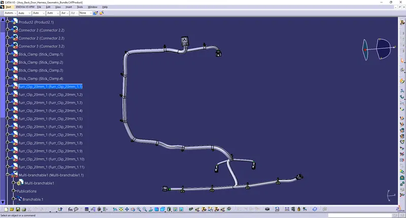
- Here is the below image I made with the entire rear door wire harness routing. Next, all bundle segments must be fitted with protective covers.
Step 6: Checking Bundle Connectivity:
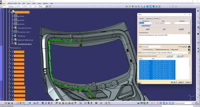
- In this step, first make sure the multibranch feature is selected, then Edit -> Search -> Advanced -> Workbench - Electrical -> Type-Bundle-Segment -> Attributes - Select "Fully Connected" to continue.
- Select True to display all connected bundle segments, or False to display all unconnected bundle segments.
- In this case, I selected the True option and checked the results. All bundle segments are highlighted to indicate that they are all electrically connected as shown in the image below.
Step 7: Creating flatten view Back Door Assembly Wiring Harness:
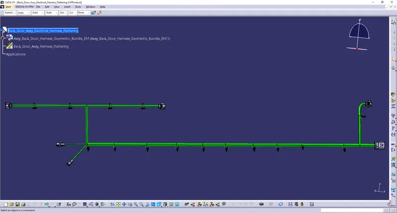
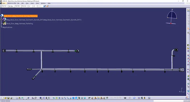
- In this step, we will use the Catia V5 Electrical Harness Flattening workbench to create a flattened view. Also, you must ensure that the flat file is saved in the same folder as the other harness assembly files.
- The bundle assembly was extracted into a product file for flattening the Back door harness and flattened along the face of the connector.
- Then Develope a flattern view of the product
- The flattening workbench's rotation function must be used to rotate the bundle segment that connects to the four camshaft connectors.
- Note that the "face" of the connector plug acts as a flattening plane, so the bundle segment can only rotate along this plane.
- We fine-tuned the harness using various functions such as bending, rotating, and rotating to improve its presentation.
Step 8: Creating flattern view drawing for the Back Door Assy Wiring Harness:
- In the image above, we have created a new drawing file and defined all the necessary drawing parameters. A front view of the backdoor harness flattened product file must be included in the drawing file. We need to define the drawing properties as shown in the previous figure. Note that 3D Wireframe is always enabled in the "tightening settings". If this option is not activated, bundle segments are not displayed in drawing views. The final drawing view of the backdoor harness flattens the view.
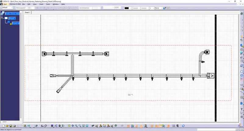
- Overall Output Images:
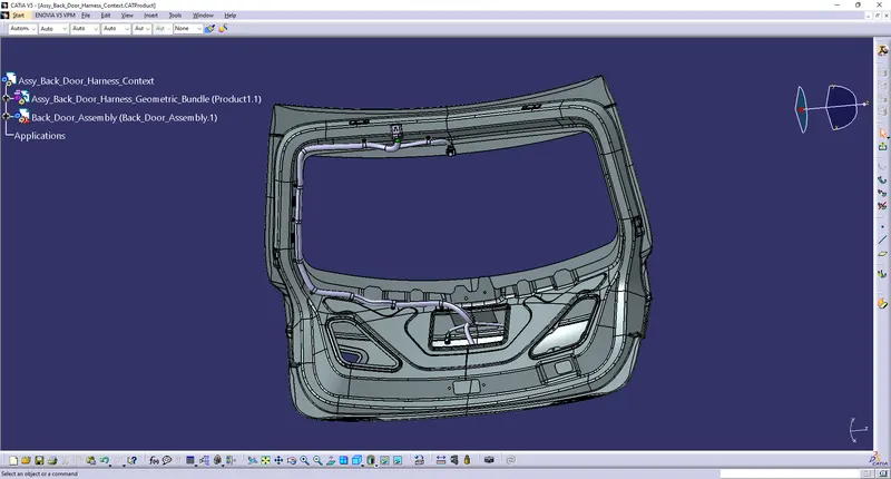
Conclusion:
Considering all packaging regulations and industry standards, you have successfully completed the assembly of the vehicle rear door wiring harness. Harness flattening and flattened view drawing preparation were also performed using CATIA v5 software.
Files:
- Assembly file were uploaded in "Project 2.zip" file and the file were uploaded below
- Then output image and other files like connector, flattern, drawing sheet files also uploaded in the same zip file