AutoCAD_Reinforcement Bar Shapes, Types of Doors, Creating symbols legend and Creating standard template_Week 8
Q1)
AIM :
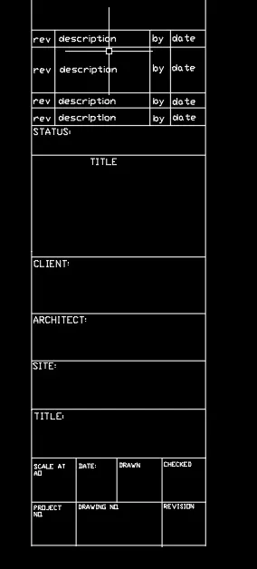
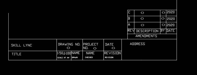
Create the templates as shown in Figures. Take the size of the title block as per industry standards or
you can assume it as per the size of the paper. Use text and attributes wherever required. After creating
the title block you need to save it as a block with names: Custom1_titleblock and Custom2_titleblock,
respectively.
PROCEDURE:
open the autocad and invoke the line command by pressing l enter.
draw the schedule as shown in figure.
write the texts inside the boxes as shown in figure.
after completing the figure, press B enter ,a dialogue box will appear.
select the option pick point and pick the point on the figure.
then click option select object and select the object and name it.
block will be saved and we can use it by using i enter command.
it will ask to select the base point ,press enter or it can be dragged on to the screen.
same procedure is to be followed for the second picture.
Q2):
AIM :
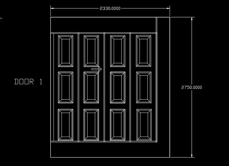
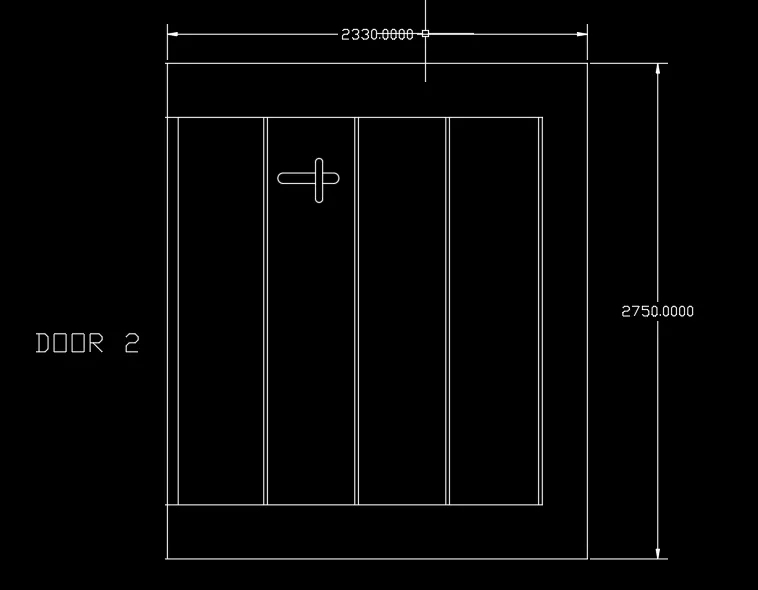
Create the doors type for warehouse as shown in the Figure. You need to create each door type as per
standard size or given dimensions. Create the blocks of this door type after creating them.
PROCEDURE :
open the autocad and press un enter and set the units to feet and engineering, invoke the rectangle command.
enter the values 2330,2750, a rectnagle will be created and take the outside offset of
assumed distance but close to it.
divide this door into four parts by taking offsets of 550 units vertically and take the offsets close to it.
to draw the inside panels just draw a rectangle and take an offset close to it and then take another offset close to centre.
join the lines from all four sides ,copy this and place it throughout the figure wherever drawn.
for the second door just extend the lines drawn in this as divider lines.
and erase the inner panels and mark the dimensions.
after completing the figure, press B enter ,a dialogue box will appear.
select the option pick point and pick the point on the figure.
then click option select object and select the object and name it.
block will be saved and we can use it by using i enter command.
it will ask to select the base point ,press enter or it can be dragged on to the screen.
Q3):
AIM :
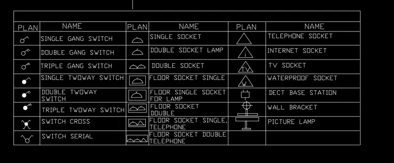
Create each symbol as a block with the name given in the legend. After creating the blocks arrange
them in the legend as shown in the Figure.
PROCEDURE :
open the autocad draw a rectangular box as shown in figure .
press un enter and set the units to feet and engineering.
draw the rows and columns as shown in figure and mark the texts as shown in figure.
after completing the figure, press B enter ,a dialogue box will appear.
select the option pick point and pick the point on the figure.
then click option select object and select the object and name it.
block will be saved and we can use it by using i enter command.
it will ask to select the base point ,press enter or it can be dragged on to the screen.
Q4)
AIM :
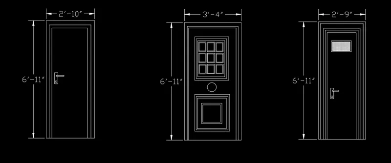
Create the door type for residential building as a block. Save the name of the blocks as type. Use given
dimensions or assume dimensions as per industry standards.
PROCEDURE :
open the autocad and press un enter and set the units to feet and engineering.
with the help of rectangle command draw a rectangle of 6'11*2'10.
take the offsets of assumed dimensions close to the top three sides.
latch of the door can be drawn with the help of rectangle and circle command.
coming to the second door , draw a rectangle of 6'11*3'4 using rectangel command.
draw another set of rectangles close to each other on the top side.
draw a set of 9 squraes in it covering the middle portion in it.
draw a circle below it and draw another set of rectangles close to each other at the bottom.
coming to third door draw a rectangle of 6'11*2'9.
take the inner offsets close to each other as shown in figure.
and draw a small rectangle with rectangle close to it ,latch can be drawn using rectangle command at the mid of door.
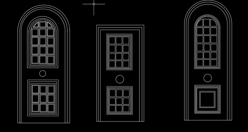
other three doors also can be drawn with the help of rectangle and offset command as shown in figure.
after completing the figure, press B enter ,a dialogue box will appear.
select the option pick point and pick the point on the figure.
then click option select object and select the object and name it.
block will be saved and we can use it by using i enter command.
it will ask to select the base point ,press enter or it can be dragged on to the screen.
Q5):
AIM :
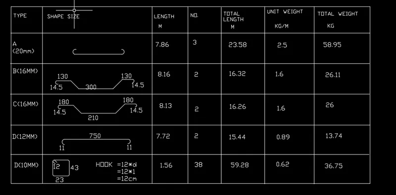
Create each shape as a block as shown in the Figure. Save the block and insert them on the table as
shown in the Figure.
PROCEDURE :
open the autocad and set the units to feet and engineering by pressing un command.
draw a rectangle as shown in figure using rec command.
make the rows and columns as shown in figure.
write the texts in the drawn rows and columns as shown in figure.
draw the figures as shown in shape size column using line command.
after completing the figure, press B enter ,a dialogue box will appear.
select the option pick point and pick the point on the figure.
then click option select object and select the object and name it.
block will be saved and we can use it by using i enter command.
it will ask to select the base point ,press enter or it can be dragged on to the screen.
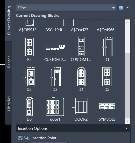
interface that appears after saving all the blocks can be invoked by insert command ( i enter)
from here can be dragged on screen and can be placed.