Construction Technology_Vaastu Shastra & Calculation of loads_Project 2
AIM:
To sketch a G+1 floor residential plan, according to vastu shastra and list down the names of the structural drawings required to be provided to the site for construction.also assume the sizes of structural elements (columns ,beams, slab) and accordingly calculate the individual corresponding loads from the members as per IS code.
INTRODUCTION:
vaastu shastra is the traditional indian system of architecture originating in india. texts from the indian subcontinent desribe principles of design,layout, measurements ,ground preparation space arrangement and spatial geometry. vastu shastra incorporate traditional hindu and buddhist believes. the designs aim to integrate architecture with nature, the relative functions of various parts of the structure and ancient beliefs utilising geometric patterns ,symmetry and directional alignments. vastu shastra are the textual part of vastu vidya - the broader knowledge about architecture and design theories from ancient india. vastu vidya knowledge is a collection of ideas and concepts, with or without the support of layout diagrams, that are not rigid. rather these ideas and concepts are models for the organisation of space and form within a building or collection of buildings, based on their functions in relation to each other, their usage and overall fabric of the vastu. ancient vastu shastra principles include those for the design of temple, and the principles for the design and layout of houses ,towns and cities, roads, gardens, water works and other public areas.
for a house to become a home ,it needs to radiate the right kind of energy. according to number of traditional beliefs ,each home comes with its own energy type . a person dwelling in a house comes under the influence of specific gravity field , which in turn influences him in one way or other. therefore it is very crucial to understand the link between the healing art of vastu and our homes in honing positivity and good vibes. keeping in mind the ready to move in houses ( where architectural changes are not possible ), vastu expert ashna dhannak founder and owner of enlightening lifestyle, enlists ways you can bring balance to your home. vastu shastra is an ancient guide for a positive home ,right from the entrance of a house to bedroom, kitchen,bathroom,outdoors and courtyard. according to vaastu shastra the main entrance to a home is not only the entry point for the family, but also for energy. the main door should face north ,east or in north east direcction.as per the vastu the main door should be constructed in a way to ensure that when you step out,you face the north ,east or north east direction.the main door should be constructed with superior quality wood. it should tower above other doors in your house ,and look the most appealing. avoid placing a fountain or any other decorative water centric element ,outside the main door . avoid placing a shoe rack or dustbin outside the main door. there should not be any bathroom near the main door.
designating a room in the house for meditation and prayers will ensure spiritual growth. it is always important for an individual to introspect and connect to higher power says dhanaak. white, beige or light yellow or green are great colour options for the meditation room. an option for a meditation room in a vastu complaint home. the east or north east part of your home is perfect for meditation ,yoga and other spiritual pursuits. facing east when you meditate will increase positivity. create a sacred altar and decorate it with candles or incense ticks. white ,beige,light yellow or green are great colour options for the room.in a home ,the living room is where most of the activity is centred. it creates a favourable first impression when guests enter for social gatherins. therefore ensuring the living room is clutter free.the living room should face east, north or north east. alternatively , a north west facing living room is also favourable.if there is a mirror ,ensure it is placed on the north wall.
brahmasthan is a unique feature of ancient indian architecture based on vastu shastra . it is the centre of your abode and is considered to be the holiest and most powerful zone of the house. in a traditional home in kerala ,the courtyard is always at the centre of the house,since that is the brahmasthan according to vastu. this part of your house should be spotless and clutter free. a circumference of 1 to 1.5m of brahmasthan should not have any obstructions or built up area. the placement of kitchen ,bathroom or pillar sttracts negative energy. this could have an adverse effect on the health of your family members.
sometimes the smallest things can turn your fortunes around. vastu shastra shows you how tweaking your bedroom can enhance positive energy and even improve relations between couples. ideally bedroom in south west direction brings good health and prosperity. avoid a bedroom in the north east or south east zone of the house as the former may cause health issues , while a bedroom placed in the latter direction may cause quarrels among couples. the bed should be placed in the south west corner of bedroom, with your head facing west. avoid placing a mirror or television in front of the bed. your reflection must not be seen in the mirror when in bed as it causes fights and other domestic disruptions. paint your bedroom walls in neutral or earthy shades as it radiates positive energy. avoid painting your walls black. avoid having a temple paintings depicting water or a fountain in the bedroom as it could cause emotional outbursts. use mood lightening and burn aromatic oils to create an oasis of calm.
LIST OF DRAWINGS THAT NEED TO BE PROVIDED TO SITE FOR CONSTRUCTION:
centrelines : centrelines are one of the most frquently used tools in engineering drawing. their basic purpose is to show circular features in a drawing which are found in abundance in mechanical parts.common examples of such features are bolt holes, pins, discs etc. centreline indicate a circular feature on a drawing. in 2D most circular features look exactly the same as features with non circular geometry. the only way to tell them apart is by adding a centreline,which represents their central axis and confirms their geometry. these lines are used as reference to dimension circular features. whenever you want to dimension a circular feature ,it is best to use its mid point as reference. centrelines also indicate the coaxiality of features sharing the same central axis. this might seem an unnecessary application but it holds immense significance from a GD and T perspective. if two features are meant to be co axial,a shared centreline forces this relation.
footing and column layout with reinforcement details: this layout is very important for the site engineer in the starting of project. it consist of grid lines throughout the layout which are of major concern. if the centreline of column and centreline of footing are not in alignment with each other, then it is called eccentric footing.it is provided with the details of the project such as name of contractor, project manager, designer and the checking engineer etc. the general format of the concrete column schedule is very similar to steel schedules. the concrete column schedule drawings elements are generated using column data from imported structual files according to the defined concrete column schedule settings. concrete column schedule shows the reinforcement details of the unique concrete column lines. unlike steel column schedules ,concrete columns are not resymbolised in the schedule. instead an analysis conc col schedule drawing rule assigned to concrete columns provide the abbreviated section name. the model is scanned and the unique concrete column configurations are determined. a working 3D model concrete column schedule 3D model is created and populated with unique column configurations. concrete column schedule does an additional classification that considers the reinforcement properties such as types, spacing,bar designation etc. in this diagram it is mandatory to mention the grid to grid dimensions throughout the plan. suppose we are considering a plan of an appartment, and there is a lift provided in the plan which is coinciding the line of footing, in such cases we have to make use of eccentric footing. pcc is indicated by dotted line and footing is indicated by red line.
plinth beam layout with reinforcement details : the process of plinth beam design involves an intensive process of determining the appropriate dimension of beam such that the beam with adequate strength can be constructed economically. the loads that are to be considered during design include the load from the wall above plinth level, passive pressure exerted by the soil below the plinth beam to be constructed.load that may be imposed in case of differntial settlement of th foundation.the suitable cross sectional area of plinth beam is selected based on the deflection requirements of the code and loading conditions. it is desirable to select the width of plinth beam in accordance with the wall to be constructed above it or width of supporting column. in no case the width of plinth beam must be less than the width of final course of foundation.
column schedule with reinforcement details: if there is space available on the footing layout diagram, then standard footing diagram along with dimensions can be shown, but we can show it on the column schedule as well. standard daigram of footing includes accurate dimensions of the footing with hatched and coloured portions. a table is drawn showing the details of each column along with its dimensions, stirrups are shown as well. and the connection between the bars and stirrups should be shown. and a table is drawn showing the footing details with their names and sizes, if the two footings ave same name ,then their dimensions are also same. in this way columns and footings are characterised in this diagram.
lift pit and headroom reinforcement details: lift pit is generally provided at the ground level. it is provided with rcc structure and proper water proof system. a beam is provided at the roof level which connects it with roof at every floor and a lintel is provided at one of the end where there is door to be provided. above that door lintel is provided. slab details of the lift are shown in the diagram with dimensions and footing details are also shown on which the lift rests. reinforcement details are shown for each diagram .and the structural data is provided at the last which shows the project name and other details such as contractor , designer etc.
first floor slab layout with reinforcement details: in this layout ,same pattern is followed as that of beam layout except sunken slabs are shown above the toilets. slab sunk is 10 inches. another diagram is also plotted for reinforcement details, and in this layout showing of grid lines is not compulsory because it was already shown in the previous diagram. in this layout all the reinforcement details are shown for each slab. no reinforcement will be shown above the toilets as it is provided with sunken slab. length of crank bars is shown in the reinforcement details. usually the slab details are also shown in the beam layout, but to avoid confusion another diagram is preferred. slab details should be shown clearly in beam diagram ,because in some cases such as sunken slab, there might be need of some changes to bring the slab to that level , a wall can be raised or something.
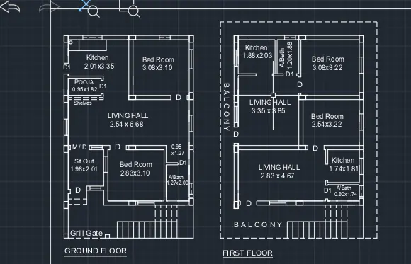
figure shows a plan of g+1 floor according to vastu.
.
let us assume the size of column as 600*600mm
let us assume the height of column as 3.5m
DEAD LOAD OF STRUCTURE:
dead load of column = volume of column* unit weight of concrete
= 0.6*0.6*3.5*25
= 31.5KN.
let us assume the size of beam as 500*500mm.
let us assume the height of beam as 4.5m.
dead load of beam = volume of beam* unit weight of concrete
= 0.5*0.5*4.5*25
= 28.125 KN.
SELF WEIGHT OF SLAB:
let us assume the slab thickness as 250mm.
self weight of slab = slab thickness * unit weight of concrete
= 0.25*25
= 6.25 KN.
LOAD DUE TO BRICK WALL :
assume the wall thickness as 230mm.
brick wall load = 0.23*3.5*20
= 16.1 KN
LIVE LOAD OF STRUCTURE :
as per IS 875 part 2 for residential building:
Living/ Dining - 2Kn/m2
kitchen - 2Kn/m2
bedroom - 2Kn/m2
bathroom - 2kn/m2
storeroom - 2Kn/m2
terrace - 3Kn/m2
WIND LOAD IS CALCULATED USING THE FORMULA :
Pz = 0.6Vz^2
Vz is calculated using formula ,
Vz = Vb*k1*k2*k3*k4
assume the value of Vb as 50m/s and then the value of k1 will be 1 according to the following table.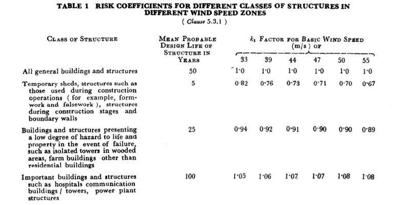
to calculate the value of k2 consider the following table of is 875
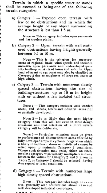
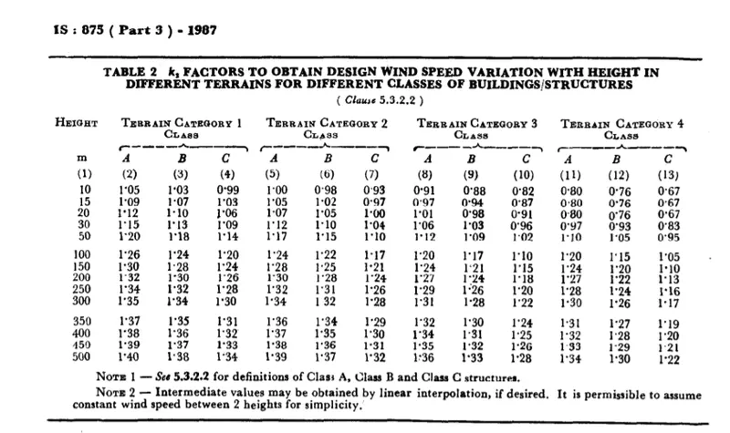
now taking into consideration category 3 we get the value of k2 from the above table as 0.91
now to obtain k3 consider the following table.
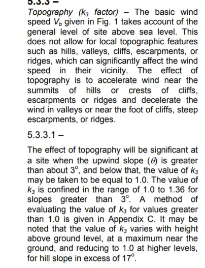
hence the value of k3 will be 1.
now to calculate the value of k4 consider the following table.

value of k4 = 1.15
now substitute all these values ,
Vz = vb *k1*k2*k3*k4
= 50*1*0.91*1*1.15
Vz = 52.325m/s.
Pz = 0.6 Vz^2
= 0.6*52.325^2
Pz = 1642.74m/s