AutoCAD_Sketching and Editing images_Week 3
1ST FIGURE :
AIM : To execute the given figure in autocad.
PROCEDURE :
open the autocad and enter the line command.
enter the length of base which is 3units.
from the end point of first line enter the command as (0,2.12<135) ,
because it is a polar co ordinate.
mark the next line from this point i.e (2.83<90).
take a line of 2 units from this point in the negative x direction and with the
help of close undo command ,complete the figure.
at a distance of 1 unit from bottom draw a circle of radius 0.6, and from a distance of
2.5 from bottom draw another circle of radius 0.4 .
mark the dimensions and complete the figure removing some unnecessary lines with
the help of trim command.
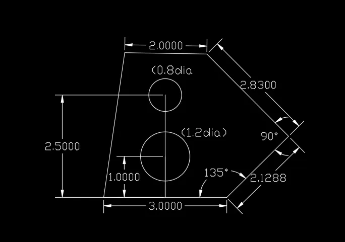
FIGURE 2 :
AIM : To execute the given figure in autocad.
PROCEDURE :
open the autocad and enter the line command.
enter the length of base which is 8 units.
from the left most point of this line draw a vertical line of 1.9, and from this point
enter the command as (@2.1<135) , leave it upto this part, and start from right most point
of the figure by drawing a vertical line of 2.5, and from this point draw a line of 3 units ,
by entering the command as (@3<90) , followed by a line of 2.6 perpendicular to this point .
join the intermediate line between the two points which was left in the fourth point.
mark the dimensions along with angles and complete the figure.
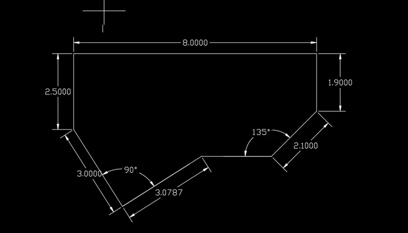
FIGURE 3:
AIM : To execute the given figure in autocad.
PROCEDURE :
open the autocad , enter the line command and enter the length of base line which is 5.01,
from the right most point of this line draw a vertical line of 1.6.
from the left most point of base line ,draw a vertical line of 3.3,
followed by a line of 2.65 in the positive x direction ,
join the intermediate line which was taken from the right point of base line.
draw a circle from the base at a distance of 1.6 of radius 1.6.
complete the figure and mark the dimensions.
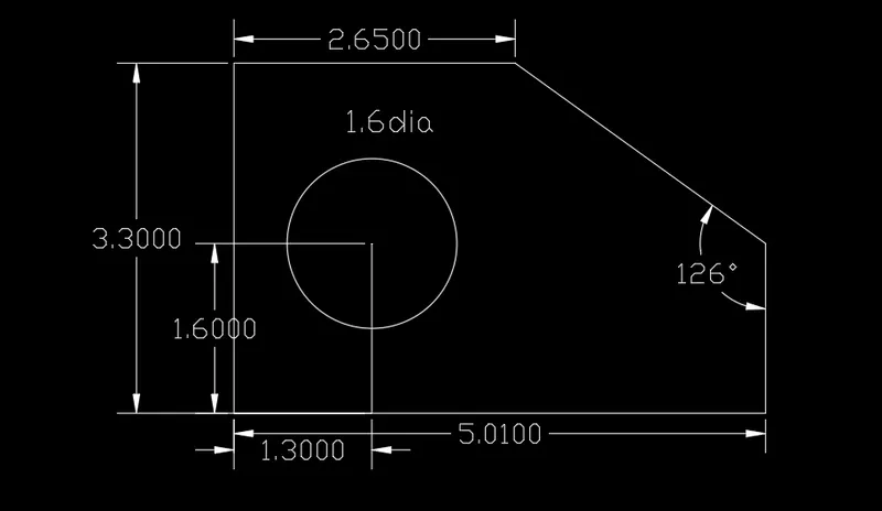
FIGURE 4 :
AIM : To execute the given figure in autocad with the help of autocad.
PROCEDURE :
open the autocad and enter the line command ,draw a base line of 3 units ,followed by a vertical line of
0.5 in the downward direction.
from this point draw a horizontal line of 2.5, followed by a vertical line of 2.5 units.
direct this line to a distance of 2 units in the negative x direction , project a vertical line of 3 units from this point ,
followed a horizontal line of 2.5 units in the negative x direction .
draw a line of 2 units from this point in the downward direction.
join the intermediate line and complete the figure, mark the dimensions.
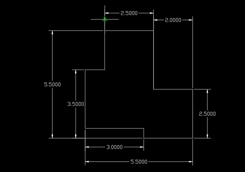
FIGURE 5:
AIM : to execute the given figure in autocad with the help of autocad.
PROCEDURE :
open the autocad and enter the line command.
or with the help of rectangle command , draw a rectangle with the dimensions 11.5*6.
enter the offset command, i.e press o enter, enter the offset distance which is 3 units, from both sides
of rectangle.
place a circle of radius 1.5 exactly at the centre of rectangle, place a pair of concentric circles
on either sides of rectangle of radii 1 and 0.5 units.
drawing circle is done with the help of command , C enter , then enter the radius of circle.
mark the dimensions and complete the figure.
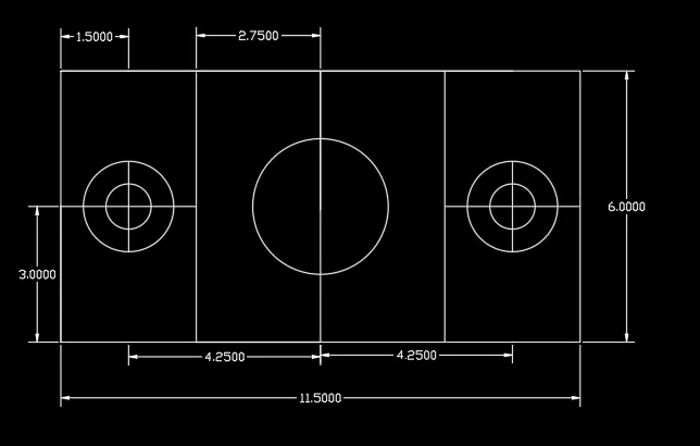
FIGURE 6 :
AIM : To execute the given figure in autocad with the help of autocad.
PROCEDURE :
open the autocad and enter the line command.
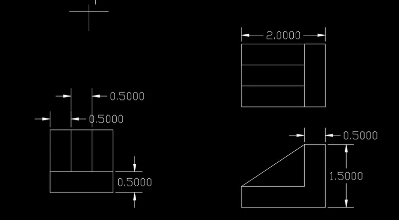
in this sheet, we have to draw a set of three figures.
enter the line command, enter the length of line 1.5, followed by vertical line of length 0.5,
doing this complete the rectangle of 1.5*0.5.
from either sides of rectangle draw a line of 1 units and join the intermediate sides.
take the offset of 0.5 from both the sides which results into a set of three vertical rectangles.
consider the second figure, draw a horizontal line of 2 units and complete a square of 2*2.
take the offset of 0.5 from the left side of square, followed by two horizontal offsets from top and bottom,
it completes the figure, and mark the dimensions.
for the third figure draw a horizontal line of 2 units followed by a vertical line of 1.5 units.
from the previous point draw a horizontal line in the negative x direction of 0.5,
from the first point of the figure, draw a vertical line of 0.5 units, join the the line from this point to the
next point resulting in a triangle, mark the dimensions and complete the figure.
7TH FIGURE :
AIM : to execute the given figure in autocad.
PROCEDURE :
open the autocad and enter the line command and draw a horizontal line of 210 units,
from the right side of this draw a vertical line of 75 units, and from the left side draw a line of 100 units,
enter the rectangle command and create two rectangles of size 70*30, and place them at a distance of 20 units from both the sides,
and 10 units from the vertical, leaving a distance of 30 units in the middle.
create a circle of radius 1.5 by entering the c enter command , and enter the radius which is 1.5.
place this circle at the right bottom portion of the figure.
similarly create a circle of 25 units and place it at left bottom portion of figure.
from both the circles keeping the cursor at the centre of circles and draw an arc by using the arc command,
and then entering the starting point and end point, join the intermediate line between two circles.
fillet the four corners of rectangle, use the command ,f enter, enter the fillet radius ,
and then select the two corner lines which are to be filleted.
mark the dimensions and complete the figure.
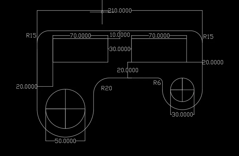
FIGURE 8 :
AIM : to execute the given figure in autocad.
PROCEDURE :
open the autocad and enter the circle command, which is c enter , then enter the radius of circle,
which is 2.5 and 2 units , create a pair of concentric circles,
mark the distance of 4.275 from both the sides of centre.
on both the sides draw a circle of radius 0.9, enter the circle command by pressing c enter,
and then enter the radius, which creates the circle,
from the two circles present at right and left corner , draw an arc on both the sides,
which is obtained by pressing the arc command and then selecting the starting point, end point, direction option
on both the sides, continue the line from arc to the central circle on all the four sides which forms the tangent.
mark the dimensions and complete the figure.
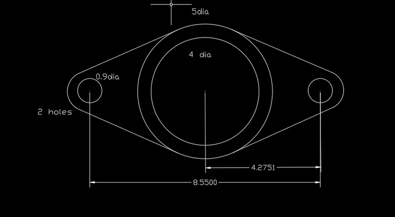
FIGURE 9 :
AIM : to execute the given figure in autocad.
PROCEDURE :
open the autocad and enter the circle command, create a pair of circles of radii 8 and 9 units,
placing their centres at distance of 32.6 units ,
press the c enter command , then enter the radius which creates the circle.
then create a circle of radius 41.8 and place it in such a way that the top portion of the circle ,acts as the arc joining them,
similar way draw another circle of radius 20.10 units and place it in such a way that it acts as the arc joining the bottom
circles , with the help of trim command, erase the remaining lines and complete the figure,
trim command is obtained by pressing t r enter and then click the line you want to trim,
mark the dimensions and complete the figure.
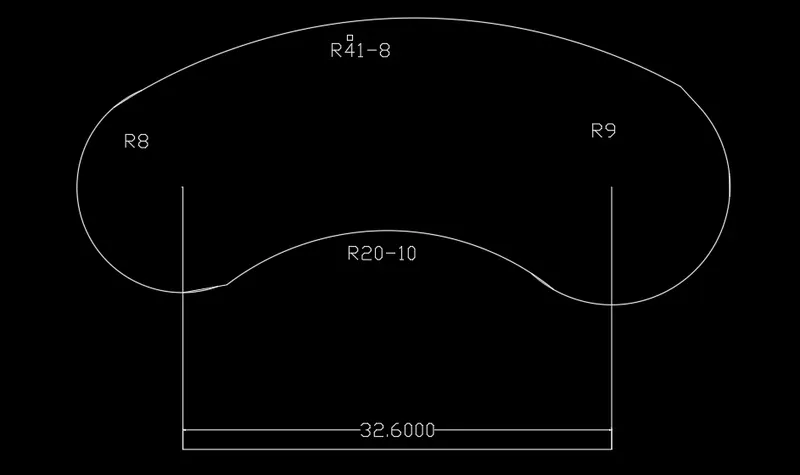
FIGURE 9 :
AIM : to execute the given figure in autocad .
PROCEDURE :
open the autocad and enter the line command.
since there are no dimensions mentioned for this figure, create a square considering your own dimensions,
assume as 10 units each side, then take offset of 1 unit from all the sides,
select the polygon command, enter the number of sides which is 4.
select the option of circumscribed in a circle which results in a polygon,
take the offsets from all the four sides by using o enter command, then entering the length of offset,
place this polygon over the square as shown in figure.
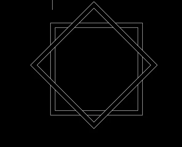
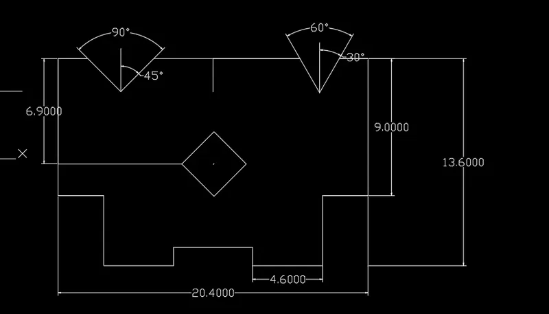
FIGURE 10 :
AIM : to execute the given figure in autocad.
PROCEDURE :
open the autocad and enter the line command by pressing l enter ,
then enter the length of line which is 20.4, draw a vertical line of 9 units from both the sides of this line ,followed by
a horizontal line of 3 units coming towards the centre, then draw a vertical downward line of 4 units on both the sides from
this point, followed by a horizontal line of 4.6 units coming towards centre on both the sides.
then project a vertical line from both the points of assumed dimension and join the intermediate line,
draw a polygon of of 3 units exactly at the centre of figure , such that its left corner is at a distance of
6.9 units from the top. to obtain the above inclined lines need not make use of polar co ordinate everytime.
just select the option '" restrict circle to specified angles " present at the right bottom portion of autocad screen,
select the angle you want to incline the line at, in this case we are selecting the option 30,60 ,90.
enter the line command ,take the line and then drag it in the inclined direction it results in a green line which inclines the line at 30 degree,
from this point repeat the same procedure to obtain the specified angles ,
mark the dimensions and complete the figure.