AutoCAD_Creating Column Schedule and Drawing Template_Week 5
QUESTION 1 :
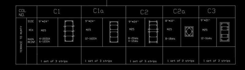
AIM : CREATE A COLUMN SCHEDULE AS SHOWN IN FIGURE.
NOTE : CREATE A COLUMN SCHEDULE WITH THE HELP OF LINES. ALSO INSERT TEXT WITH THE HELP OF DTEXT COMMAND OR SINGLE LINE TEXT.
PROCEDURE :
open the autocad and invoke the rectangle command by pressing rec enter.
draw the rectangle according to assumed dimensions.
draw the vertical and horizontal lines using line command.
make the rows and columns as shown in figure.
write the text in the rows and columns as shown in figure.
top view of columns are given in the figure, draw a rectangle of 9''*24'' and draw lines in it
showing stirrups and draw circles at every corner which represents rods.
for the first figure, draw 10 circles because there are 10 rods,
for the second figure, there are 16 rods ,so draw 16 circles.
for the third figure draw 12 circles and place them as shown in figure.
fourth column dimension is 8''*10' , and there is a diamond ring in it, draw 8 circles.
for the last column ,draw a column of 9''*21', draw 12 circles.
mention the set of stirrups in the last row of every column i.e for the first three columns and last column there is 1 set of 3 strips.
for the fourth column there is1 set of 2 strips.
QUESTION 2 :
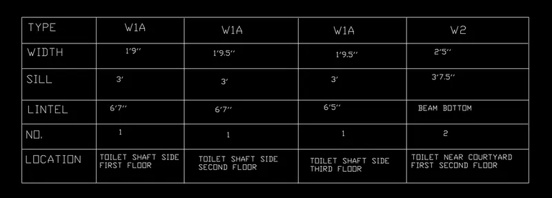
AIM : CREATE A WINDOW SCHEDULE AS SHOWN IN FIGURE.
PROCEDURE :
open the autocad and invoke the rectangle command by pressing rec enter.
draw the rectangle according to assumed dimensions.
draw the vertical and horizontal lines using line command.
make the rows and columns as shown in figure.
write the text in the rows and columns as shown in figure.
there are 6 rows and five columns,
fill the first column with types and width, sill, lintel,number, location.
w1A ,w2 are the different types of windows given, fill the given values in the columns drawn.
Q3):
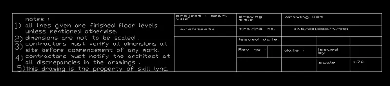
AIM : Create the drawing template as shown in the figure:< Use the Notes as in the figure>
PROCEDURE :
open the autocad and invoke the rectangle command by pressing rec enter.
draw the rectangle according to assumed dimensions.
draw the vertical and horizontal lines using line command.
make the rows and columns as shown in figure.
write the text in the rows and columns as shown in figure.
Q4:
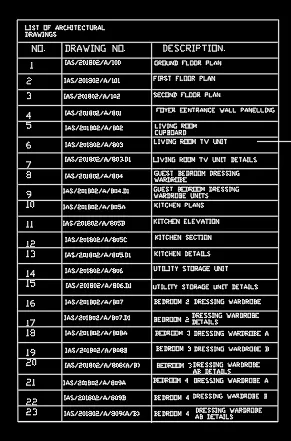
AIM : CREATE THE LIST OF DRAWING SCHEDULE AS SHOWN IN FIGURE.
PROCEDURE :
open the autocad and invoke the rectangle command by pressing rec enter.
draw the rectangle according to assumed dimensions.
draw the vertical and horizontal lines using line command.
make the rows and columns as shown in figure.
write in the top row as list of architectural drawings.
write down the headings in the first row as number, drawing number, description.
write down the different components of the schedule as per the headings.
QUESTION 5:
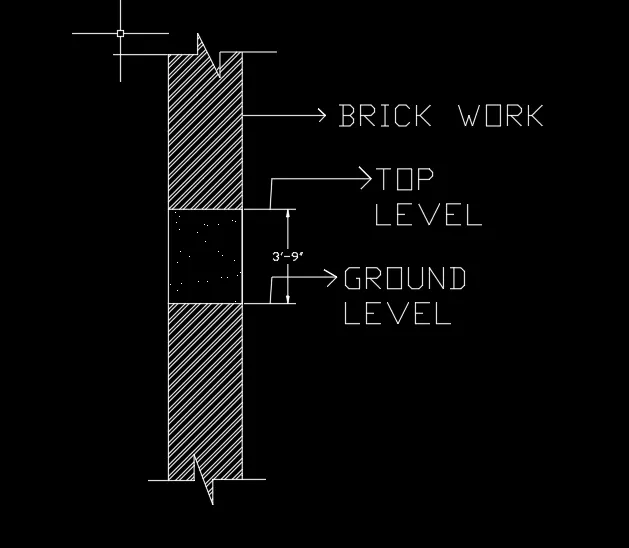
AIM : Create the Beam detail as shown in the figure and provide text for Top level and Ground level wherever given.
PROCEDURE :
open the autocad ,invoke the units command by pressing UN enter.
since a dimension is given in feet ,therefore select the option architectural.
then invoke the line command by pressing L enter, and enter the dimension of vertical line
which is 3'9'' , followed by a horizontal line of assumed dimension and complete the rectangle,
project the lines from this rectangle in both top and bottom and create a figure as shown.
hatch the obtained portion by pressing H enter command, pick point to be hatched
and select the hatch type from the ribbon tab and select the portion ,it will be hatched.
mark the top portion of the figure as brick work and the middle portion as top level and bottom level.
mark the dimension of 3'9'' and complete the figure.