Assignment 7-Side Pole Crash Simulation Challenge
Objective: To perform the side crash analysis on the given model.
- Check unit system and either follow [Mg mm s] or [Kg mm ms].
- Create an appropriate interface, friction 0.2 and recommended parameters.
- Make sure of no penetration and intersections.
- Create a rigid wall with friction 0.1 as per the reference model.
- Compare the model weight with the reference model and use added masses to reach the target weight of 700kg while getting CG about the required range.
- Initial velocity as shown in the picture.
- Use a model checker to ensure good quality.
- Timestep :0.5 to 0.1 microseconds.
- Run 80ms.
Output requests:
- Sectional force in the cross member.
- The intrusion at B pillar, hinge pillar and fuel tank region. Provide recommendation on what can help to reduce Fuel tank intrusion.
- Peak velocity of an inner node of the door.
Procedure:
- Open the hypermesh software and select the profile as Radioss.
- Import the given model with the help of an option Import Solver deck present at the top in the menu bar.
- After importing the model start working on the model within the given parameters.
- open the hyper crash application from the hypermesh software and check the unit system.
- The unit system used Hypercrash is KN MM MS KG
- Upon opening the hyper crash application import the same model which has been imported into the hypermesh software.
- After opening the given model in both the applications try to work on the model.
- In Hypermesh, create a rigid wall for the given model by using the solver browser, In the solver browser, right-click and select CREATE and from the options select the RWALL which is at the bottom and select the CYLINDRICAL type.
- After creating a Rigid wall, click on it & in the status bar enter the details of various parameters like Diameter, D search, Friction etc. and select the node where we should need the Rigid wall and after entering all the values the RWALL is created on the graphic area. Check on the created RWALL and make corrections if needed.
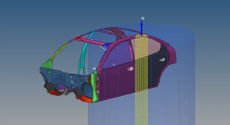
CYLINDRICAL RIGID WALL CREATED WITH DIAMETER 254MM
- Create an INIVEL card which means an initial velocity is given for the model. In the solver browser, right-click and select the create and from the options select the boundary conditions at the top and from the list select the INIVEL card.
- After creating the INIVEL card select the card in the solver browser and in the status bar enter the details of various parameters like Vx, Vy, Vz and select the whole components. In the Vy, this means velocity in the Y-direction enter the value as 15.34 and in the rest of the directions keep it as 0 which means in Vx and Vz.
- Scroll down in the status bar, in the Grnod_id option, select and right-click and select the create option and a window will pop up in the graphic area in that select the option called entity id in that change the option from nodes to components with the help of dropdown options and select all the 95 components on the screen and click OK and close the window.
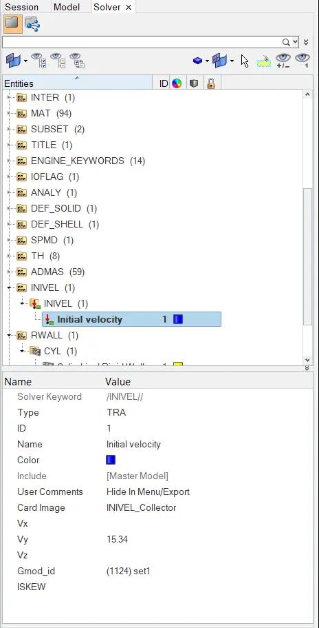
AN INIVEL CARD CREATED WITH VELOCITY IN Y-DIRECTION
- Create the output blocks for the intrusions on the hinge pillar, b-pillar and for the fuel tank and also create an output block for the peak velocity. Before creating the output blocks create skews for the four output blocks.
- To create a Skew, in the solver browser right-click and select the create option and scroll down to the bottom and select the SKEW card in that select the MOVING SKEW. Select the SKEW card and down in the panel area to select the option Create by node reference and select the origin node first and then select the node for the X-axis and then select the node for XY plane overall select the 3 nodes in order to create a SKEW which means a coordinate system. Complete this whole process of creating a SKEW on the component which is exactly opposite to the fuel tank.
- Follow this same process of creating the skew for the hinge pillar and B-pillar. But for the peak velocity creating the skew on the inner door which is going to collide with the cylindrical rigid wall.
- After creating the SKEW card go back to the fuel tank output block that has been created and in the status bar select the NODE_Id and select the node which is on the opposite end of the fuel tank for the skew we created. Do not select the node for the same component which we created for the skew and for the SKEW select the coordinate system which we have created which means SKEW.
- Repeat the same process for the hinge pillar, B-pillar. First by creating a SKEW and by selecting a NODE_Id followed by selecting a system which means the SKEW. but for the peak velocity select the same node which is created for the skew on the same component.
- Assign all 4 components for the 4 output blocks with the skew systems.
- Create a Type 7 interface for the model in the solver browser. In the solver browser, right-click and select the create from the list of options select the INTER and in that select the TYPE 7 Interface. Click on the Type 7 Interface in the solver browser, and in the status bar enter the recommended values for various parameters and also select the slave and master entities. After creating the type 7 interface, delete the various other interfaces which are of no use.
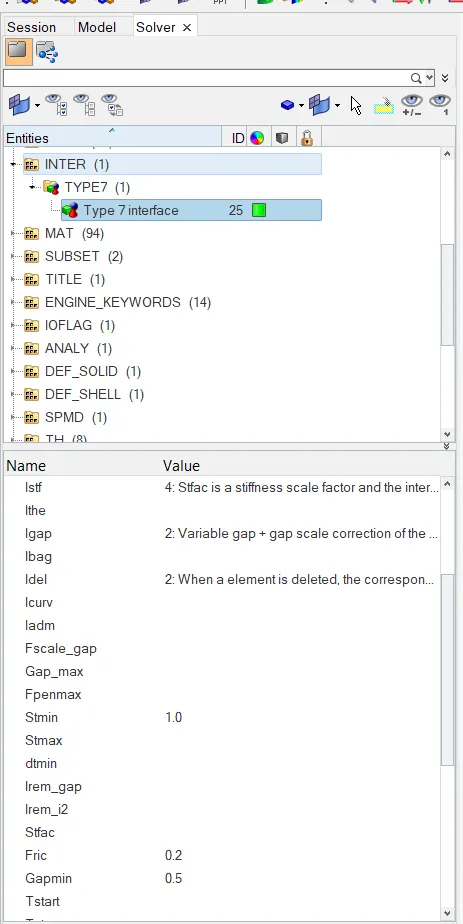
TYPE 7 INTERFACE IS CREATED
-
Add the mass to the given model, the mass value given for the model is 700kg. To add the mass in the solver browser select the add mass card and right-click and click on the Create for a new add mass card.
- After creating an Add mass card, select the newly created add mass card in the solver browser. In the status bar, enter the value of mass in the Mass option as 1KG and select the option MassType and select the first option and in the grnd_ID option select and right-click and in the Entity ID select the nodes by using box selection on the cross rails.
- Select the no of nodes needed to attain the 700kg mass. After selecting the nodes click on the close button to close the subwindow.
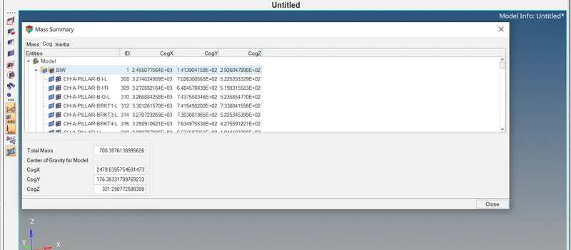
THE MASS IS ADDED UPTO 700KG
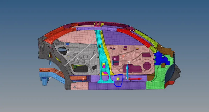
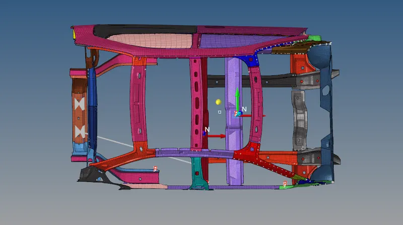
THE COG POINT IN THE MIDDLE OF THE CROSS RAILS
- Make sure to bring the COG point to the centre of the cross rail in order to maintain the balance. After adding the mass to the model, create the cross-sections on the model which are given with the question.
- Create a sectional force for the TWO CROSS RAILS to create a section in the solver browser right-click and select the create option and scroll down to the bottom and select the SECT card. After creating the SECTION card and rename it as RAIL 1.
-
Before doing all this, create a FRAME for the cross-section in the same way as we created the SKEW.
-
After creating the FRAME select the RAIL-1 cross-section and in the status bar enter the details for the various parameters and in the GRSHELL Id select two rows of elements on the RAIL-1 and in the Iframe select option - 12 the COG of the section and also enter the values for the deltaT as 0.1 and for the Alpha as 1.94.
-
Following the same process as we did for RAIL-1, create section force for RAIL-2.
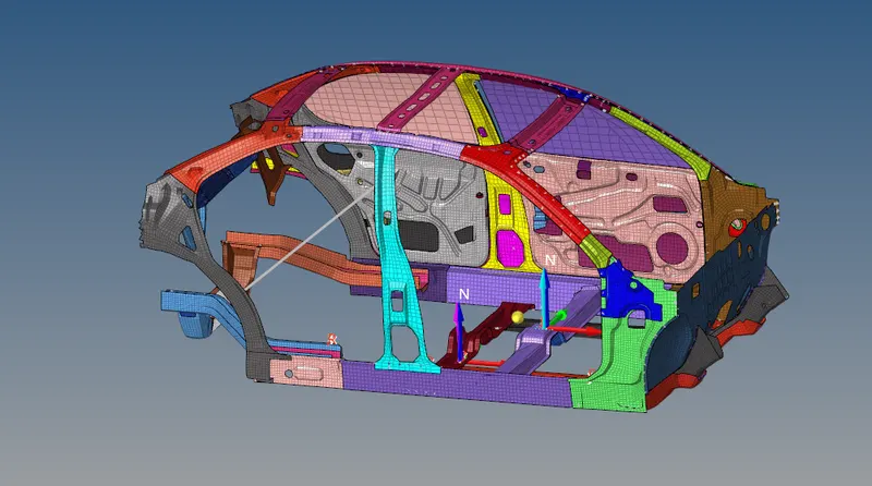
2 CROSS-SECTIONS SHOWED ON THE 2 CROSS RAILS (MAROON & VIOLET COLOUR)
- After creating all this, create an Output Block in the model browser and name it as Cross-sections. Select the Output Block and in the status bar, assign the 2 cross-sections in the Output Block.
- After creating all this, export the file to a folder on the computer. Import the exported file to the Hypercrash application. After importing the file, click on the Quality on the top of the window and select the model checker from the given options.
- In the model checker browser, it shows some errors and warnings for the model, clear the errors manually one by one. After clearing the errors export the file and to the specified folder by using the file option at the top of the menu and click export in that and select the Radioss option, a pop window will appear on the screen in order to export the model select the folder you want to export the model and click on the OK button.
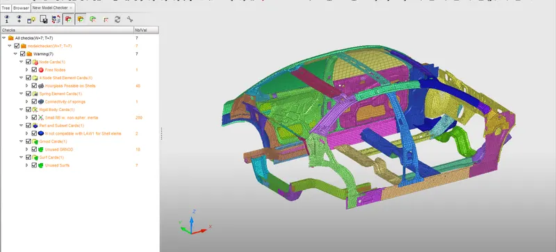
MODEL CHECKER SHOWS ERRORS AND WARNINGS IN A SEPERATE BROWSER IN HYPERCRASH
- After Exporting the model to a specified folder, import the model in the Hypermesh application and run the model.
- Click on the Analysis on the tool panel and select the Radioss tool from the available tools. After entering into the Radioss tool, select a specific folder to save the model and check in the options enter the value as -nt 4, click on the include connectors option and after selecting all these options click on the Radioss button to run the simulation.
- Open the Hyperview application to look at the simulation of the model. By using the load model option select the .h3d file from the results.
- After opening the neon side.h3d file, click on the Apply button present in the bottom corner in order to view the simulation.
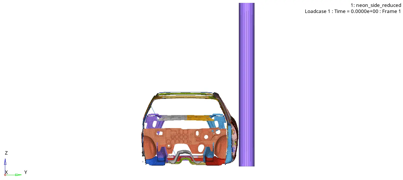
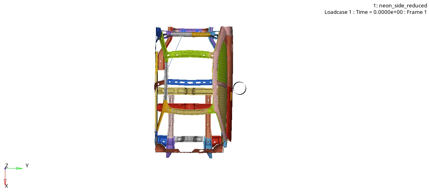
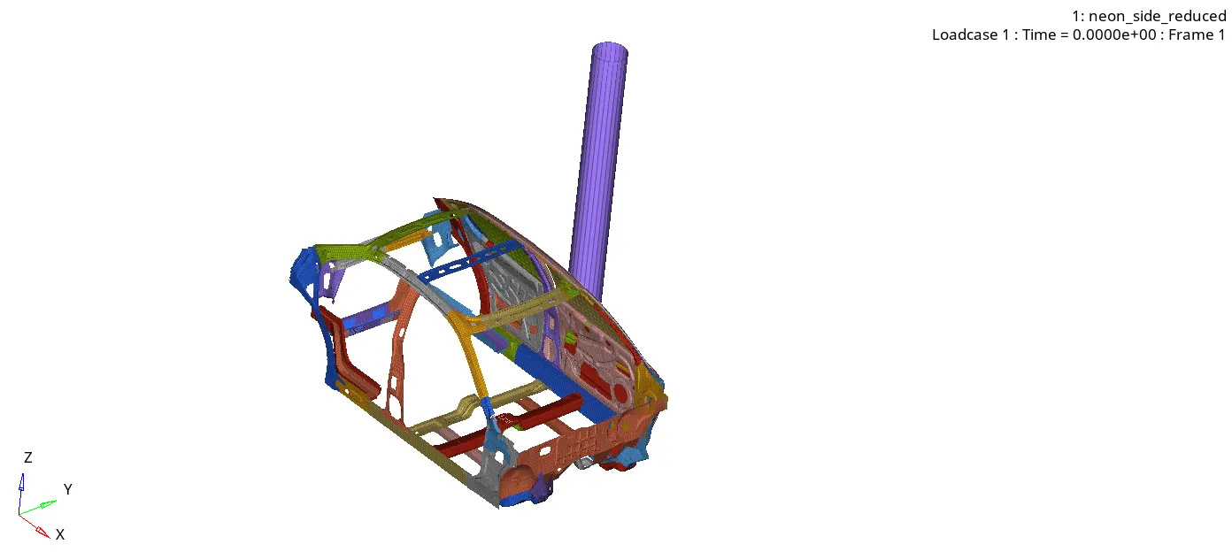
NEON_CAR MODEL SIDE CRASH SIMULATION IN HYPERVIEW APPLICATION
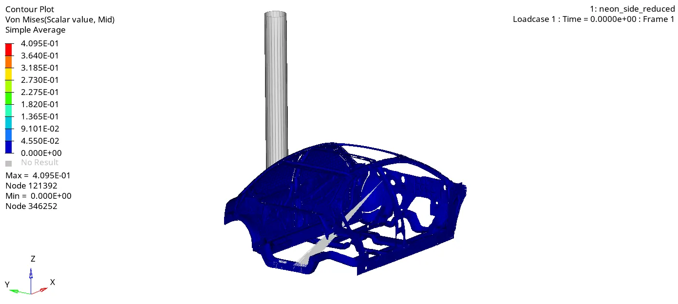
VON-MISES STRESS CONTOUR OF THE CRASH SIMULATION
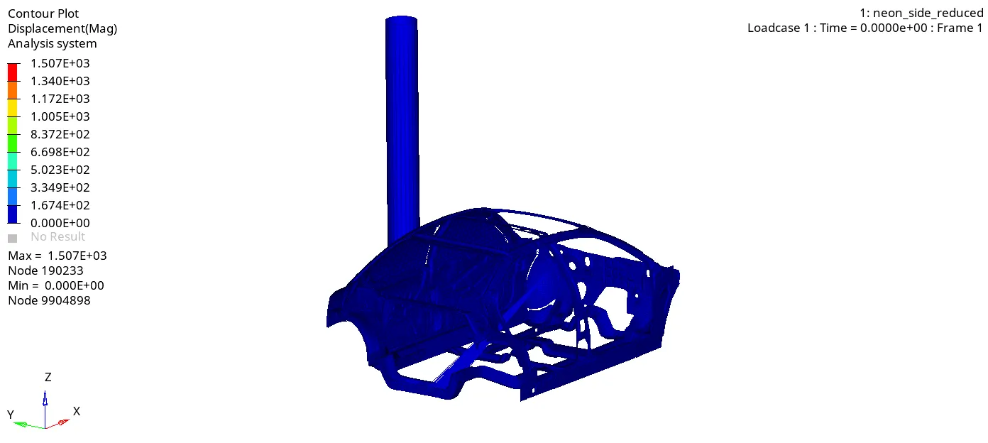
DISPLACEMENT CONTOUR OF THE CRASH SIMULATION
- The energy error is -3.3% so the crash phenomena which is acceptable. The mass error is 0.1101E-01 and the total number of cycles is 80000. These are the values that are obtained from 0001.out file.
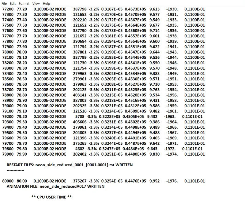
ENERGY ERROR AND MASS ERROR VALUES FROM THE.OUT FILE
- After looking at the simulation open the HyperGraph application in order to plot the Results of various energy parameters.
-
In the X type subcase select the Time, in the Y type subcase select the Global Variables, in the Y request select the Internal energy and in the Y component select the MAG option and then click on the apply button.
- Open the HyperGraph application, in the Data file option click on the file icon, select and open the neon_side_reduced T01 file present in the saved folder during the analysis in the hypermesh in order to plot the results.
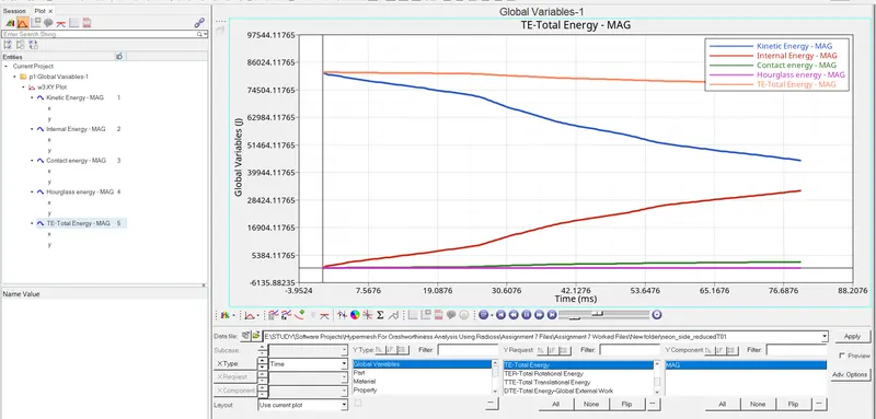
The total energy is 85000 Joules remains stable throughout the analysis. When a car moves there is a kinetic energy and it decreases when it hits the rigid pole. The internal energy rises to 31000 Joules up to 80ms. Some of the energy gets dissipated during the crash.
Contact energy and Hourglass energy are negligible.
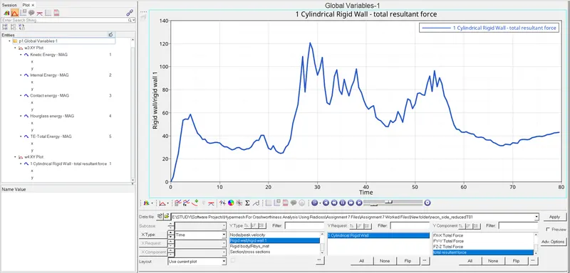
The Rigid wall force reaches a peak up to 120KN during the 28ms of the simulation.
The intrusions acting on the Fuel tank, B-pillar and the Hinge pillar. These regions are more important for the safety of the passengers during the crash.
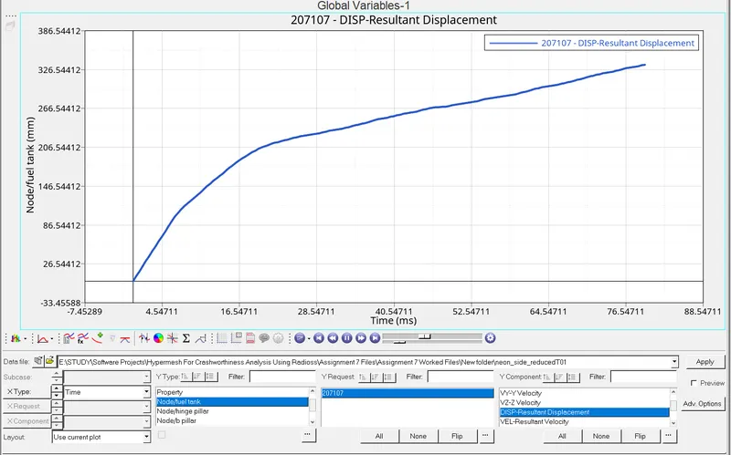
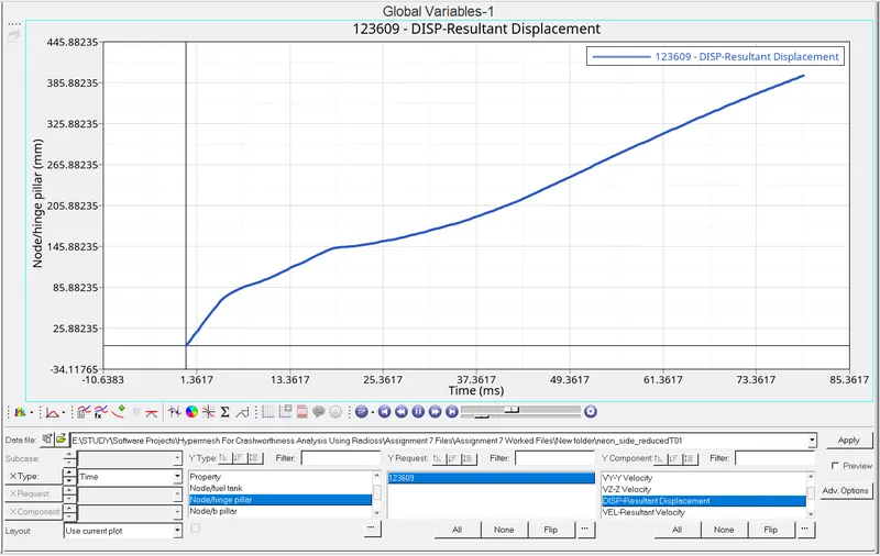
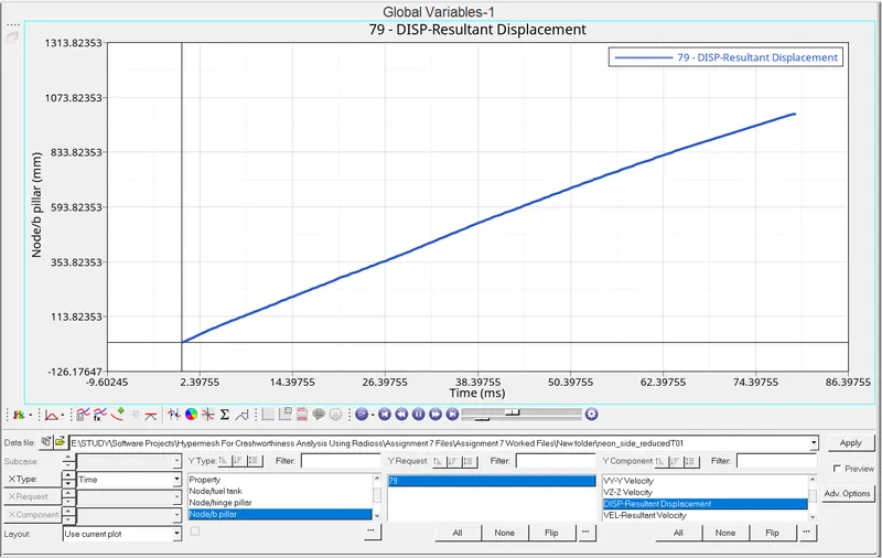
The displacements on the 3 intrusion points are taken into account separately and are measured.
From the above graph, we can see the intrusion points are noted
- The maximum intrusion that occurred at the fuel tank region is 326.54mm.
- The maximum intrusion that occurred at the hinge pillar region is 400.56 mm.
- The maximum intrusion that occurred at the B-pillar region is 1017.56 mm
The peak velocity acting on the inner door is measured.
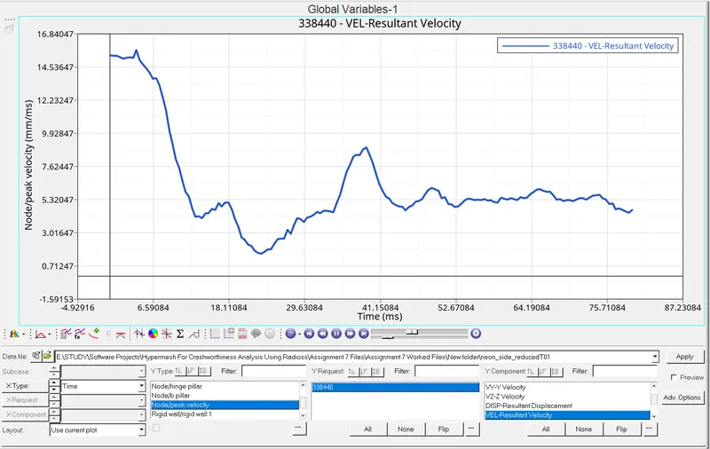
The velocity on the inner door is measured and the peak velocity attains on the inner door at 5ms and there is the fluctuation of velocity throughout the end of the simulation.
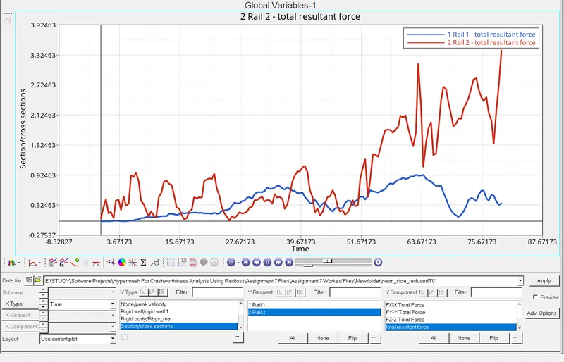
The cross rails play an important role during the crash from the side. From the observation, we can see that cross rail 1 has more stiffness than cross rail 2.
The total resultant force for the cross rail 1 is 0.8KN.
The total resultant force for the cross rail 2 is 3.5KN.
Conclusion:
- There are no errors shown in the model checker browser in the Hypercrash application.
- The energy error and mass error obtained are in an acceptable range.
- The cross-sections are created and assigned to the output block in the model tab. The graphs have been plotted.
- The intrusions created for the B-pillar, hinge pillar and fuel tank region. The graphs have been plotted for the intrusions.
- The peak velocity attained during the simulation is at 5ms.