Assignment 7- Side impact test on Neon car BIW component according to FMVSS 214 standard Rigid Pole Side Impact Test in RADIOSS
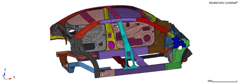
OBJECTIVE:- To perform a side crash test analysis on the BIW component and obtained required plots for the output requests.
Side crash- BIW
- Check unit system and either follow [Mg mm s] or [Kg mm ms].
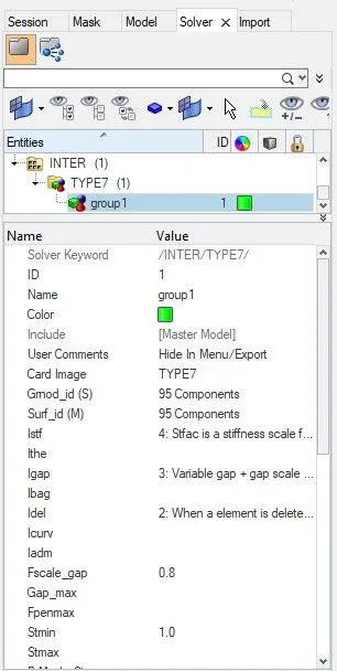
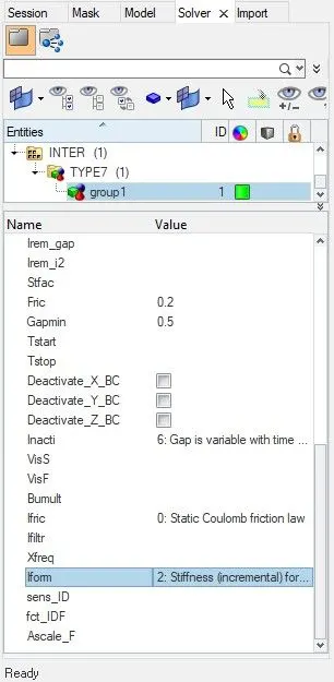
- Create an appropriate interface, friction 0.2 and recommended parameters.
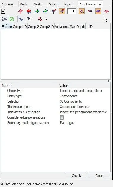
- Make sure of no penetration and intersections.
- Create a rigid wall with friction 0.1 as per reference model.
- Compare the model weight with the reference model and use added masses to reach target weight 700kg while getting CG about the required range.
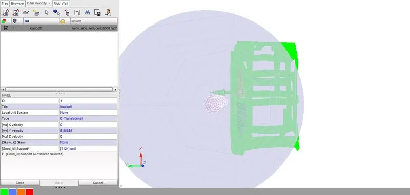
- Initial velocity as shown in the picture.
- Use model checker to ensure good quality.
- Timestep: 5 to 1 ms
- Run 80 ms.
Output requests:
- Sectional force in the cross member.
- Intrusion at B pillar, hinge pillar and fuel tank region. Provide recommendation on what can help to reduce Fuel tank intrusion.
- Peak velocity of the inner node of the door.
Procedure:-
1- Check unit system and either follow [Mg mm s] or [Kg mm ms].
- Open the neon_side_reduced_0000.rad file via notepad.

2- Create an appropriate interface, friction 0.2 and recommended parameters.
- Open HyperMesh and load the neon_side_reduced_0000.rad file via import.
- To create an interface, first open solver tab then right-click -> create -> inter -> Type7, provide the recommended properties.
3- Make sure of no penetration and intersections.
- To check penetration and intersection, in HyperMesh menubar goto Tools -> Penetration Check -> Enity Type= Component -> Selection= Select all the component -> Check
- There should be zero collision and intersection.
4- Create a rigid wall with friction 0.1 as per reference model.
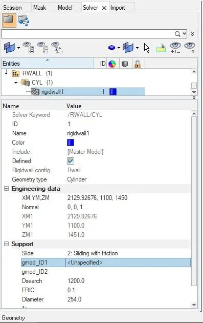
- To create a rigid wall, in solver tab -> right-click to create -> RWALL -> CYL -> provide recommended values
- According to FMVSS Rigid Pole Side Impact Test Requirements, the impact face of the rigid pole shall be a vertically oriented metal structure with a diameter of
254 mm ± 3 mm.
5- Compare the model weight with the reference model and use added masses to reach target weight 700kg while getting CG about the required range.
- Open a HyperCrash window, set the unit to kN, mm, ms, kg, and open the neon_side_reduced_0000.rad file via import.
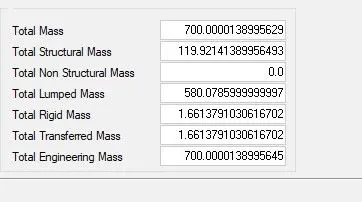
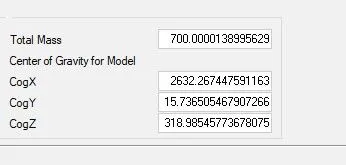
- The mass and CoG of the model can be obtained by in the menubar -> Mass -> Balancing.
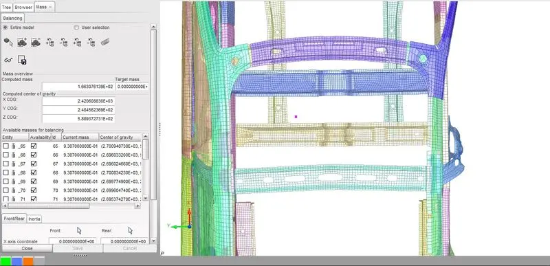
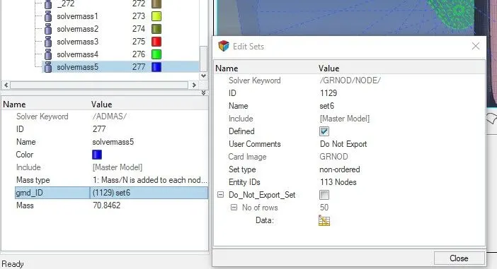
- To obtain the target the mass of 700 kg while maintaining the CoG at the required position, under menubar goto LoadCase -> added mass -> Create a new -> Type 1 -> give MASS and grnod_id while adding mass also check in the mass balancing tab for the total mass and the CoG. Once the target of 700 kg is achieved with the desired CoG point in hypermesh choose the same node and same mass value to attain the target mass and CoG in the required range.
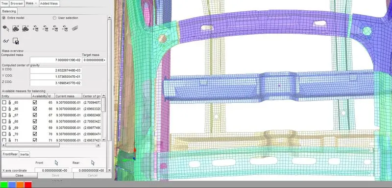
- To add mass in HyperMesh, in solver tab right-click to create -> ADMAS -> Mass type= 1 -> Provide the mass value -> grnd_ID= right-click to create, in the Create Sets choose the Entity IDs which is as nodes, select the required the nodes in the graphics -> Proceed. Similarly, add all the mass of values and position similar to the one created in HyperCrash.
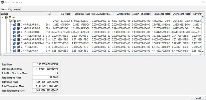
- After adding the mass the position of the CoG in HyperMesh can be compared with the position in HyperCrash, the position should be near to the value and it can be checked by in the menubar under Tools -> Mass Details -> Mass, CoG and Inertia.
6- Initial velocity
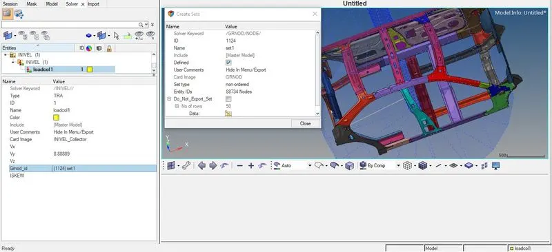
- According to the FMVSS- Rigid Pole Side Impact Test Requirements, the initial velocity of the vehicle should be 32 km/hr.
- So to convert the 32 kmph to mm/s -> Divide the speed value 32 kmph by 3.6 = 8.88889 mm/millisecond.
- To apply the initial velocity, in the solver tab -> right click to create -> BOUNDARY CONDITIONS -> INVEL -> Type= Translation -> Vy= 8.88889 -> Grnod_id= right-click to create, in Create set choose entity id to nodes and select all the displayed nodes on the screen and click on Proceed.
7- Timestep= 5 to 1 ms and Run= 80 ms
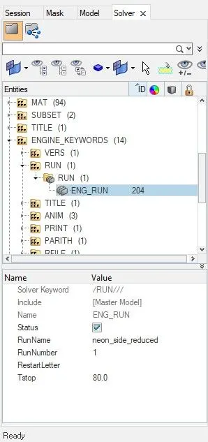
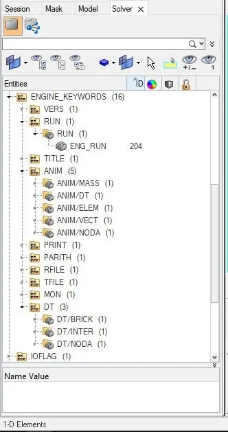
- For Run time in solver tab, goto to ENGINE_KEYWORDS -> RUN -> ENG_RUN -> Tstop= 80 ms
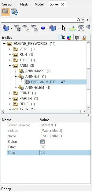
- For Time-step in solver tab, goto to ENGINE_KEYWORDS -> ANIM -> ANIM/DT -> ENG_ANIM_DT -> Tfreq= 2.0 ms
- That mean the number of frames generated will be 80/2= 40 frames.
8- Create the Sectional Force at the cross member.
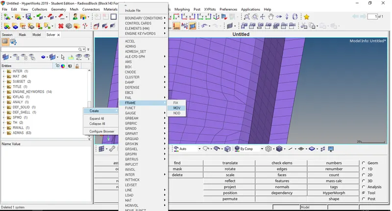
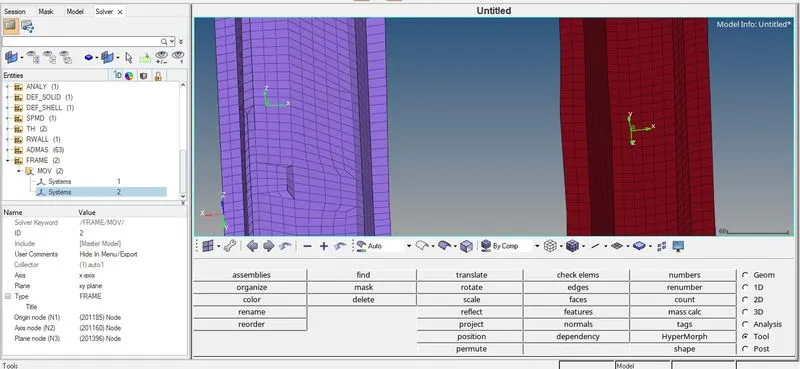
- Before creating the section, first of all, Frame must be generated for that by, in the solver tab right-click to create -> Frame -> Mov -> Create node by reference -> Provide the node for Origin, Axis and plane -> Create. The frames were created for cross member component named "CH-CBN-SEAT-REINF-FT" and "CH-RAILS-U-MID".
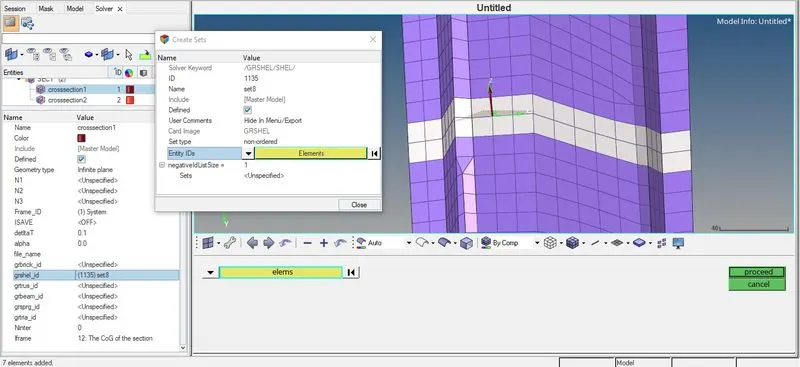
- After creating the Frame, create the sectional force by in solver tab right-click to create -> sect -> sect -> Frame_ID= choose the frame created -> deltaT= 0.1 -> alpha= 0 -> Iframe= 12 -> grshel_id= right-click to create, in the create sets choose entity elements along the strip -> proceed. Repeat this step for all the crossectional part.
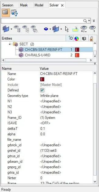
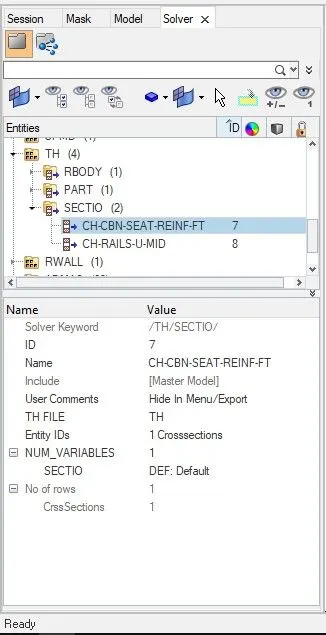
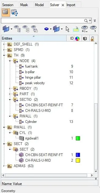
- After creating the section, the output request of the frame can be called by in the solver tab right-click to create -> TH -> SECTIO -> Entity IDs= select the respective crosssection from the created in the crosssection -> NUM_VARIABLES= 1. Similarly, create the output request of all the created crosssection above.
9- Intrusion at B pillar, hinge pillar and fuel tank region.
- Create intrusion by creating spring.
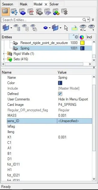
- First, create a property card for the spring by in the model tab right-click to create -> property -> Card Image= P4_SPRING -> Mass= 0.001 -> K1= 0.001
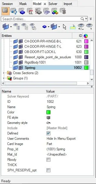
- After creating a property card, in the model tab right-click to create a component and name it Spring and assign the property id as the Spring property just created also the Card Image= Part.
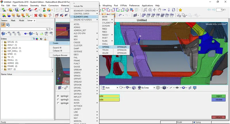
- Now in the Solver tab right-click to create -> ELEMENTS (HM) -> SPRING -> SPRING2N -> Select the 2 nodes to create the spring element, create spring element for the fuel tank, b-pillar and hinge pillar.
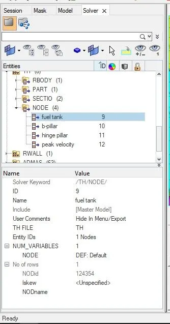
- Now after representing the three intrusions via spring, create an output request by in the solver tab right-click to create -> TH -> Node -> Entity id= select the respective node where the intrusion is to be measured -> NUM_VARIABLES= 1.
10- Peak velocity of the inner node of the door.
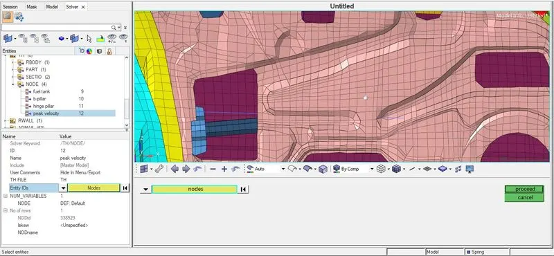
- To measure the peak velocity at the inner node of the door, in the solver tab right-click to create -> TH -> NODE -> Entit id= Select a node from the inner door component -> NUM_VARIABLES= 1.
11- Use model checker to ensure good quality.
- Save the model via export as a RADIOSS file
- Open HyperCrash and load the recently saved file via File -> Import -> RADIOSS
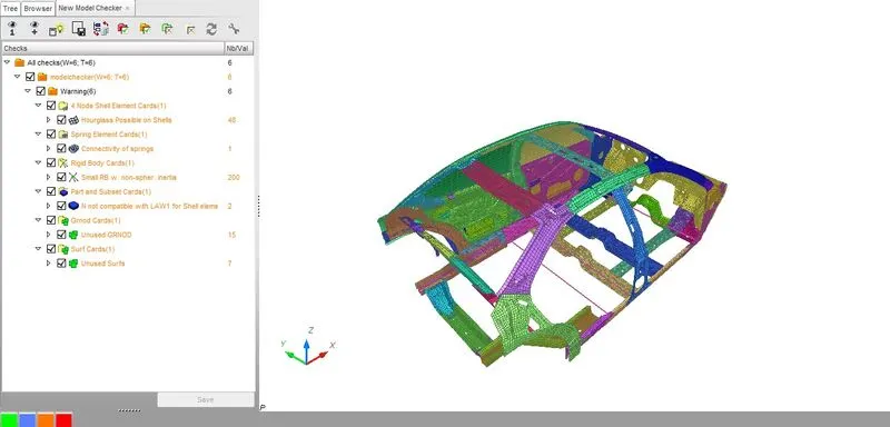
- To check the model, in the menu bar goto Quality -> Model Checker -> RUN, if any error found it should be corrected in the hypermesh for ease of finding error HyperCrash is used.
- After resolving all the error and before going into simulation check the ENGINE_KEYWORDS and Time history for all the required files are correctly mentioned.
12- Analysis
- Save the file via Export as a RADIOSS file, then in a new session open the neon_side_reduced_0000.rad saved file via import in HyperMesh.
- For analysis goto Analysis -> RADIOSS -> choose the path to save -> option= -nt 4 -> RADIOSS

- After completion of the analysis open the file location and open the obtained engine file neon_side_reduced_0001.out via notepad.
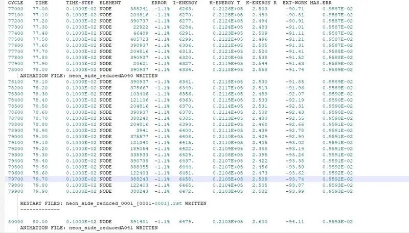
| CASE | Number Of Cycles | Energy Error (%) | Mass Error (%) | Simulation Time (sec) |
| neon_side_reduced | 80000 | -1.1 | 0.9593E-02 | 4023.06 |
Output Files:-
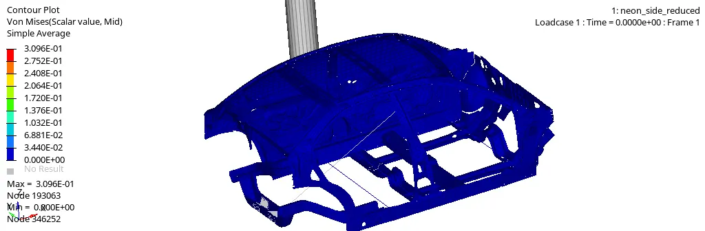
1) Von Mises
- After running Radioss, open hyperview and load the h3d file obtained, the Von-Mises contour plot can be obtained by select "Contour" -> Result type = Von Mises(s) -> Averaging method = simple -> Apply.
2) Global Energy
- To obtain the required graphs split the GUI and from "client selector" select HyperGraph 2D and in the data file load the T01 file obtained from simulation also for X type= time, Y type = Global variables, Y request = Internal energy, Kinetic energy, Hourglass energy, Total energy, y component = MAG and click on apply.
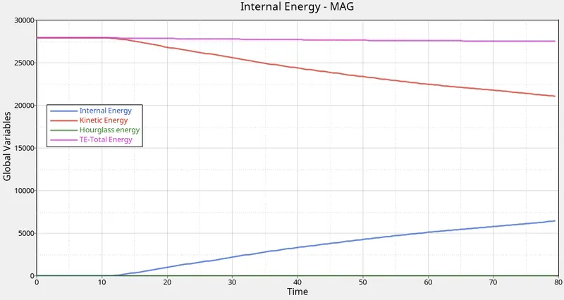
- As the Kinetic energy decreases the Internal energy increases and it can be observed that after 80 ms duration also both have not reached their peak values. The total energy remains constant.
3) Rigid wall
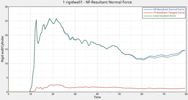
- For the rigid wall forces graphs, X type= time, Y type = Rigid wall/TH_RW, Y request = 1 rigidwall, Y component= NF, TF and total resultant force and click on apply.
4) Contact Energy
- For contact energy graph, X type= time, Y type = Global variables, Y request = Contact energy, y component = MAG and click on apply.
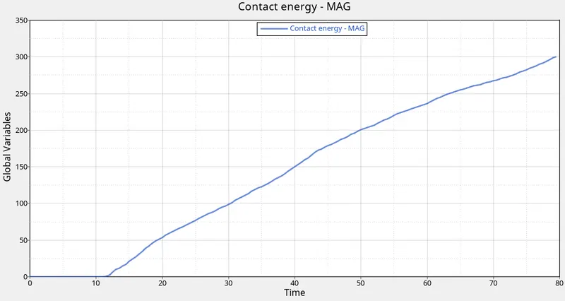
- For the first 10 ms the contact energy is 0 as the component is not in contact with the pole but after the contact the graph increases.
5) Sectional force at the cross member
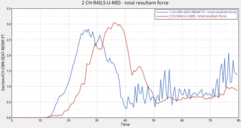
- For the sectional energy graph, X type= Time, Y type= Section/CH-CBN-SAT-REINF-FT and CH-RAILS-U-MID, Y request= 1 CH-CBN-SAT-REINF-FT and 2 CH-RAILS-U-MID, Y component= total resultant force.
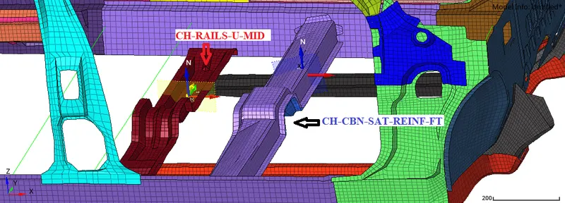
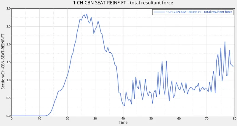
- The peak force observed is 2.84433 kN for the CH-CBN-SAT-REINF-FT section.
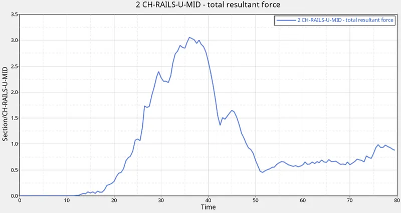
- The peak force observed is 3.054 kN for the CH-RAILS-U-MID section.
6) Intrusion at B pillar, hinge pillar and fuel tank region.
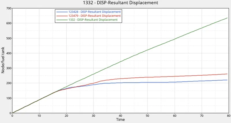
- For the axial force graph, X type= Time, Y type= Node/fuel-tank, b-pillar and hinge pillar, Y request= 123428, 123479 and 1332, Y component= DISP-Resultant Displacement
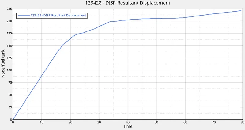
- The intrusion for the fuel tank observed is 221.115 mm.
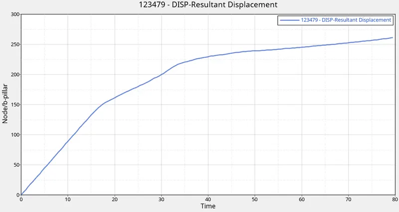
- The intrusion for the b-pillar observed is 261.188 mm.
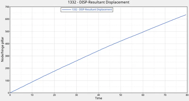
- The intrusion for the hinge pillar observed is 635.771 mm.
7) Peak velocity of the inner node of the door
- For the axial force graph, X type= Time, Y type= Node/Peak velocity, Y request= 338523, Y component= VEL-Resultant Velocity.
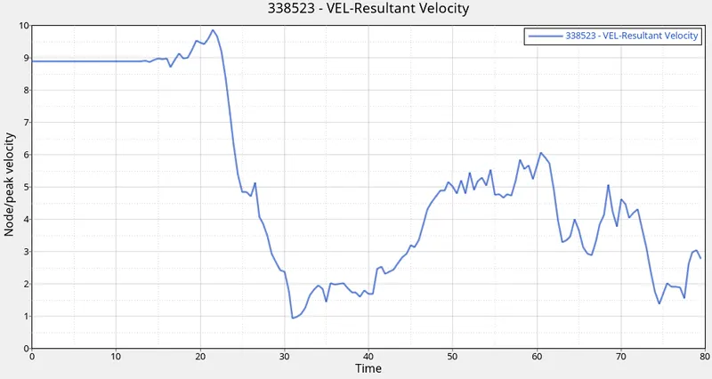
- The highest peak velocity reached is 9.855 mm/ms.
RESULT-
- From the sectional force of the 2 cross member, the CH-RAILS-U-MID observed the highest amount of forces.
- The intrusion at the hinge pillar is maximum in comparison to the fuel tank and the b-pillar.
- By introducing a cross member in the region of fuel tank the intrusion can be reduced.
CONCLUSION-
So by completing this challenge the side crash test analysis on the BIW component of the Neon reduced model is performed using RADIOSS soler and obtained the required outcomes like forces at the cross-section, intrusion at the fuel tank, b-pillar and the hinge pillar and peak velocity ate the inner node of the door.