Assignment 6-Frontal Crash Simulation Challenge
Frontal Crash Test
AIM:
Frontal car crash simulation of Dodge Neon BIW using RADIOSS solver and Preprocessing using HyperMesh / HyperCrash.
OBJECTIVE:
The following are the requirements for this project:
- Set the model of the Neon Dodge ie, the FEA model, so that the required output requests can be post-processed from it.
- Sectional force in the rails at the location of indicated node 174247.
- The axial force received on the rails from the bumper.
- Shotgun cross-sectional forces.
- A pillar cross-section.
- Acceleration curve received on the accelerometer at base of B pillar (on B pillar rocker).
- Intrusions on the dash wall 66695, 66244.
SETUP REQUESTS:
- Check the unit system and either follow [Mg mm s] or [Kg mm ms].
- Create an appropriate interface, friction 0.2, and recommended parameters.
- Make sure of no penetrations and intersections.
- Correct rigid bodies if any issues.
- Create a rigid wall with friction 0.1.
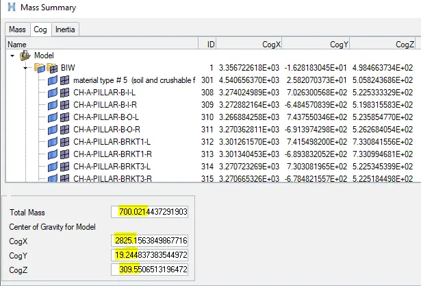
- Compare the model weight with the full-scale 300k nodes model and use added masses to reach the target weight of 700kg while getting CG about the required range.
- Initial velocity 35 mph.
- Use a model checker to ensure good quality.
- Time-step: 0.5 to 0.1 microseconds.
- Run 80 ms
OUTPUT REQUESTS:
- Sectional force in the rails at the location of indicated node 174247.
- The axial force received on the rails from the bumper.
- Shotgun cross-sectional forces.
- A pillar cross-section.
- Acceleration curve received on the accelerometer at base of B pillar (on B pillar rocker).
- Intrusions on the dash wall 66695, 66244.
PROCEDURE:
Import the model:
Import the '.rad' starter file of the model,' neon_front_0000.rad' in Radioss using Import Solver Deck option.
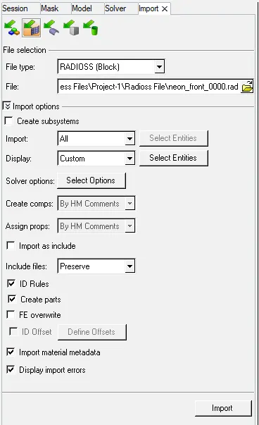
Check unit system and either follow[Mg mm s] or [Kg mm ms].
Unit System: For units, browse Model -> Cards -> BEGIN_CARD
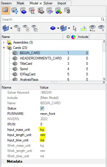
Mass unit : kg
Length unit : mm
Time unit : ms
Make sure of no penetrations and intersection.
For intersecton and penetration
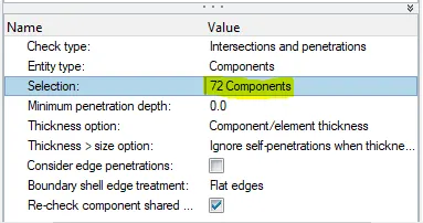
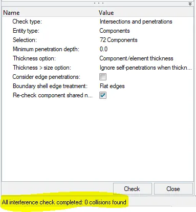
Zero penetration or intersections found
Compare the model weight with the full scale 300k nodes model and use added masses to reach target weight 700kg while getting CG about the required range.
Reach the target weight of 700 kg while getting CG about the required range:
- To compare the model weight with the full scale 300k nodes model and use added masses to reach target weight 700kg while getting CG about the required range.
- Check by using Tools -> Mass Details -> Mass, cog and inertia and check the mass.
Existing weight of mesh geometry: 188 kg
Required weight : 700 kg
Additional mass to be added: 512 kg
To add additional weight to achive the required weight ,
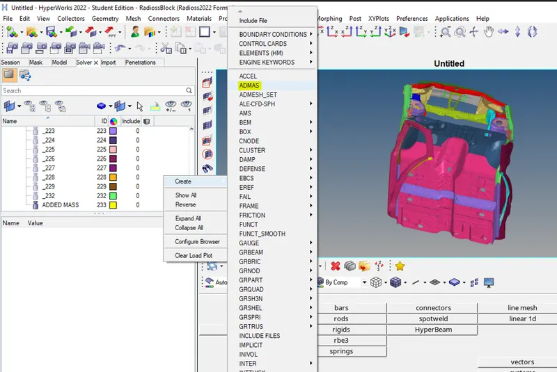
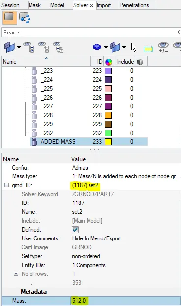
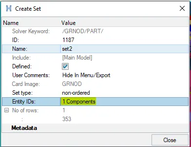
- Go to solver and click on create select ADMAS create a new card now put the value of added mass 512Kg & select grnd_ID as shown in below image.
Following is the achived COG location,
Initial velocity 35 mph.
Applying initial velocity:
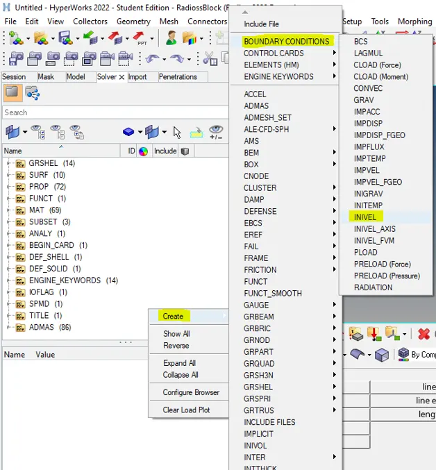
solver -> create -> boundary conditions -> Inivel
Now, we have to create a GRNOD id by select all components as entity id. And procedure to create GRNOD id is same as explained above. Also we will provide initial velocity of 15.65 mm/ms in translational x-direction and remaining two dimensions will remain constrained.
 \
\
Now, we have to create a GRNOD id by select all components as entity id. And procedure to create GRNOD id is same as explained above. Also we will provide initial velocity of 15.65 mm/ms in translational x-direction and remaining two dimensions will remain constrained.
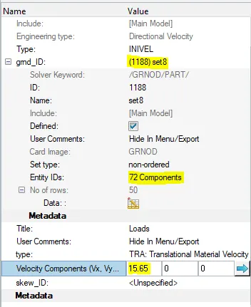
The velocity need to be applied is 35Mph,
since, the units are kg mm ms , thefore the value to input is 15.65mm/ms
Create appropriate interface ,friction 0.2 and recommended parameters.
- In order to create the interface of Type 7, we have to display solver browser by clicking View---->Browsers---->HyperMesh---->Solver.
- Once solver browser is displayed. Now we have to create appropriate interface i.e. Type 7 with recommended parameters as shown in picture below.
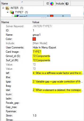
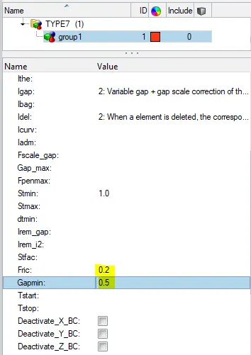
A type7 contact is created between all the 72 components with friction coefficient as 0.2.
Create rigid wall with friction 0.1.
- To create rigid wall with friction 0.1 between car and rigid wall.
- Solver---->Create---->RIGID WALL
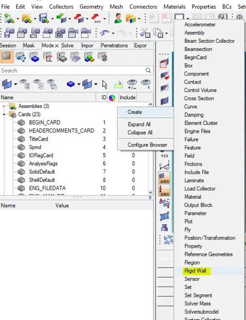
- To make a rigid wall, we need to create a reference node. First we will create a temporary node at the middle of bumper. After then we will translate that node to create a gap between car and rigid wall as shown in picture below
- In rigid wall, we have to create the recommended properties by selecting the temporary node in XM,YM,ZM then enter the search distance Dsearch of 1000 and friction value of 0.1. a sshown in below image.
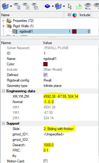
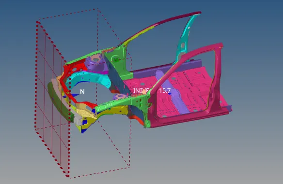
Time-step :0.5 to 0.1 microseconds and Run 80 ms.
- The run time is kept to be 80ms;
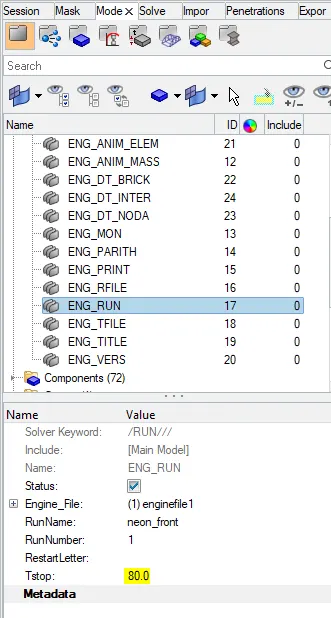
Time-step :0.5 to 0.1 microseconds.
- A type of time step option is “INTER” and time step control “DEL” is used.
- We have to keep 0.67 as time scale factor and 0.0005 as a minimum time step control.
- If time step gets reduced below the minimum time step, then this algorithm will add some mass to the element which leads to maintain time step more than minimum time step.
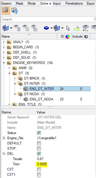
This method is used in order to control the time step.
- A type of time step option is “NODA” and time step control type “CST” is used.
- In order to create ENG_DT_NODA we have to follow steps as explained below.
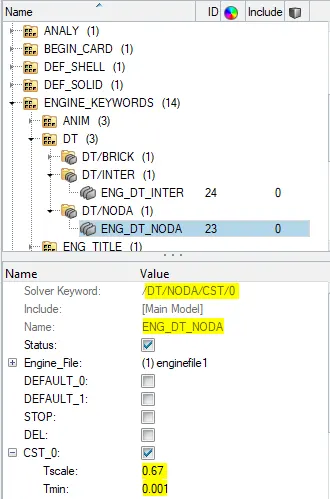
This method is used to control the time step from the nodes.
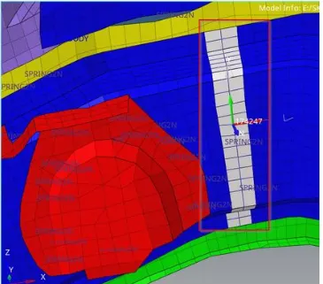
Sectional force in the rails at location of indicated node 174247.
- First we have to display the nodes i.e. 174247. In order to display the node, we have to follow:
- Tool---->numbers---->By id---->Type node number---->Display---->on.
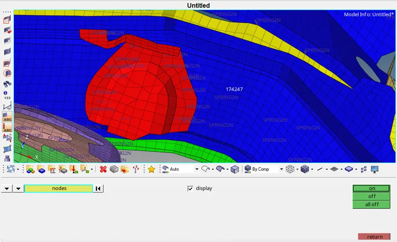
- In order to create SECTION first we have to create the FRAME CARD. In this moving frame is attached with the nodes which is selected as origin.4
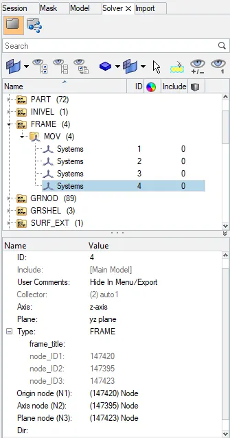
- In order to assign parameters in FRAME---->MOV, we have to follow. In this we have to define origin node and then define the z-axis with second node which is in the direction of crash. And then we have to define the third node for plane as shown in picture below.
- Now, we have to create FRAME card in solver browser. In order to create FRAME card, we have to follow.
- Once axis has created at node 174247, it will look like as shown in picture below.
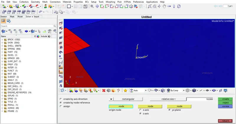
- Now we have to create the SECTIONAL force at RAIL_1. In order to create SECTIONAL force we have to follow:
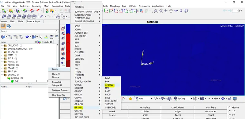
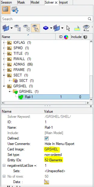
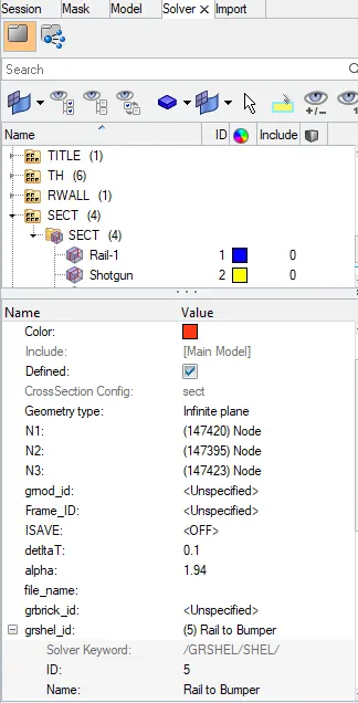
- Now we have to assign this GRSHELL id in the SECT parameters as shown in picture below.
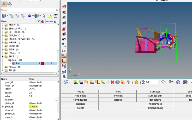
- Now we have to give output blocks request in model browser as shown in picture below.
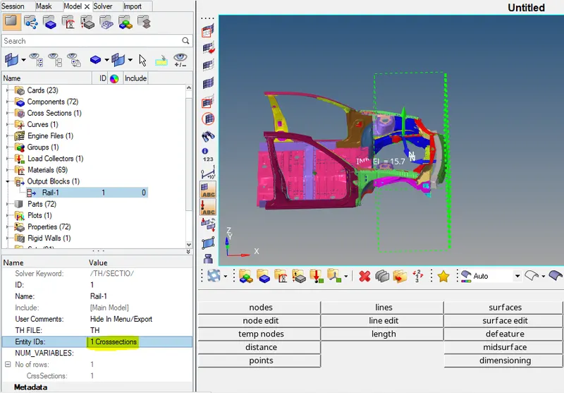
Axial force received on the rails from bumper.
- To add axial force received on the rail from bumper.
- First we have to create a MOV collector in FRAME card as shown in picture below.
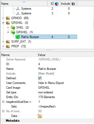
Now we have to make GRSHELL in order to create GRSHELL create >>GRSHELL>>Grshell
Now we have to assign parameters in SECT as shown in picture below.
- Now we have to give output blocks request as shown below.
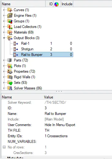
Shotgun cross sectional forces.
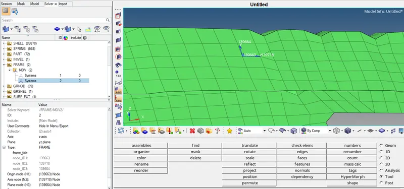
- To find cross sectional forces in shotgun.
- First we have to create a MOV collector in FRAME card as shown in picture below.
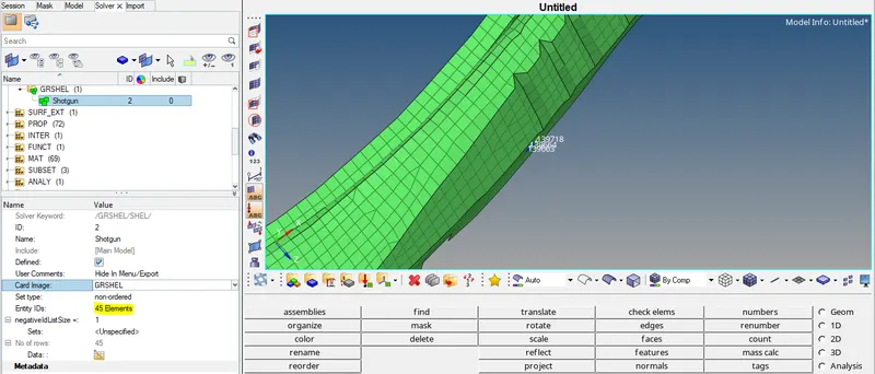
- Now we have to assign GRSHELL id by selecting element as shown in picture below.
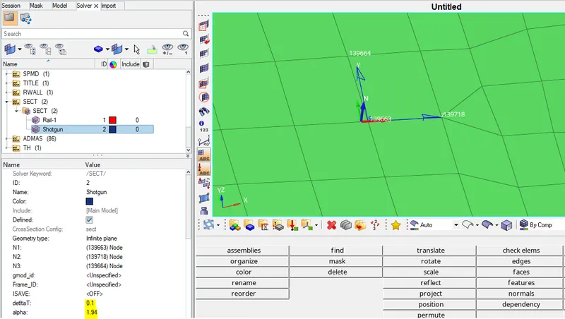
- Now we have to assign parameters in SECT as shown in picture below.
- Now we have to give output blocks request as shown below.
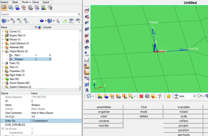
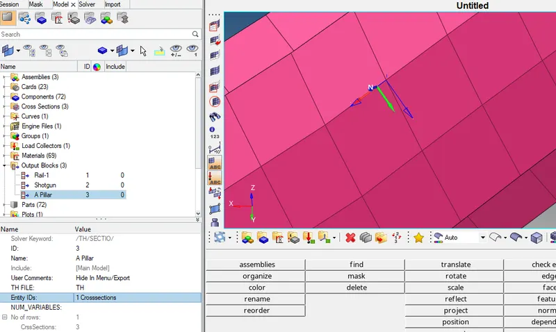
A pillar cross section.
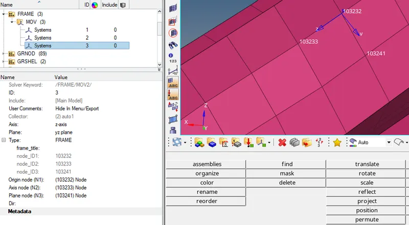
First we have to create a MOV collector in FRAME card as shown in picture below.
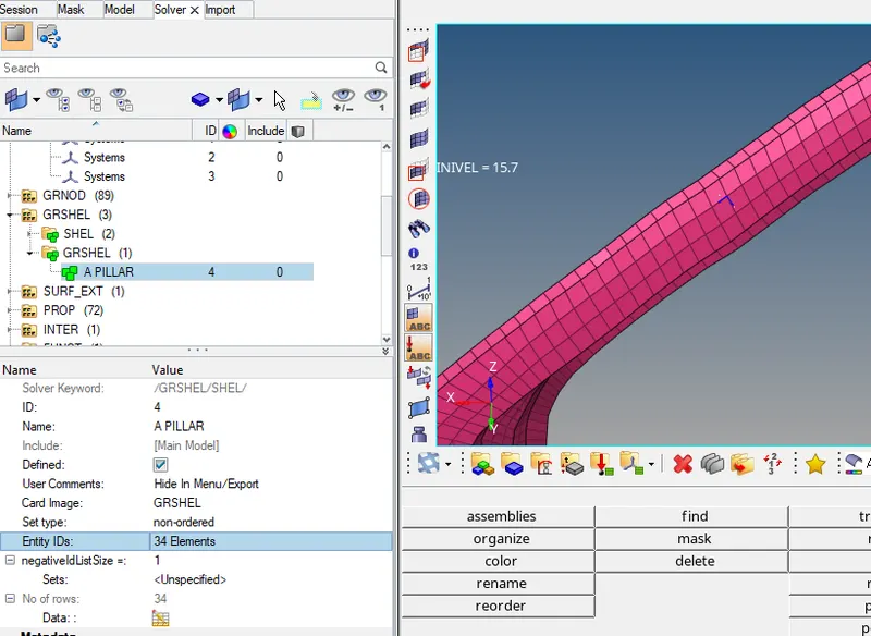
Now we have to assign GRSHELL id by selecting element as shown in picture below.
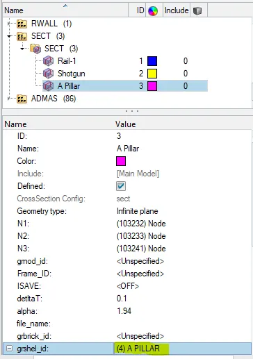
Now we have to assign parameters in SECT as shown in picture below.
Now we have to give output blocks request as shown below.
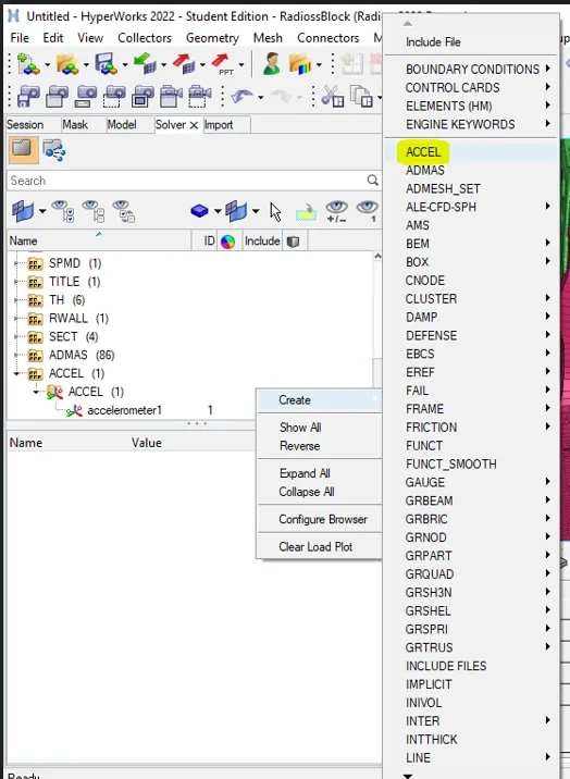
Acceleration curve received on the accelerometer at base of B pillar (on B pillar rocker).
- First we have to create ACCEL card in solver browser as shown below.
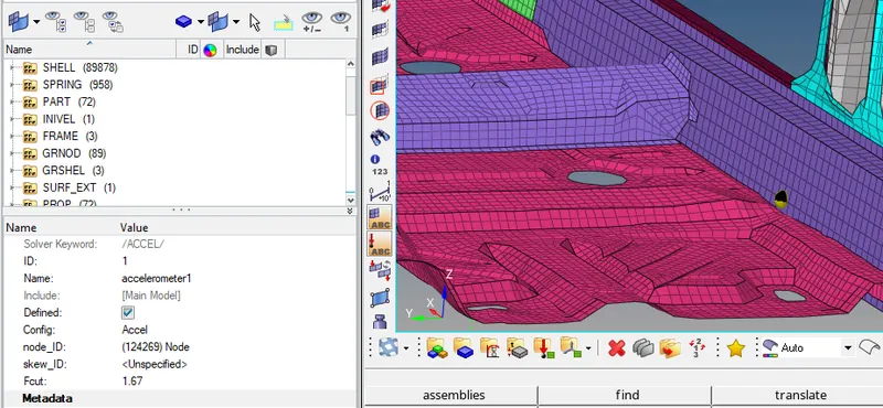
Now we have to assign accelerometer parameters as base of B pillar.
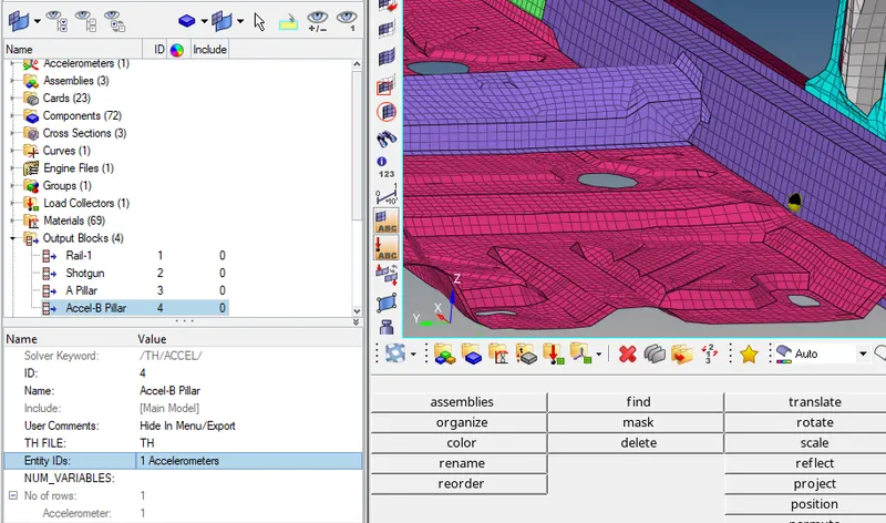
Now we have to give output Blocks request as shown in picture below.
Intrusions on the dash wall 66695,66244.
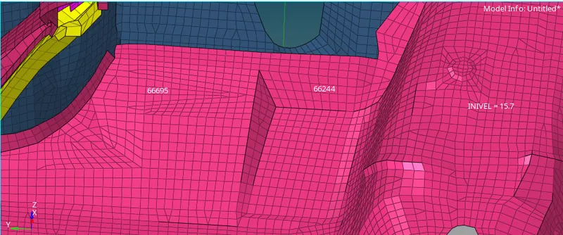
- To calculate intrusions on the dash wall at node 66695 and 66244.
- In order to show these nodes at number 66695 and 66244, we have to follow steps already explained in step 9. Once nodes are generated, it will look like as shown in picture below.
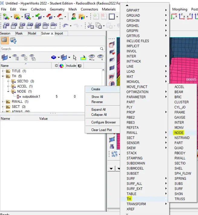
- Create a node time history, select the node and assign the newly created skew to that as shown in picture below.
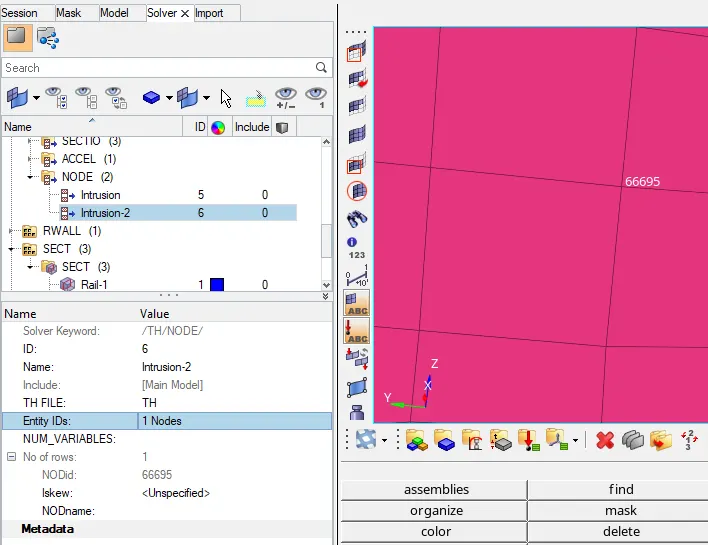
- Similarly, we will do same step for node 1 and 2. Then we have to assign output blocks request for both intrusion as shown in picture below.
RESULT AND OSERVATION
Simulation on the FRONTAL CRASH:
- Now we can check the animation by run the simulation with default properties by following:-Analysis---->Radioss
- Now we have to give location to export the input file:
- Options helps to choose number of cores to solve this problem, here we have chosen 4 number of cores by (-nt 4).
- Then click on Radioss, and new window will get pop-up. A simulation will start to show result,
- After run the simulation on model, solver has generated different files such as engine listing file, animation, time history and then restart file.
- Now, in order to check the energy error and mass error. We have to open the output file in notepad.
- Once output file is opened, we can see the results.
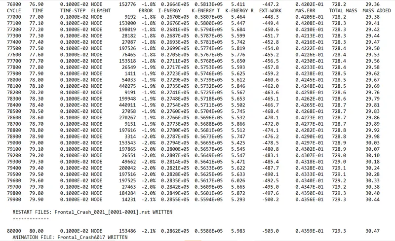
- Time step is calculated at every cycles. If model time step value is less than 0.001, then solver will take default time step value i.e. 0.001. Because we are using “CST” which means solver will use default time step value, if model time step value falls below nodal time step. To keep time step constant, it will add some mass on the node for which control the time step.
- In zeroth cycle model time step is less than nodal time step. Control method has to be used constant time step having value of 0.001 and mass has been added on the nodes. If mass percentage lies in between 1 to 3, that means results will be acceptable.
-
An error is positive which means some energy is generated in the body.
-
Now we have to switch from Hypermesh mode to Hyperview mode. Then we have to select the appropriated (.h3D) file. And then we have to click on Apply to view the results.
-
By using different animation controls, we can check and animate the results as shown in picture below.
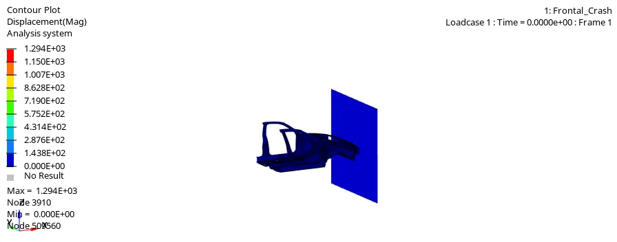
Contour plot for Displacement
- Maximum displacement reaches upto 1290 mm over the period of time
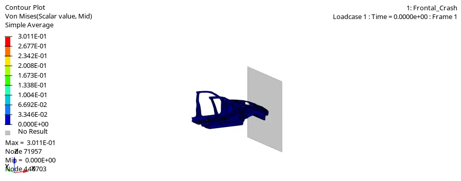
Contour plot for Von Mises
- Stresses are distributed in the entire model. More stress is generated on the front rail, shotgun, bumper and other front components. Generated stress is less because initial velocity applied is less.
- And balancing masses are added at the end of panel. If mass applied is higher, then inertial will also high. In this case model is obeying second law of motion because mass added is trying to move the car in the forward direction, when a car collided with wall.
HYPERVIEW
Now we have to switch from HyperView mode to HyperGraph 2D mode.
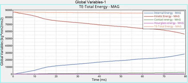
ENERGY PLOT:-
- As we can see, from below graph that kinetic energy is decreasing from starting time to termination time. Because a velocity is decreased over a period of time. Kinetic energy is directly proportional to velocity. Kinetic is started at 87000 and ended up with 55000.
- Internal energy is increased over a period of time. Because it has some work done in the car.
- And no hourglass energy is dissipated, since QEPH formulation has been used.
- As we know total energy is the combination of internal, kinetic energy which has been plotted below.
- Our Requirement from an Ideal Simulation is that we have minimal Contact energy and maximum Energy absorption/Deformation in the elements. We can check the Energy error in the Engine output file, which has maxed out at -2.1% which is within the limits for it to be. Our Mass error is also 0 % which means that the solver did not need to add mass onto the nodes to reduce the time step to further avoid the Hourglass Error.
- Once all parameters are filled, we have a required graph as shown in picture below.
Dash wall intrusion at 66695 and 66244 node:
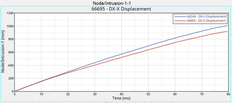
- From the above graph, we can see that the maximum intrusion that occurred in the spring (Node 66695) during a crash is 900 mm, and the maximum intrusion that occurred in the spring (Node 66244) during a crash is 1000 mm. Practically this elongation referred to which extent the foot pedal or the passenger's legs will move once the crash is happening. From the animation, we can notice that there is deformation that occurred at this location and the elongation is also low. Hence, we can conclude that there are injuries will happen to the Passenger/driver.
SECTIONAL FORCES:
ACCELEROMETER:
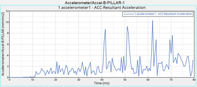
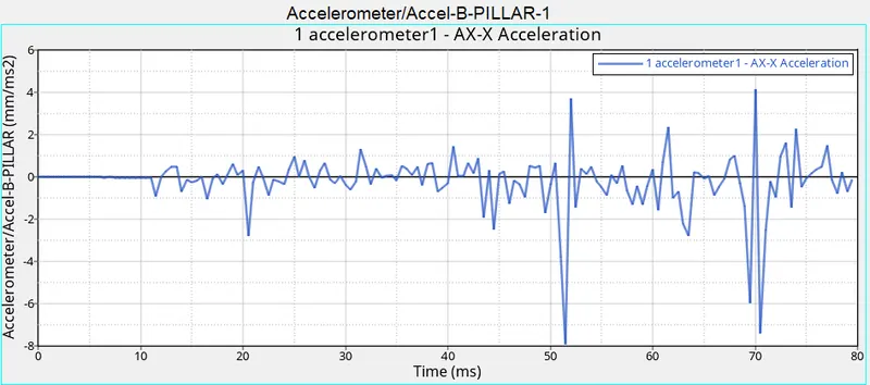
- As we all know that an Acceleration is the rate of change of velocity. To measure the acceleration, we have placed the accelerometer near the Rocker of B-Pillar as mention in question.
- Once the Car hits the rigid wall with the initial velocity, the acceleration of the vehicle during the crash is not constant across the structure. The front of the vehicle slows down immediately as it hits the rigid wall, while the rest of the structure decelerates at a slower rate as seen in the graph. As seen from the graph there is a sudden increase in the acceleration, this might be because of some vibration that occurs during the crash with respect to the point where the accelerometer is placed.
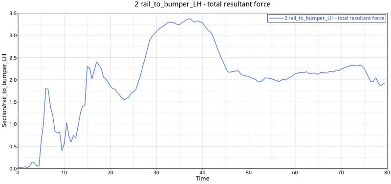
Rail to Bumper:
The force at Bumper is 3.3 kN. During the simulation, the Bumper will come into contact with the rigid ball first hence it will experience the maximum force. The Bumper will absorb some force and transmit the rest to the Rails and other connected components.
LEARNING OUTCOME:
- Learned how to set up a frontal crash test.
- Learned how the rigid wall interface works and can lead to incompatible Kinematic conditions.
- Learned how Sectional forces are generated.
- Learned how the distribution of forces among the components during a frontal crash.
- Learned how some components are designed to deform in such a way to ensure the safety of the passengers inside the cabin.
- Learned how to Debugging errors in order to get the right results.
CONCLUSION:
The given model was simulated for the frontal crash using Radioss and the results obtained were validated. The graphical results were plotted for all the test cases. From the simulation, it can be observed that there was minimum deformation in the cabin, and also minimum intrusion was found in the driver’s seat area.