Assignment 6- Frontal impact test on Neon car BIW component in RADIOSS
OBJECTIVE:- To perform a frontal crash test analysis on the BIW component and obtained required plots for the output requests.
Frontal crash-BIW
- Check unit system and either follow[Mg mm s] or [Kg mm ms].
- Create an appropriate interface, friction 0.2 and recommended parameters.
- Make sure of no penetrations and intersection.
- Correct rigid bodies if any issues.
- Create a rigid wall with friction 0.1.
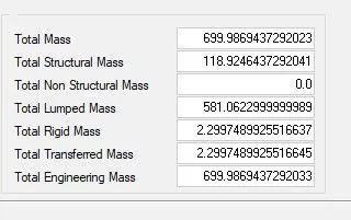
- Compare the model weight with the full-scale 300k nodes model and use added masses to reach target weight 700kg while getting CG about the required range.
- Initial velocity 35 mph.
- Use model checker to ensure good quality.
- Time-step: 5 to 1 ms
- Run 80 ms.
Output requests:
- Sectional force in the rails at the location of indicated node 174247.
- The axial force received on the rails from the bumper at node 147344
- Shotgun cross-sectional forces at node 139604
- A pillar cross-section at node 103242, 4929
- Acceleration curve received on the accelerometer at base of B pillar (on B pillar rocker).
- Intrusions on the dash wall 66695,66244.
PROCEDURE-
- Open HyperMesh and load the neon_front_0000.rad file via import.
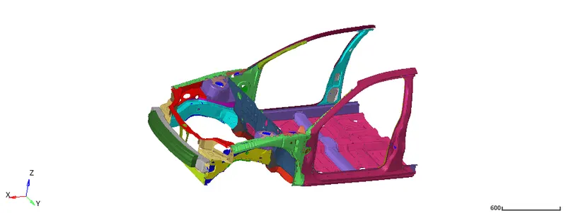
1-Check unit system and either follow[Mg mm s] or [Kg mm ms].
- The unit system is kg mm ms, obtained from the neon_front_0000.rad file opened from notepad

2- Create an appropriate interface, friction 0.2 and recommended parameters.
- To create an interface, first open solver tab then right-click -> create -> inter -> Type7, provide the recommended properties.
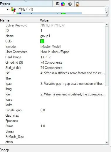
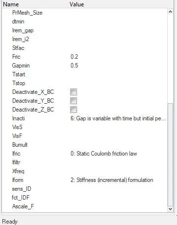
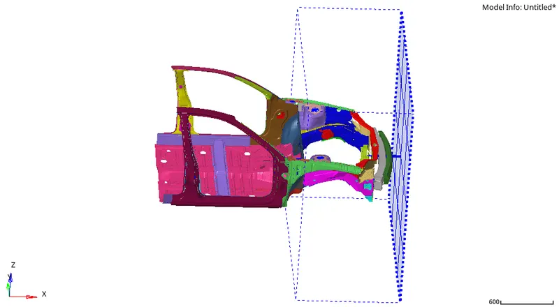
3- Create a rigid wall with friction 0.1.
- To create a rigid wall, in solver tab -> right-click to create -> RWALL -> Plane -> provide recommended values
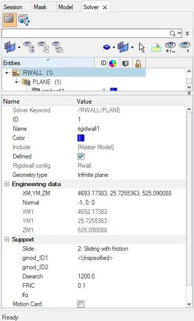
4- Make sure of no penetrations and intersection.
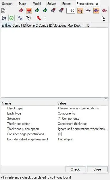
- To check penetration and intersection, in HyperMesh menubar goto Tools -> Penetration Check -> Enity Type= Component -> Selection= Select all the component -> Check
- There should be zero collision and intersection.
5- Run 80 ms and Time-step: 5 to 1 milliseconds.
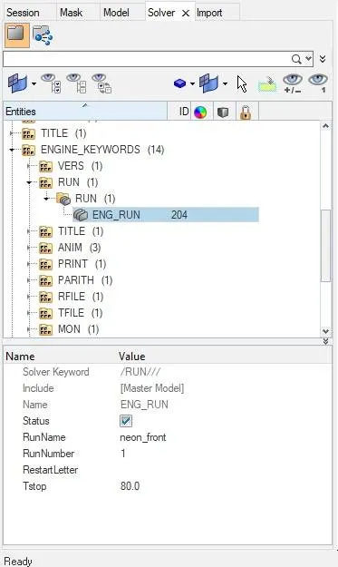
- For Run time in solver tab, goto to ENGINE_KEYWORDS -> RUN -> ENG_RUN -> Tstop= 80 ms
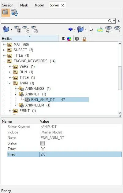
- For Time-step in solver tab, goto to ENGINE_KEYWORDS -> ANIM -> ANIM/DT -> ENG_ANIM_DT -> Tfreq= 2.0 ms
- That mean the number of frames generated will be 80/2= 40 frames.
6- Initial velocity 35 mph.
- Convert the 35 mph to mm/s -> Divide the speed value 35mph by 2.237 = 15.645954 mm/millisecond
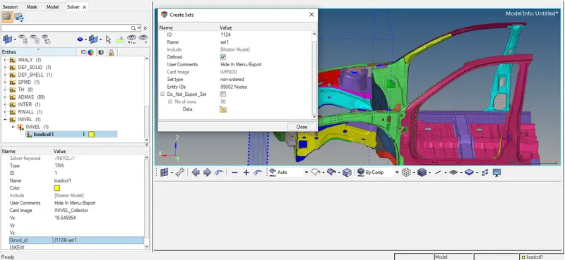
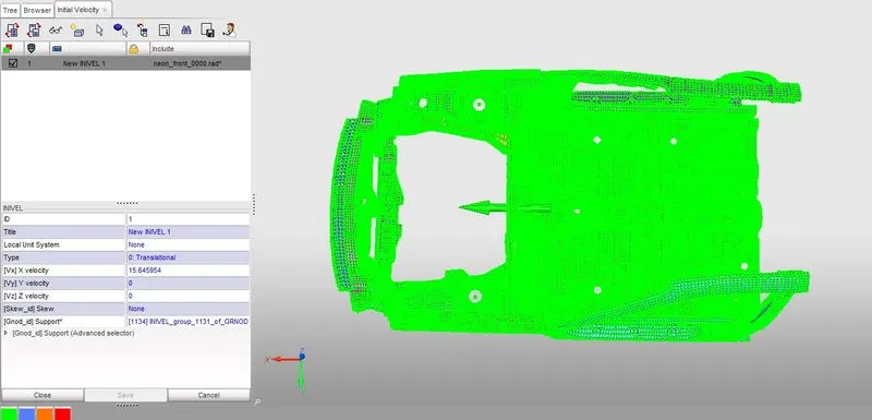
- To apply the initial velocity, in the solver tab -> right click to create -> BOUNDARY CONDITIONS -> INVEL -> Vx= 15.645954 -> Grnod_id= right-click to create, in Create set choose entity id to nodes and select all the displayed nodes on the screen and click on Proceed.
7- Compare the model weight with the full-scale 300k nodes model and use added masses to reach target weight 700kg while getting CG about the required range.
- Open a HyperCrash window, set the unit to N, mm, s, T, and open the NEON_OP3D00.rad file via import.
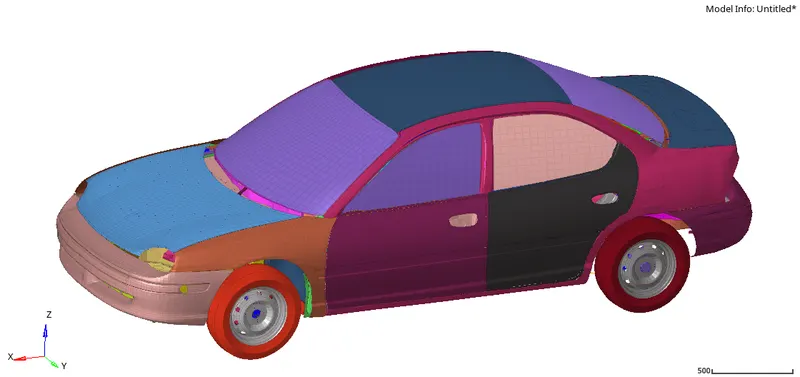
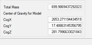
- In the menubar goto Mass -> balancing, the total mass of the car can be seen which is 1.216555330E+00 tonne, and the CoG is located at X= 3.124104786E+03, Y= 5.774607253E+00 and Z= 5.311952651E+02.
- Now in HyperCrash, load the neon_front_0000.rad file, and in the menubar goto mass -> balancing, it will show the model mass and CoG of the model. To balance mass, under menubar goto LoadCase -> added mass -> Create a new -> Type 1 -> give MASS and grnod_id, while adding mass also check in the mass balancing tab for the total mass and the CoG. Once the target of 700 kg is achieved with the desired CoG point in hypermesh choose the same node and same mass value to attain the target mass and CoG in the required range.
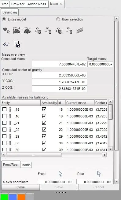
- To add mass in HyperMesh, in solver tab right-click to create -> ADMAS -> Mass type= 1 -> Provide the mass value -> grnd_ID= right-click to create, in the Create Sets choose the Entity IDs which is as nodes, select the required the nodes in the graphics -> Proceed. Similarly, add all the mass of values and position similar to the one created in HyperCrash.
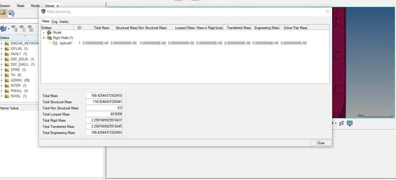
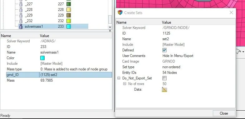
- After adding the mass the position of the CoG in HyperMesh can be compared with the position in HyperCrash, the position should be near to the value and it can be checked by in the menubar under Tools -> Mass Details -> Mass, CoG and Inertia.
8- Create the Sectional Force at the Front rail, shotgun, A-pillar and A-pillar bottom in the left and right-hand side of the BIW model and assign the output request.
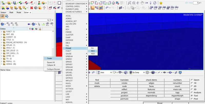
- Before creating the section, first of all, Frame must be generated for that by in the solver tab right-click to create -> Frame -> Mov -> Create node by reference -> Provide the node for Origin, Axis and plane -> Create. Similarly, create a frame for all the point where cross-sectional force is required.
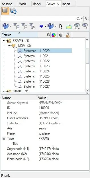
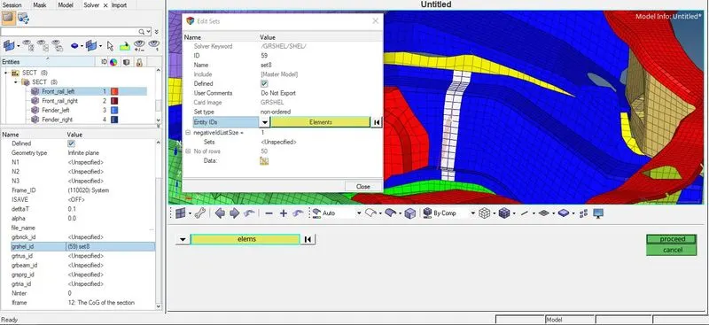
- After creating the Frame, create the sectional force by in solver tab right-click to create -> sect -> sect -> Frame_ID= choose the frame created -> deltaT= 0.1 -> alpha= 1.67 -> Iframe= 12 -> grshel_id= right-click to create, in the create sets choose entity elements along the strip -> proceed. Repeat this step for all the crossectional part.
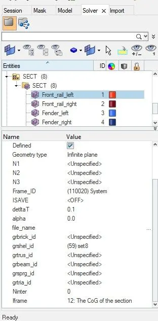
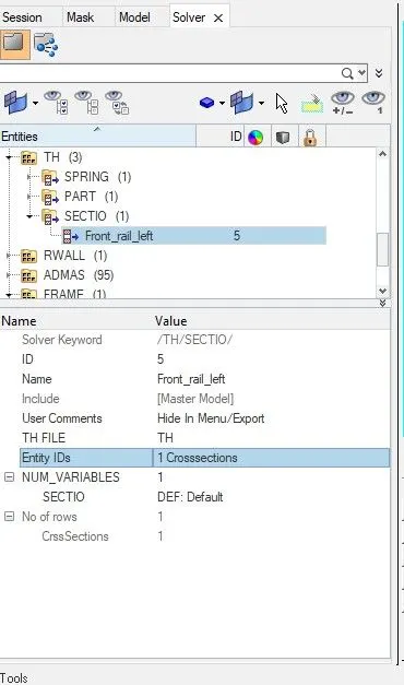
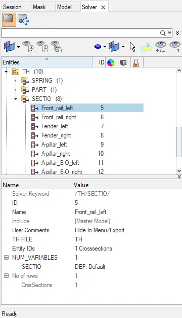
- After creating the section, the output request of the frame can be called by in the solver tab right-click to create -> TH -> SECTIO -> Entity IDs= select the respective crosssection from the created in the crosssection -> NUM_VARIABLES= 1. Similarly, create the output request of all the created crosssection above.
9- The axial force received on the rails from the bumper.
- For the axial force on the rail from the bumper, a TYPE 7 contact interface has been created with the rail being the slave and bumper as the master and it is done by in the solver tab right-click to create -> INTER -> TYPE 7 -> Grnod_id= the left Headlight bracket component is chosen as a slave, Surf_id= the bumper component is chosen as a master -> rest criteria as usual. Similarly, for the right Headlight bracket as a slave and bumper as a master component is selected for the right axial force.
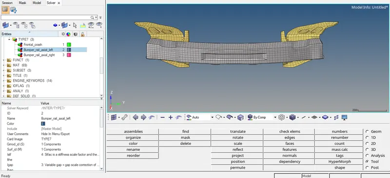
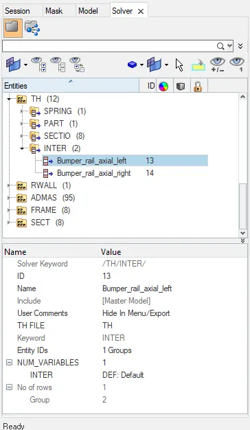
- For the Axial force also output request can be called by in the solver tab right-click to create -> TH -> INTER -> Entity IDs= select the Type 7 created for the axial force for -> NUM_VARIABLES= 1. Request created for bot left and right.
10- Acceleration curve received on the accelerometer at base of B pillar (on B pillar rocker).
- To create accelerometer, in the solver tab right-click to create -> ACCEL -> node_ID= select a node on the B pillar rocker. Similarly, create accelerometer for the right side also.
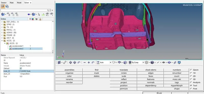
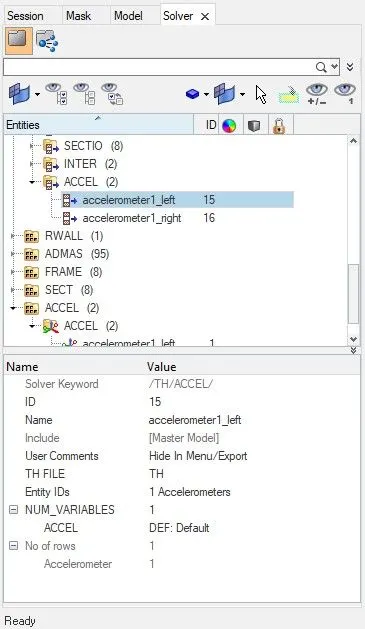
- The output request for the accelerometer can be called by in the solver tab right-click to create -> TH -> ACCEL -> Entity IDs= select the accelerometer created -> NUM_VARIABLE= 1.
11- Intrusions on the dash wall 66695,66244.
- To create intrusion, first, create a skew by in the solver tab right-click to create -> SKEW -> MOV -> choose the origin axis and plane.
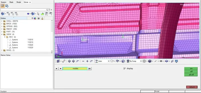
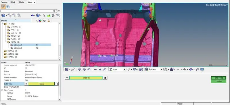
- After creating skew the intrusion can be called by in the solver tab right-click to create -> TH -> NODE -> Entity IDs= Provide the node ID ->Iskew= choose the skew created above.
12- Model Check
- After completion of all the task save the component via Export as RADIOSS file and open that saved file in HyperCrash and run a model check by under menubar goto Quality -> Model Checker -> Run. All the error and warning will be visible under the checks, the warnings can be ignored but have to resolve all the error.
- The error can be solved by first locating the element and then updating the node of the rigid element by 1D -> Rigid -> Update -> connectivity.
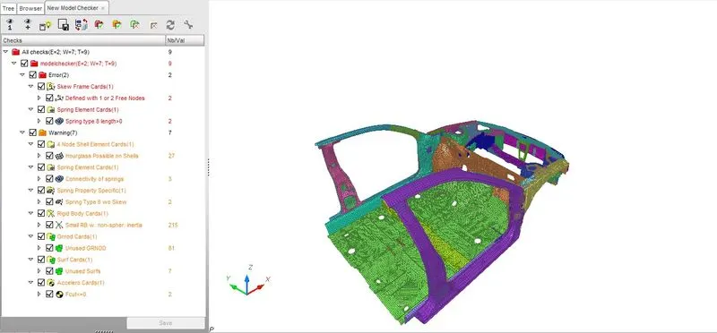
- In the HyperMesh resolve all the error and again verify with the HyperCrash.
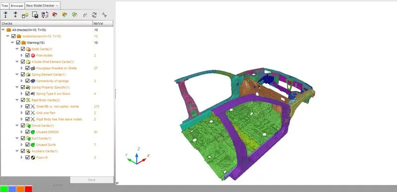
- After resolving all the error and before going into simulation check the ENGINE_KEYWORDS and Time history for all the required files are correctly mentioned.
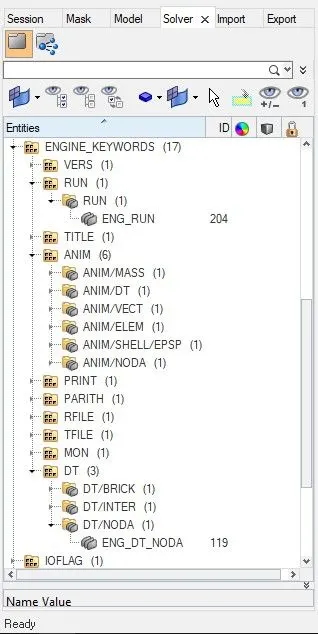
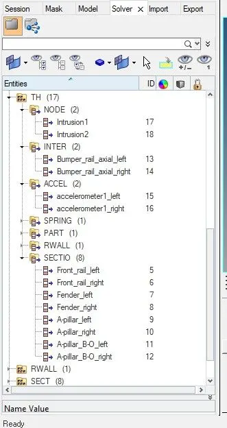
- Save the file via Export as a RADIOSS file, then in a new session open the saved neon_front_0000.rad via import in HyperMesh.
- For analysis goto Analysis -> RADIOSS -> choose the path to save -> option= -nt 4 -> RADIOSS

- After completion of the analysis open the file location and open the obtained engine file neon_front_0001.out via notepad.
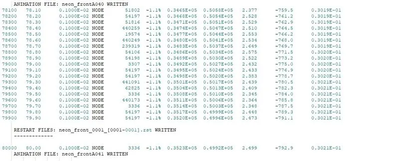
| CASE | Number Of Cycles | Energy Error (%) | Mass Error (%) | Simulation Time (sec) |
| neon_front_0001 | 80000 | -1.1 | 0.3021E-01 | 3689.04 |
Output Files:-
1) Von Mises
- After running Radioss, open hyperview and load the h3d file obtained, the Von-Mises contour plot can be obtained by select "Contour" -> Result type = Von Mises(s) -> Averaging method = simple -> Apply.
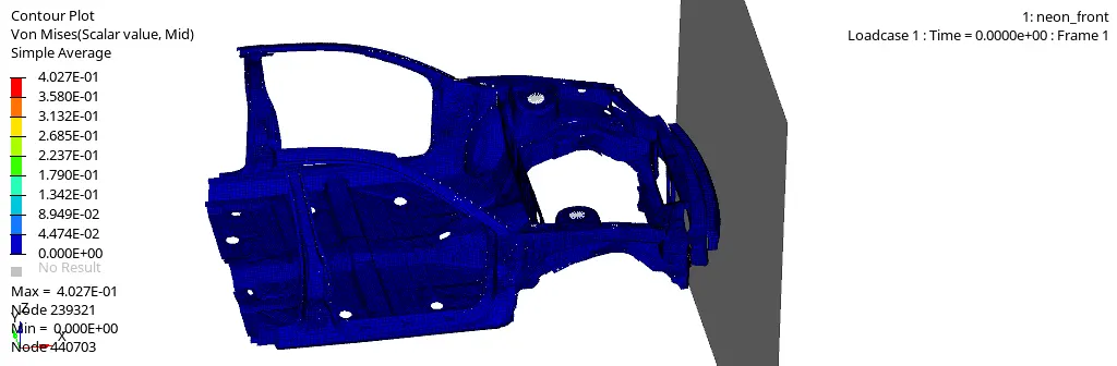
- The maximum Von Mises stress is obtained is of 0.4027 GPa.
2) Global Energy
- To obtain the required graphs split the GUI and from "client selector" select HyperGraph 2D and in the data file load the T01 file obtained from simulation also for X type= time, Y type = Global variables, Y request = Internal energy, Kinetic energy, Hourglass energy, Total energy, y component = MAG and click on apply.
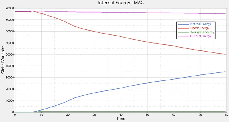
- As the Kinetic energy decreases the Internal energy increases and it can be observed that after 80 ms duration also both have not reached their peak values. Total energy remains constant while there is a slight increase in Hourglass energy.
3) Rigid wall
- For the rigid wall forces graphs, X type= time, Y type = Rigid wall/TH_RW, Y request = 1 rigidwall, Y component= NF, TF and total resultant force and click on apply.
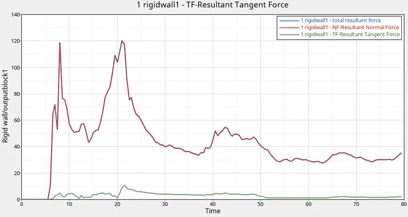
- The "total resultant force" reaches the first peak when the bumper interacts with the wall and the second peak when the fender starts to deform.
4) Contact Energy
- For contact energy graph, X type= time, Y type = Global variables, Y request = Contact energy, y component = MAG and click on apply.
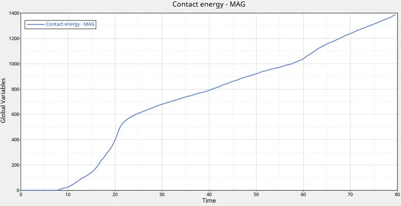
- For the first 10 to 20 ms the contact energy increase suddenly when the bumper hits the wall and then it starts increasing as the body component interacts.
5) Sectional force in the front rail at the location of indicated node 174247
- For the sectional energy graph, X type= Time, Y type= Section/ Front_rail_left and right, Y request= 1 Front_rail_left and 2 Front_rail_right, Y component= total resultant force
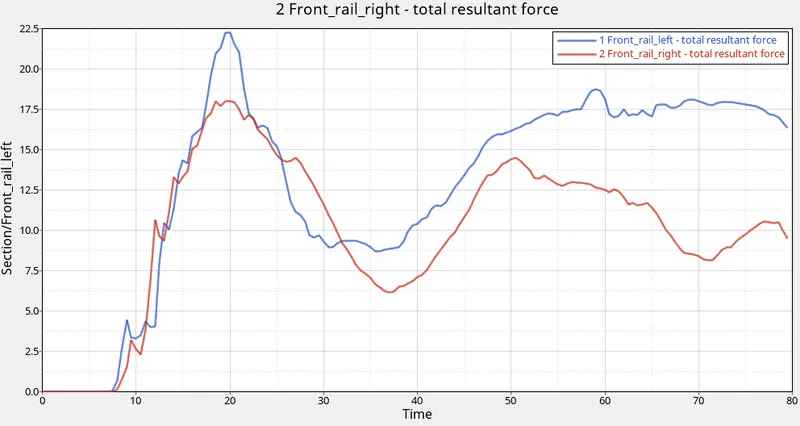
- The peak force observed in the left rail is 22.23 kN and in the right rail is 18.01 kN. The left rail experienced a little large amount of force compared to the right rail.
6) Sectional force at the fender.
- For the sectional energy graph, X type= Time, Y type= Section/ Fender_left and right, Y request= 3 Fender_left and 4 Fender_right, Y component= total resultant force
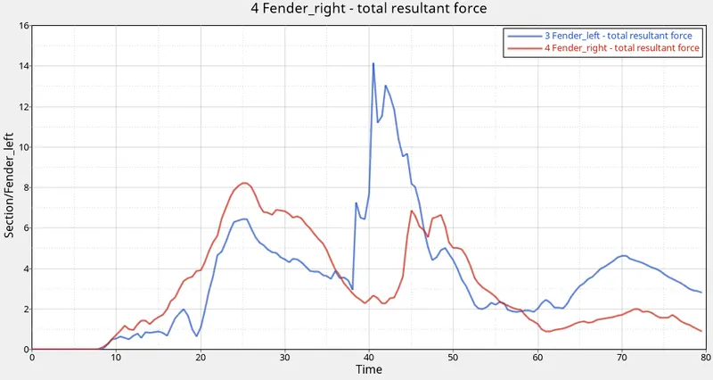
- The peak force observed in the left fender is 14.14 kN and in the right fender is 8.20 kN.
7) Sectional force at the A-pillar
- For the sectional energy graph, X type= Time, Y type= Section/ A-pillar_left and right, Y request= 5 Front_rail_left and 6 Front_rail_right, Y component= total resultant force
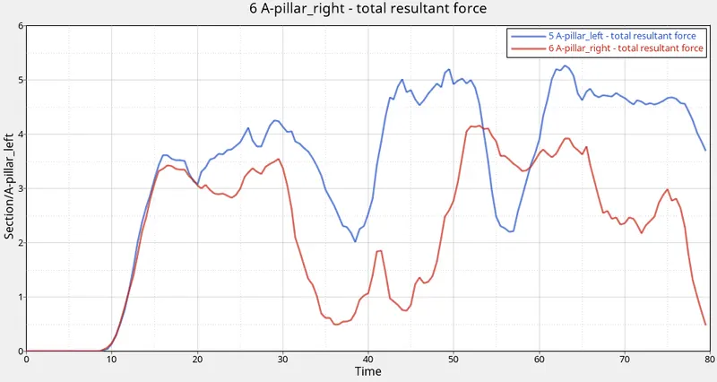
- The peak force observed in the left A-pillar is 5.26 kN and right A-pillar is 4.15 kN
8) Sectional force at the A-pillar_B-O
- For the sectional energy graph, X type= Time, Y type= Section/ A-pillar_B-O_left and right, Y request= 7 A-pillar_B-O_left and 8 A-pillar_B-O_right, Y component= total resultant force
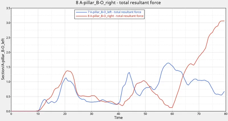
- The peak force observed in the left A-pillar_B-O is 1.63 kN and in the right A-pillar_B-O 3.06 kN.
9) Axial force at the bumper-rail.
- For the axial force graph, X type= Time, Y type= Interface/ Bumper_rail_axial_left and right, Y request= 2 Bumper_rail_axial_left and 3 Bumper_rail_axial_right, Y component= total resultant force
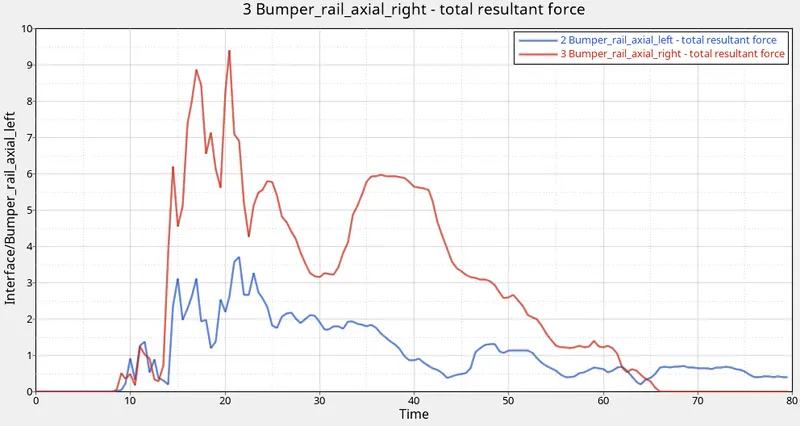
- The peak axial force is observed in the left Bumper-rail interface is 3.70 kN and in the right Bumper-rail interface is 9.40 kN.
10) Acceleration at B pillar
- For the axial force graph, X type= Time, Y type= Accelerometer/accelerometer1_left and right, Y request= 1 accelerometer1_left and 2 accelerometer2_right, Y component= ACC-Resultant Acceleration
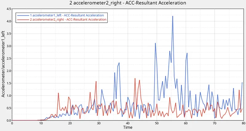
- The peak acceleration in the left accelerometer is 4.21 `(mm)/ (m s^2)` and in the right accelerometer is 1.69 `(mm) / (ms^2)`
11) Intrusions on the dash wall at node 66695 and 66244
- For the axial force graph, X type= Time, Y type= Node/Intrusion1 and 2 and right, Y request= 6695 and 66244, Y component= DISP-Resultant Displacement
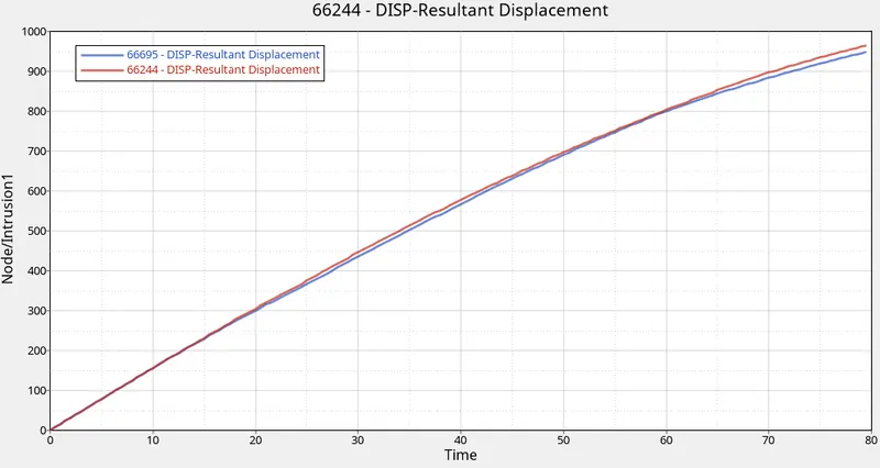
- The peak intrusion in the node 6695 is 948.59 mm and in the node 66244 is 964.29mm.
Result:-
- Among all the sectional forces the front rail experienced a huge amount of force comparison to others.
- Among all the sectional forces the A-pillar_B-O experienced the least amount of force comparison to others.
- The axial force on the right side of the Bumper-rail interface experience a large amount of force in comparison to the left side of the Bumper-rail interface.
- The left side accelerometer of the B-pillar experience more acceleration than the right side accelerometer of the B-pillar.
- The intrusion on node 66244 is greater than the intrusion on node 6695
Conclusion:-
So by completing the frontal crash analysis of the BIW of the Neon model, I learnt how to set up the frontal crash analysis by setting up the contact interface, rigid wall, mass balancing, request output at the required position and acceleration setup.