Assignment 5- To study different type of contact interface type 7 and 11 and compare the results in RADIOSS
Objective:- To study different types of contact for the below-mentioned cases using HyperCrash and compare the obtained results and also mesh the bumper.
CASE 1: Run the crash tube model as it is.
CASE 2: Change the Inacti=6 and run.
CASE 3: Create the type 11 contact and run.
CASE 4: Remove both notches and remove boundary condition on rigid body node then run.
CASE 5: Create a new notch in the middle, select the whole section and run.
CASE 6: Create a new notch with nodes only from opposing 2 faces and run.
Compare the result for RWALL forces, contact forces, internal energy and TH/part.
(I) Crash Tube Analysis
CASE 1: Run the crash tube model as it is.
- Open Hypermesh, import the Crush_tube_0000.rad file as RADIOSS.
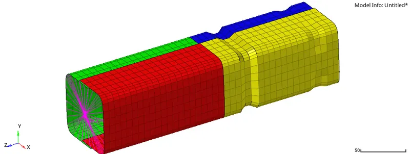
- In the menubar go to View -> browser -> Hypermesh -> solver -> right click to create -> TH -> Part -> Entity Ids= select all component. Save the file by export as RADIOSS.
- Again import the newly modified file and go to Analysis -> Radioss -> Input = choose where the file will be stored -> Option = -nt 4 -> Radioss.
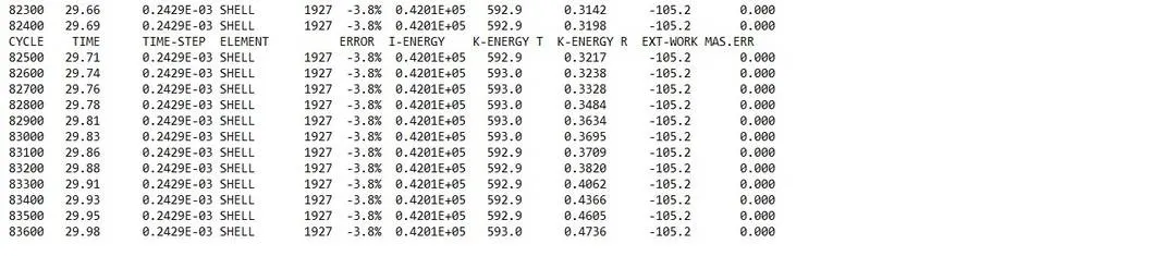
- After the analysis, open the engine file obtained Crush_tube_0001.out via notepad.
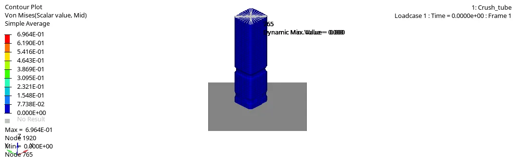
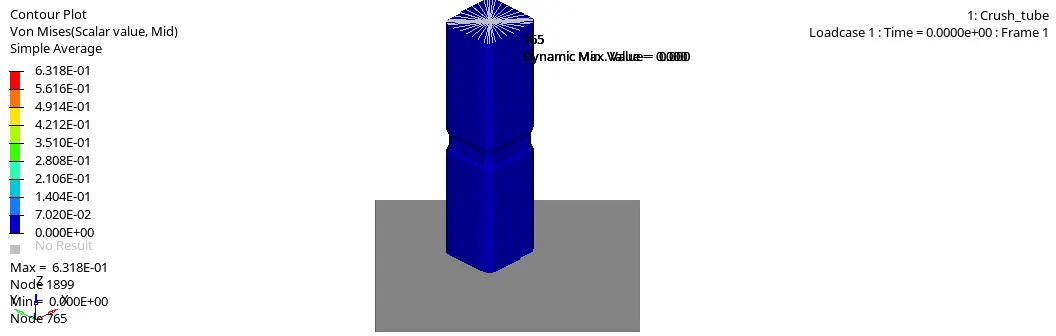
- After running Radioss, open hyperview and load the h3d file obtained, the Von-Mises contour plot can be obtained by, select "Contour" -> Result type = Von Mises(s) -> Averaging method = simple -> Apply.
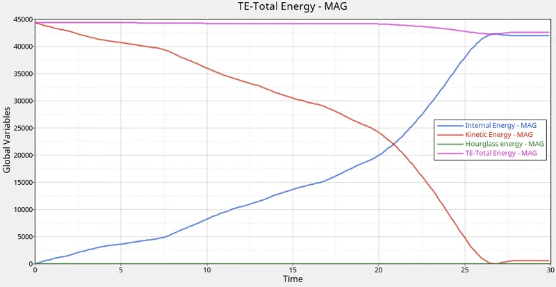
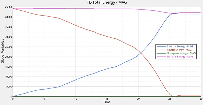
- To obtain the required graphs split the GUI and from "client selector" select HyperGraph 2D and in the data file load the T01 file obtained from simulation also for X type= time, Y type = Global variables, Y request = Internal energy, Kinetic energy, Hourglass energy, Total energy, y component = MAG and click on apply.
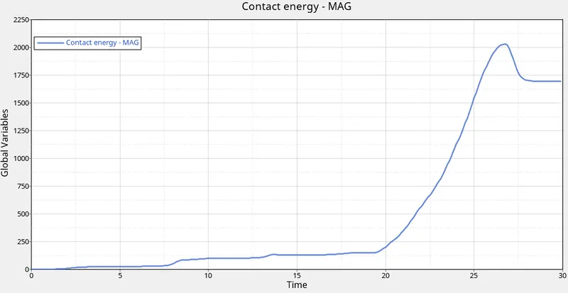
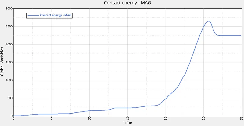
- For contact energy graph, X type= time, Y type = Global variables, Y request = Contact energy, y component = MAG and click on apply.
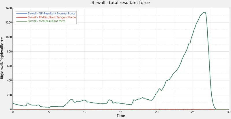
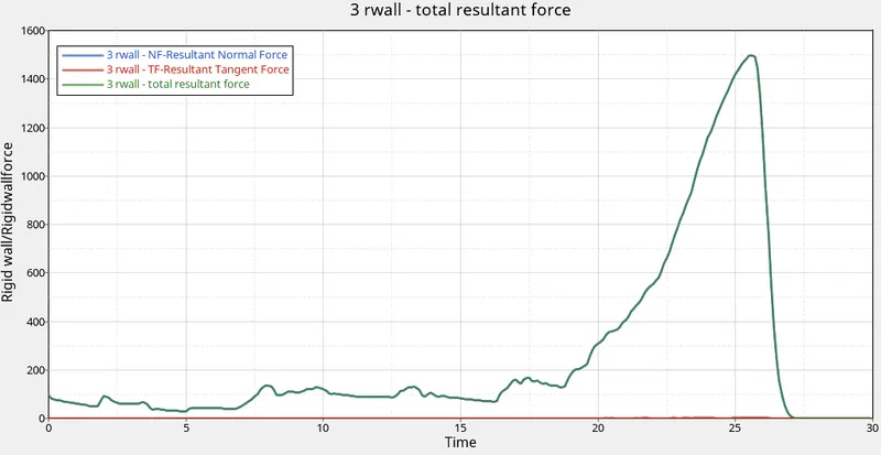
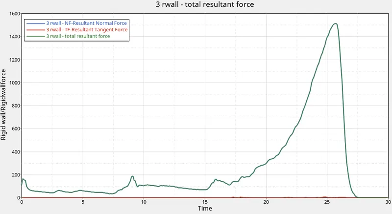
- For the rigid wall forces graphs, X type= time, Y type = Rigid wall/Rigidwallforce, Y request = 3 rwall, y component = NF- Resultant Normal Force, TF- Resultant Tangent Force and total resultant force, plot the 3 graphs individually.
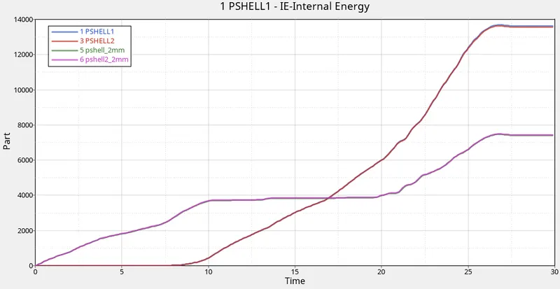
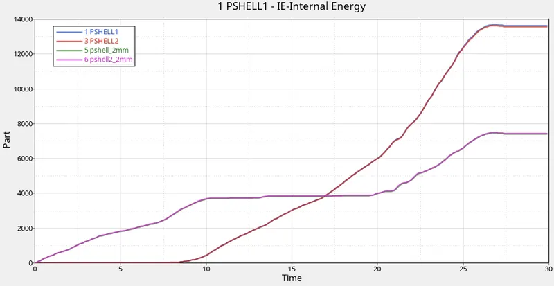
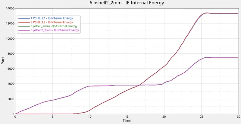
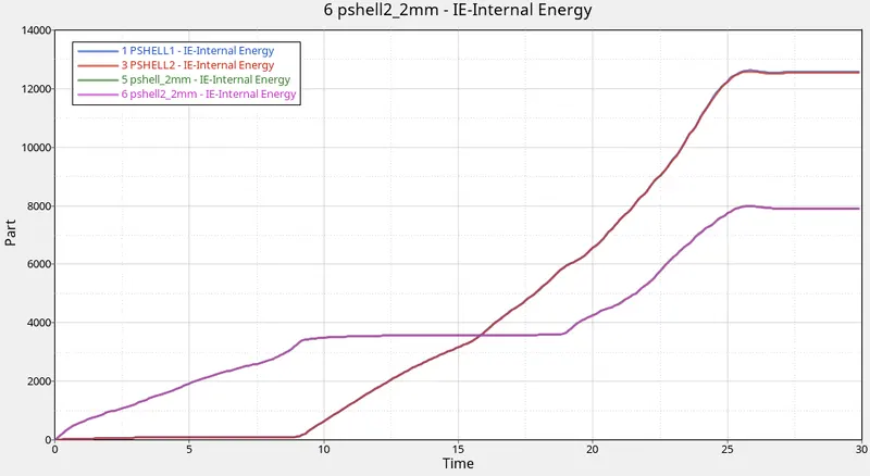
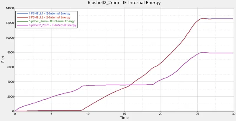
- For the part, X type= time, Y type = Part, Y request = PSHELL1, PSHELL2, pshell_2mm, pshell2_2mm , Y component= Internal energy and click on apply.
CASE 2: Change the Inacti=6 and run.
- Open Hypermesh under menubar goto Application open Hypercrash, import the downloaded Crush_tube_0000.rad file as RADIOSS.
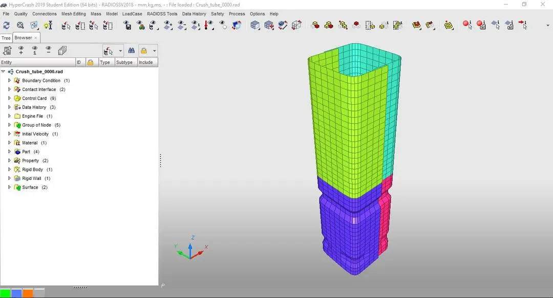
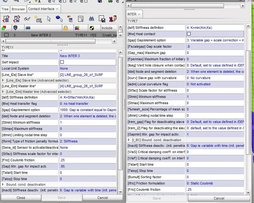
- In the menubar under "LoadCase" open "Contact Interface", change the Inacti = 6 for Type 7 and export the file as RADIOSS to save the changes made to the file (or the change for Inacti= 6 can also be done in hypermesh itself by model -> Groups -> self contact)
- In hypermesh open the modified Crush_tube_0000.rad file via import.
- In the menubar go to View -> browser -> Hypermesh -> solver -> right click to create -> TH -> Part -> Entity Ids= select all component. Save the file by export as RADIOSS.
- Again import the newly modified file and go to Analysis -> Radioss -> Input = choose where the file will be stored -> Option = -nt 4 -> Radioss.
- After the analysis, open the engine file obtained Crush_tube_0001.out via notepad.
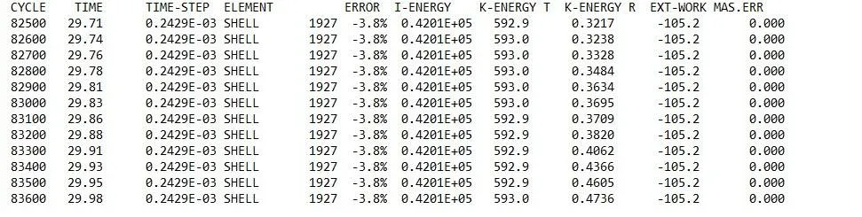
- After running Radioss, open hyperview and load the h3d file obtained, the Von-Mises contour plot can be obtained by, select "Contour" -> Result type = Von Mises(s) -> Averaging method = simple -> Apply.
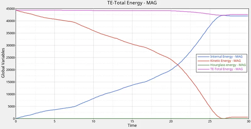
- To obtain the required graphs split the GUI and from "client selector" select HyperGraph 2D and in the data file load the T01 file obtained from simulation also for X type= time, Y type = Global variables, Y request = Internal energy, Kinetic energy, Hourglass energy, Total energy, y component = MAG and click on apply.
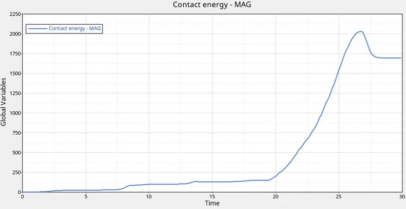
- For contact energy graph, X type= time, Y type = Global variables, Y request = Contact energy, y component = MAG and click on apply.
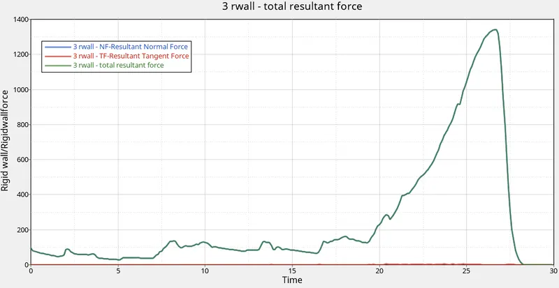
- For the rigid wall forces graphs, X type= time, Y type = Rigid wall/Rigidwallforce, Y request = 3 rwall, y component = NF- Resultant Normal Force, TF- Resultant Tangent Force and total resultant force, plot the 3 graphs individually.
- For the part, X type= time, Y type = Part, Y request = PSHELL1, PSHELL2, pshell_2mm, pshell2_2mm , Y component= Internal energy and click on apply.
CASE 3: Create the type 11 contact and run.
- Open Hypermesh and select HyperCrash under Application menubar.
- Import the downloaded Crush_tube_0000.rad file into the HyperCrash.
- For cross-reference first, select "Show Part Info" click on the component and choose the Interface here "Self Contact" and edit.
- From the LoadCase open Contact Interface -> Create new object -> Edge to Edge (Type 11) -> set the recommended values. After changing save the file via Export.
- In hypermesh open the modified Crush_tube_0000.rad file via import.
- In the menubar go to View -> browser -> Hypermesh -> solver -> right click to create -> TH -> Part -> Entity Ids= select all component. Save the file by export as RADIOSS.
- Again import the newly modified file and go to Analysis -> Radioss -> Input = choose where the file will be stored -> Option = -nt 4 -> Radioss.
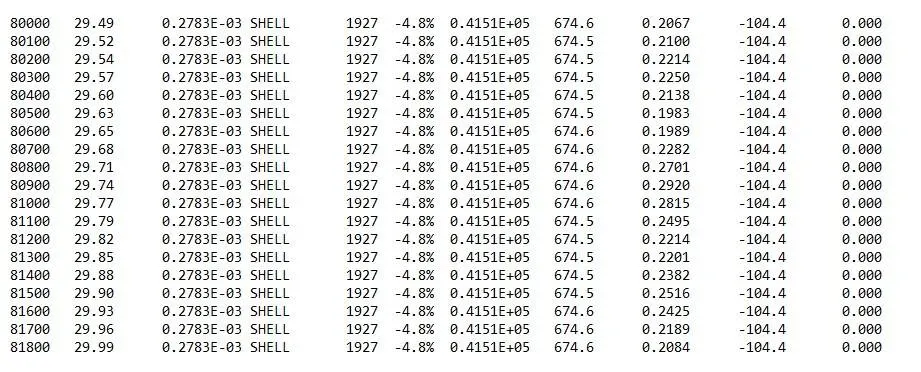
- After the analysis, open the engine file obtained Crush_tube_0001.out via notepad.
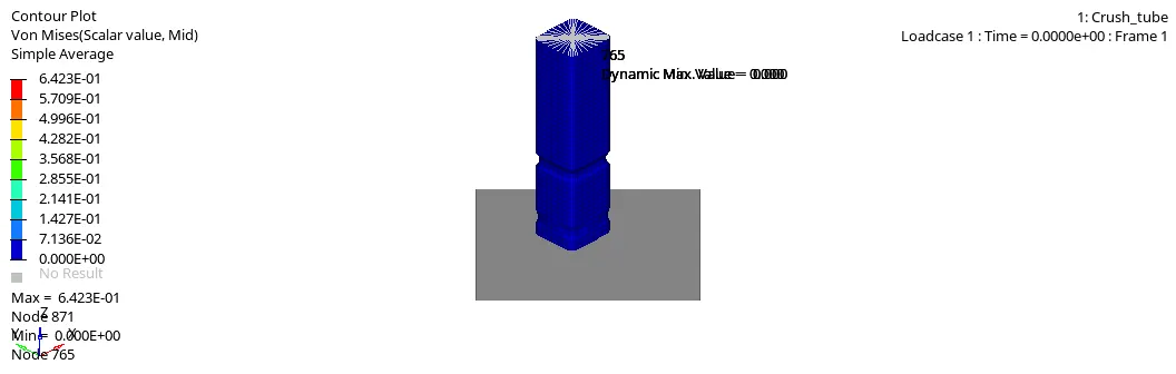
- After running Radioss, open hyperview and load the h3d file obtained, the Von-Mises contour plot can be obtained by, select "Contour" -> Result type = Von Mises(s) -> Averaging method = simple -> Apply.
- To obtain the required graphs split the GUI and from "client selector" select HyperGraph 2D and in the data file load the T01 file obtained from simulation also for X type= time, Y type = Global variables, Y request = Internal energy, Kinetic energy, Hourglass energy, Total energy, y component = MAG and click on apply.
- For contact energy graph, X type= time, Y type = Global variables, Y request = Contact energy, y component = MAG and click on apply.
- For the rigid wall forces graphs, X type= time, Y type = Rigid wall/Rigidwallforce, Y request = 3 rwall, y component = NF- Resultant Normal Force, TF- Resultant Tangent Force and total resultant force, plot the 3 graphs individually.
- For the part, X type= time, Y type = Part, Y request = PSHELL1, PSHELL2, pshell_2mm, pshell2_2mm , Y component= Internal energy and click on apply.
CASE 4: Remove both notches and remove boundary condition on rigid body node then run.
- Open Hypermesh and select HyperCrash under Application menubar.
- Import the downloaded Crush_tube_0000.rad file into the HyperCrash.
- To remove both notches in the menubar goto to "Mesh Editing" and select Move -> Align between nodes -> Begin point= select Pick a node and choose a node near the element, End point = Pick a node and choose a node near the element -> click on the middle node lying between begin and end point to align.
- Set the Type 11 interface as done above case. After aligning save the file via export as RADIOSS.
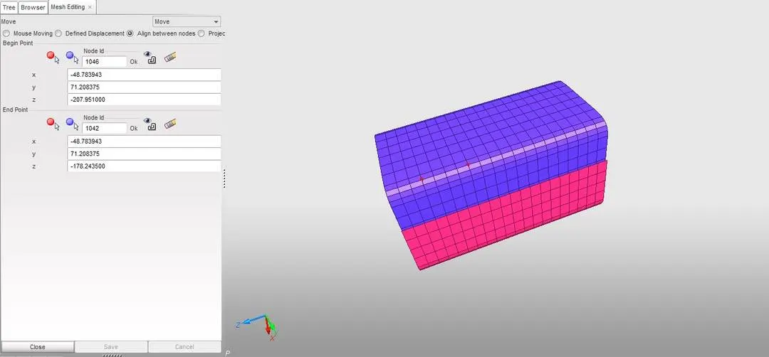
- In hypermesh open the modified Crush_tube_0000.rad file via import and under menubar go to View -> browser -> Hypermesh -> solver -> right click to create -> TH -> Part -> Entity Ids= select all component. After that delete the boundary condition by right click BC's -> delete. Save the file by export as RADIOSS.
- Again import the newly modified file and go to Analysis -> Radioss -> Input = choose where the file will be stored -> Option = -nt 4 -> Radioss.
- After the analysis, open the engine file obtained Crush_tube_0001.out via notepad.
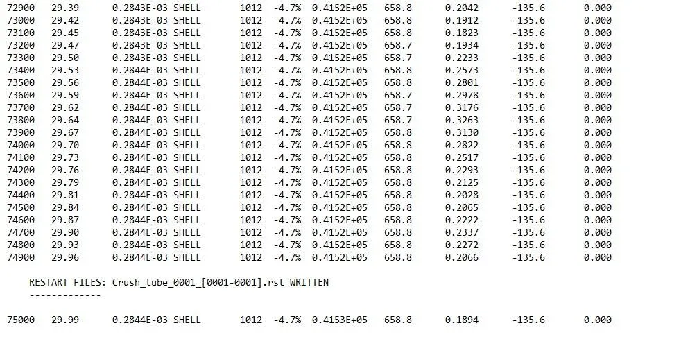
- After running Radioss, open hyperview and load the h3d file obtained, the Von-Mises contour plot can be obtained by, select "Contour" -> Result type = Von Mises(s) -> Averaging method = simple -> Apply.
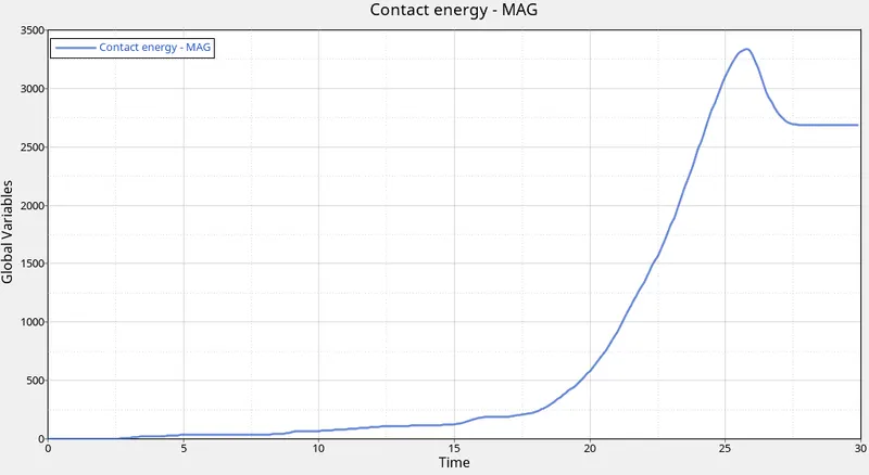
- To obtain the required graphs split the GUI and from "client selector" select HyperGraph 2D and in the data file load the T01 file obtained from simulation also for X type= time, Y type = Global variables, Y request = Internal energy, Kinetic energy, Hourglass energy, Total energy, y component = MAG and click on apply.
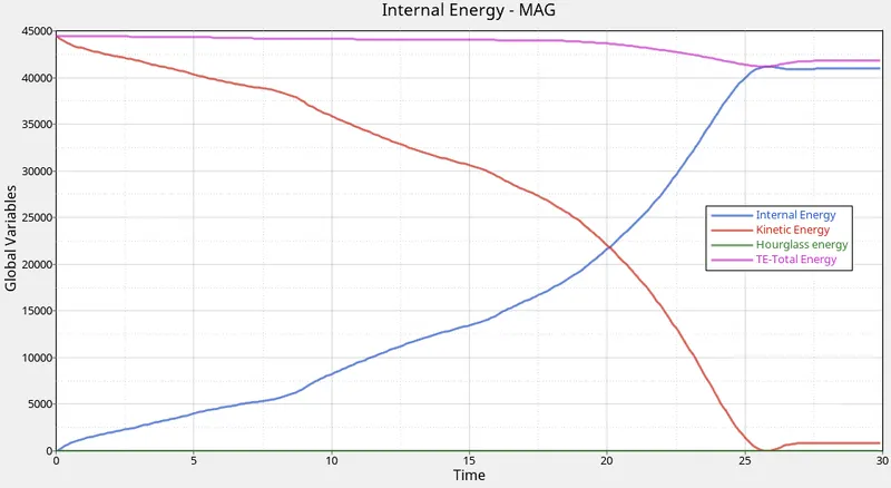
- For contact energy graph, X type= time, Y type = Global variables, Y request = Contact energy, y component = MAG and click on apply.
- For the rigid wall forces graphs, X type= time, Y type = Rigid wall/Rigidwallforce, Y request = 3 rwall, y component = NF- Resultant Normal Force, TF- Resultant Tangent Force and total resultant force, plot the 3 graphs individually.
- For the part, X type= time, Y type = Part, Y request = PSHELL1, PSHELL2, pshell_2mm, pshell2_2mm , Y component= Internal energy and click on apply.
CASE 5: Create a new notch in the middle, select the whole section and run.
- Open Hypermesh and import the Crush_tube_0000.rad file from CASE 4.
- To create notch in the middle, goto Tools -> translate -> nodes -> select the nodes -> direction X axis or Y axis and N1,N2 and N3 plane -> magnitude= 3 -> translate+/-.
- Save the file via export as RADIOSS file.
- In a new session import the modified Crush_tube_0000.rad file and go to Analysis -> Radioss -> Input = choose where the file will be stored -> Option = -nt 4 -> Radioss.
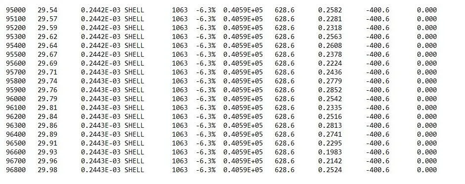
- After the analysis, open the engine file obtained Crush_tube_0001.out via notepad.
- After running Radioss, open hyperview and load the h3d file obtained, the Von-Mises contour plot can be obtained by, select "Contour" -> Result type = Von Mises(s) -> Averaging method = simple -> Apply.
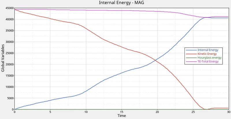
- To obtain the required graphs split the GUI and from "client selector" select HyperGraph 2D and in the data file load the T01 file obtained from simulation also for X type= time, Y type = Global variables, Y request = Internal energy, Kinetic energy, Hourglass energy, Total energy, y component = MAG and click on apply.
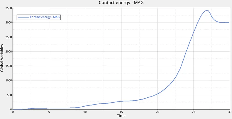
- For contact energy graph, X type= time, Y type = Global variables, Y request = Contact energy, y component = MAG and click on apply.
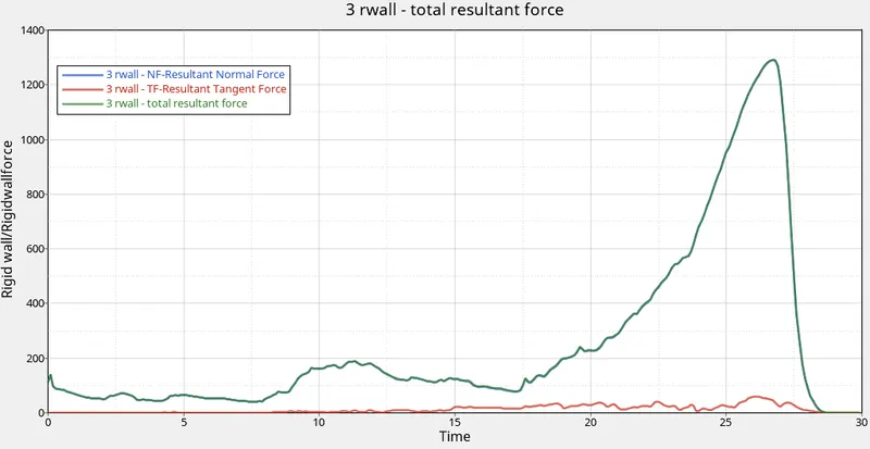
- For the rigid wall forces graphs, X type= time, Y type = Rigid wall/Rigidwallforce, Y request = 3 rwall, y component = NF- Resultant Normal Force, TF- Resultant Tangent Force and total resultant force, plot the 3 graphs individually.
- For the part, X type= time, Y type = Part, Y request = PSHELL1, PSHELL2, pshell_2mm, pshell2_2mm , Y component= Internal energy and click on apply.
CASE 6: Create a new notch with nodes only from opposing 2 faces and run.
- Open Hypermesh and import the Crush_tube_0000.rad file from CASE 4.
- To create notch on the both side of the tube by, goto Tools -> translate -> nodes -> select the nodes -> direction X axis -> magnitude= 3 -> translate+ for one side for other side translate -.
- Save the file via export as RADIOSS file.
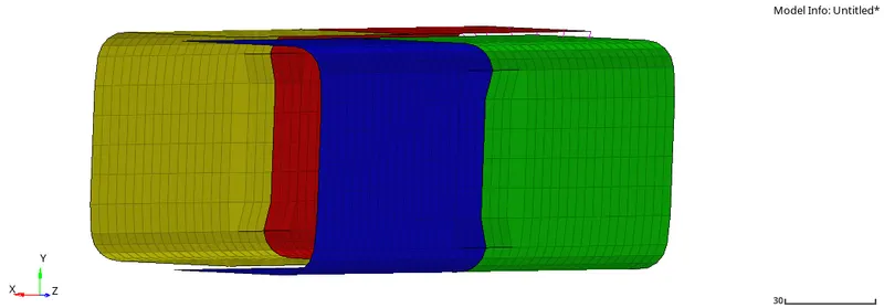
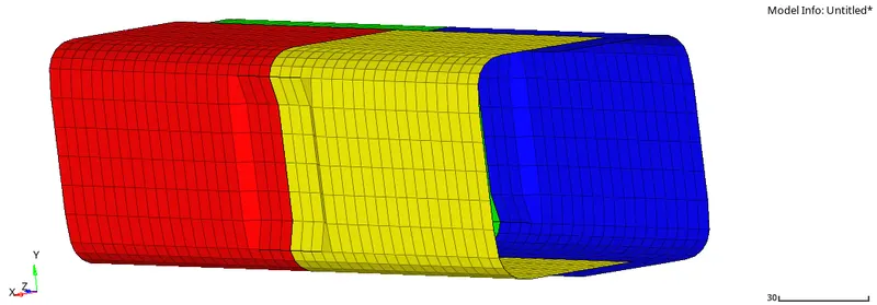
- Import the modified Crush_tube_0000.rad file into hypermesh and go to Analysis -> Radioss -> Input = choose where the file will be stored -> Option = -nt 4 -> Radioss.
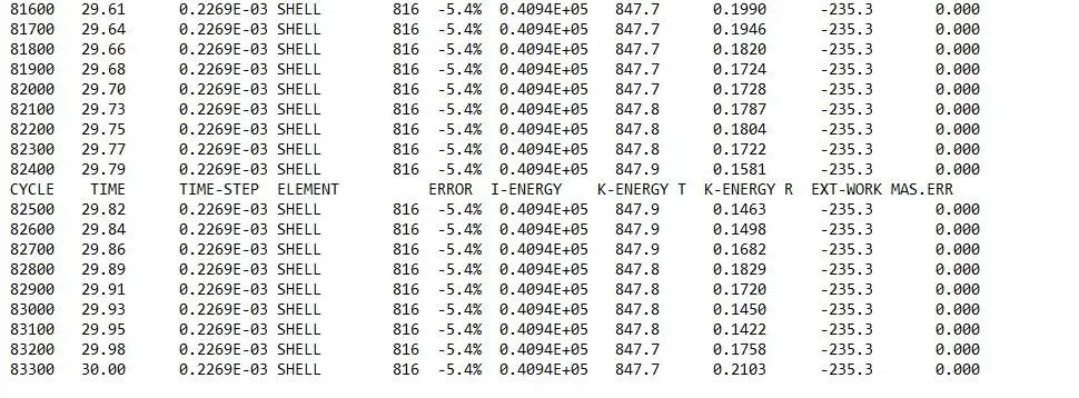
- After the analysis, open the engine file obtained Crush_tube_0001.out via notepad.
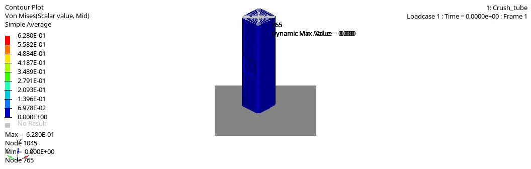
- After running Radioss, open hyperview and load the h3d file obtained, the Von-Mises contour plot can be obtained by, select "Contour" -> Result type = Von Mises(s) -> Averaging method = simple -> Apply.
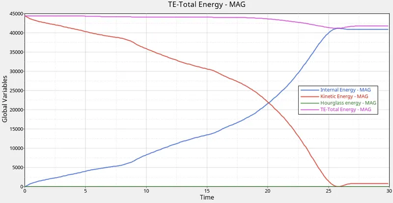
- To obtain the required graphs split the GUI and from "client selector" select HyperGraph 2D and in the data file load the T01 file obtained from simulation also for X type= time, Y type = Global variables, Y request = Internal energy, Kinetic energy, Hourglass energy, Total energy, y component = MAG and click on apply.
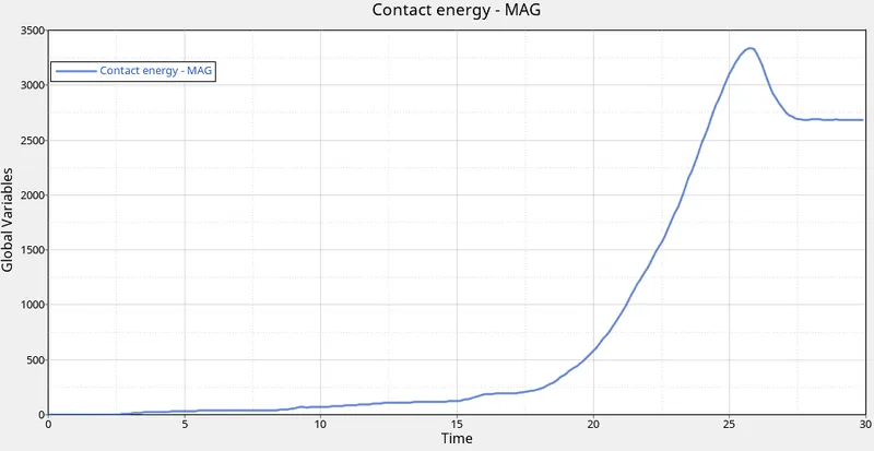
- For contact energy graph, X type= time, Y type = Global variables, Y request = Contact energy, y component = MAG and click on apply.
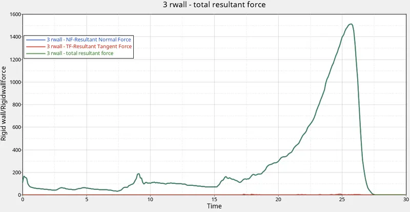
- For the rigid wall forces graphs, X type= time, Y type = Rigid wall/Rigidwallforce, Y request = 3 rwall, y component = NF- Resultant Normal Force, TF- Resultant Tangent Force and total resultant force, plot the 3 graphs individually.
- For the part, X type= time, Y type = Part, Y request = PSHELL1, PSHELL2, pshell_2mm, pshell2_2mm , Y component= Internal energy and click on apply.
RESULT:-
1. Comparison of cases
| CASE | Number of Cycles | Energy Error (%) | Mass Error (%) | Simulation Time (sec) |
| CASE 1 | 83600 | -3.8 | 0.0 | 261.27 |
| CASE 2 | 83600 | -3.8 | 0.0 | 252.90 |
| CASE 3 | 81800 | -4.8 | 0.0 | 280.84 |
| CASE 4 | 74900 | -4.7 | 0.0 | 199.51 |
| CASE 5 | 96800 | -6.3 | 0.0 | 267.59 |
| CASE 6 | 83300 | -5.4 | 0.0 | 282.33 |
In all the cases the energy errors are in the acceptable range.
2. Internal Energy
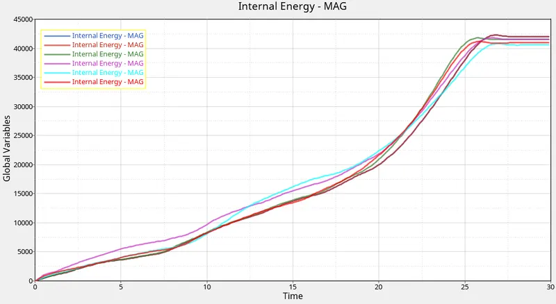
Case 1= Blue, Case 2= Brown, Case 3= Green, Case 4= Purple, Case 5= Cyan, Case 6= Red
In all the cases the kinetic energy decreases and internal energy increases but they reach their peak value at a different time which is dependent on the position of the notch also the increase in internal energy increases in an exponential way till reaching the peak value. It can be observed that Case 1 and 2 followed the same path and reached a peak at the same time but Case 3 and Case 6 reaches the peak early in comparison to all other cases.
3. Contact Energy
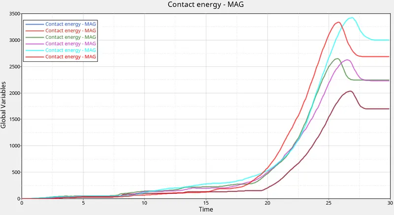
Case 1= Blue, Case 2= Brown, Case 3= Green, Case 4= Purple, Case 5= Cyan, Case 6= Red
The contact energy increases while the tube is crashing on to the wall after reaching the peak it slightly decreases, the increase of contact energy first follows a linear path but after a certain time, it rises exponentially till reaching the peak value. So Case 1 and 2 had experienced the least contact energy while Case 5 had experienced highest contact energy.
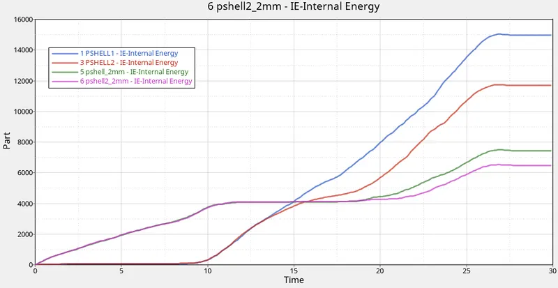
4. Part Internal Energy
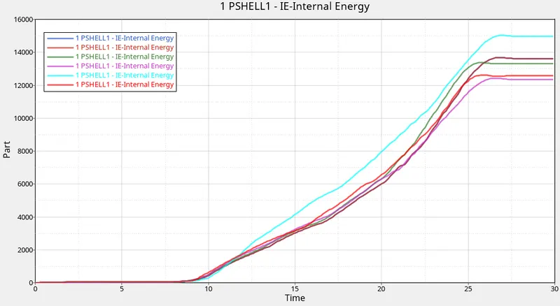
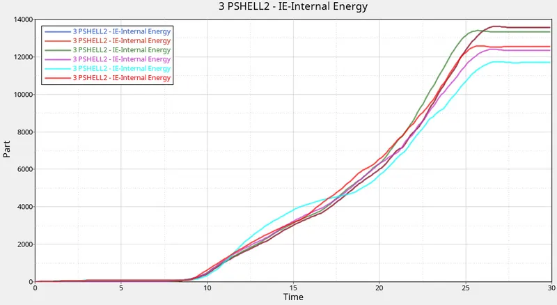
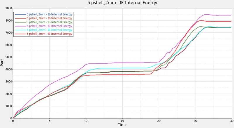
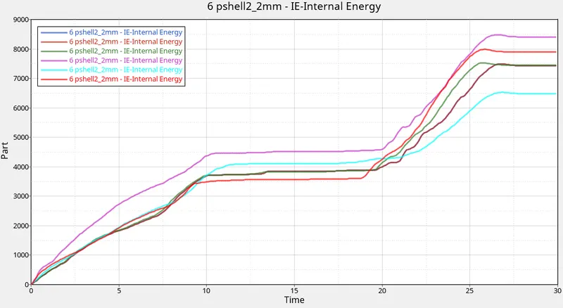
Case 1= Blue, Case 2= Brown, Case 3= Green, Case 4= Purple, Case 5= Cyan, Case 6= Red.
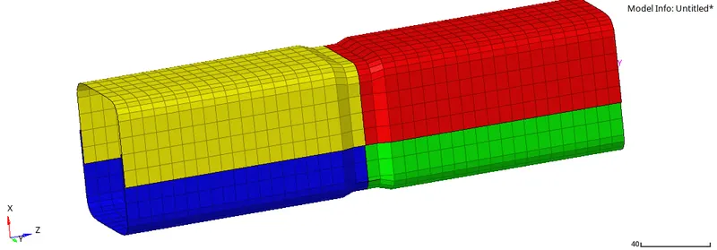
1 PSHELL1= Green part, 3 PSHELL2= Red part, 5 pshell_2mm= Blue part, 6 pshell2_2mm= Yellow part.
From the first 2 graphs, it can be observed that the Green and Red part do not show any increase in energy initially but after a brief interval, it increases exponentially until it reaches the peak this is because the upper part does not deform first but that is why initially energy increase is near to zero but when it starts to deform it increases exponentially but for the Blue and Yellow part as it experiences deformation from the initial stage the graph increases exponentially for some duration but becomes linear until the completion of above Green and Red part deformation than again it starts deforming until it reaches the peak value. It can be observed from the graph that the Case 1 and 2 follows the same path but for Case 4 which do not have any notch have experienced maximum internal energy and also the time is taken to reaches the peak value is highest while Case 6 reaches the peak of the curve in less time in comparison to the others.
5. Rigid Wall Forces
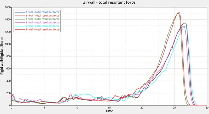
Case 1= Blue, Case 2= Brown, Case 3= Green, Case 4= Purple, Case 5= Cyan, Case 6= Red
From the rigid wall force graph for all the cases, it can be clearly observed that the Case 6 having a notch on both sides experienced the highest amount of forces while the duration is less in comparison to other cases but for the Case 4 which do not have any notch experienced the least force. The initial stage of all the cases shows peaks and valleys in the curve which suggest the component is being crashed to a surface, the peak occurs when the complete crash scenario is finished and the all the curves return to zero.
(II) Meshing of the Bumper
- Open hypermesh and open the bumper model directly as it is in ".hm" type.
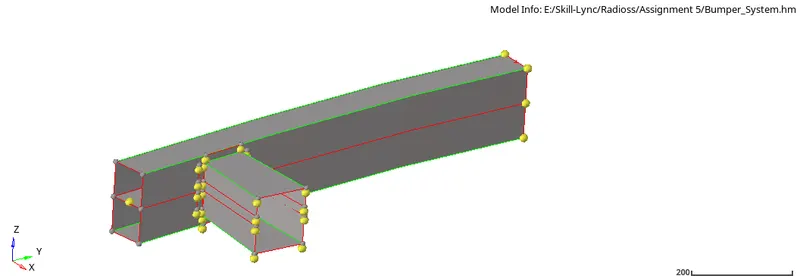
- As the bumper beam is not connected to the front and rear part it can be connected by geom -> surface edit -> trim with surface/plane -> with surface
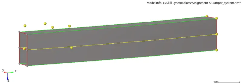
- And for the crash box toggle option can be used present under geom -> quick edit.
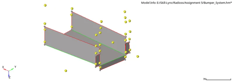
- To mesh the component 2D -> automesh -> surface -> element size= 6, mesh type= quad -> select the component -> mesh.
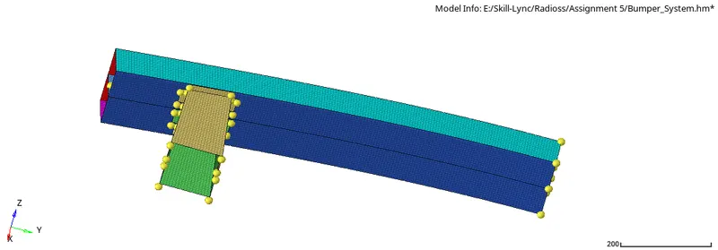
- Create a new component tab and under tool -> reflect -> element -> right click and duplicate the elements -> y axis with base -> reflect.
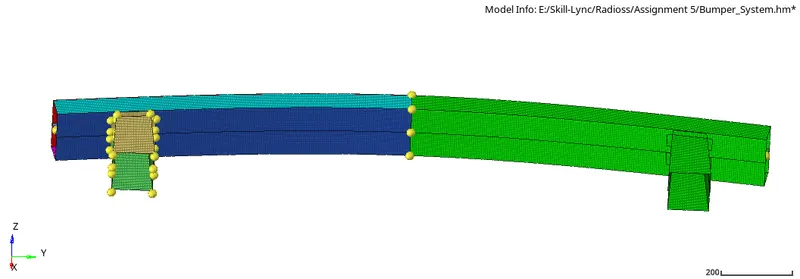
- Open edge can be removed using Tool -> edges.
CONCLUSION:-
So by completing the crush tube analysis the effect of position of notch in the crash tube is studied with the different type of interface type 7 and 11 and it is found that where the notch is present the energy is absorbed more quickly and absorption intensity is also maximum. Also, the bumper has meshed for the given criteria.