Assignment 3- Simulate a crash beam with and without default parameter and compare the the results obtained in Radioss
Objective:- To run crash beam file with and without given parameter and compare the resulting outputs.
CASE 1
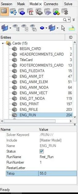
1. Using the crash beam file change the run time to 55 ms.
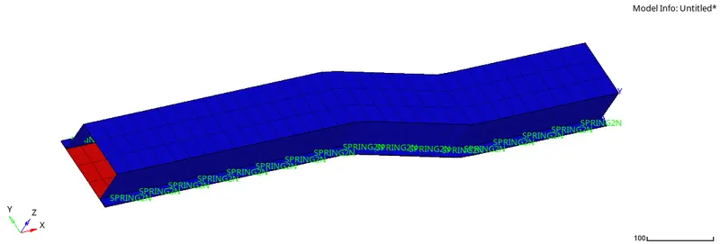
- Open Hypermesh and import the solver deck file Element_Formulation-Shell-3_assignment_0000.rad.
- To change the run time, under Entities got to Cars Tab and click on ENG_RUN and change Tstop to 55.
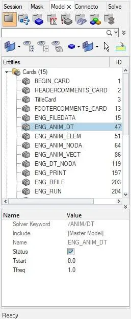
2. Change the number of animation steps during simulation to a minimum of 25 and maximum of 60.
- Have to choose any number for animation steps during simulation from a minimum 25 and maximum 60
- So, for 55 number of animation step the frequency will be `Tf req = 55/55 =1`
- Under ENG_ANIM_DT, change the Tfreq = 1
3. Run the base simulation without any modification to element properties.
- To run the simulation, under Analysis goto Radioss -> Input file= provide path where the data will be stored -> Export option= all -> Run option= analysis -> Run number= 1 -> Options= -nt 4 -> Click on Radioss
- The generated output files will be stored in the file location provided.

4. At the end of the simulation, do the energy error and mass error checks and determine whether results would be acceptable.
- After the completion of the simulation, the energy error and mass error can be checked by going to the output file location and opening the engine file named "Element_Formulation-Shell-3_assignment_0001.out" as notepad file.
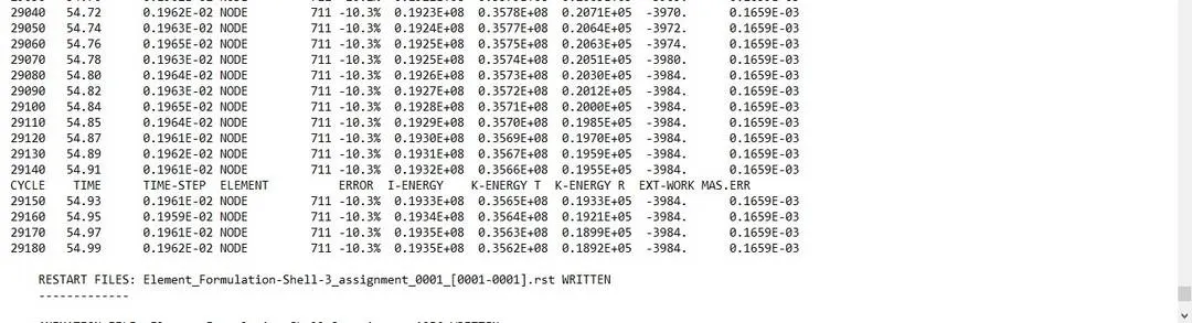
- It can be seen that the energy error is -10.3% and the mass error is `0.1659*10^-3` and for energy error, the acceptable range is 5% to -15%. So the obtained errors are in an acceptable range.
5. If acceptable, Plot rigid wall forces, internal energy, hourglass energy, contact energy, the total energy of the simulations.
- Since the errors are in the acceptable range required plots can be generated by in the "Client selector" change HyperMesh to HyperView, in HyperView load the "*.h3d" file generated from the simulation.
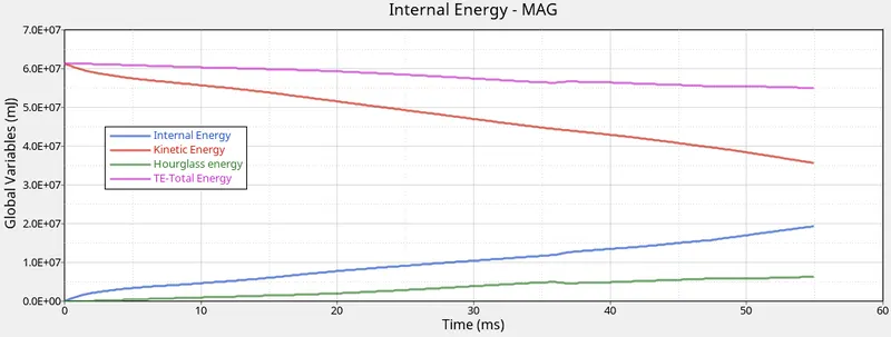
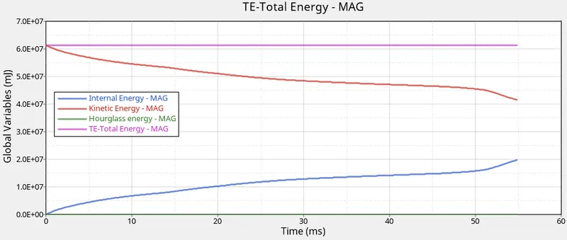
- To obtain the required graphs split the GUI and from "client selector" select HyperGraph 2D and in the data file load the T01 file obtained from simulation also for X type= time, Y type = Global variables, Y request = Internal energy, Kinetic energy, Hourglass energy, Total energy, y component = MAG and click on apply.
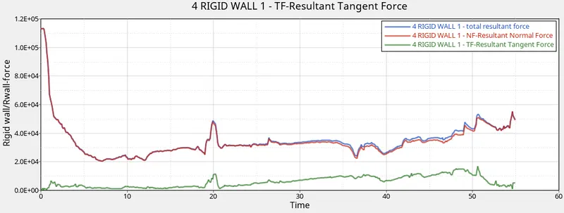
- For the rigid wall forces graphs, X type= time, Y type = Rigid wall/Rwall-force, Y request = 4 RIGID WALL 1, y component = NF- Resultant Normal Force, TF- Resultant Tangent Force and total resultant force, plot the 3 graphs individually.
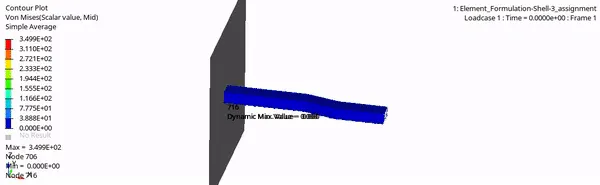
- The Von-Mises contour plot can be obtained by select "Contour" -> Result type = Von Mises(s) -> Averaging method = simple -> Apply
CASE 2
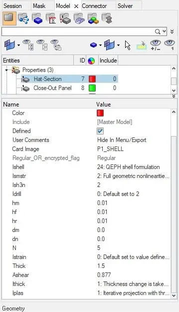
6. Change all the shell elements properties to recommended properties, save this as separate rad files and run the simulation.
Recommended properties:
| Parameters | Comment | |
|
Ishell =24 |
QEPH 4 nodes shells are the best combination of cost and accuracy. | |
|
Ismstr=2 |
Full geometric nonlinearities (default)with possible small strain formulation activation in RADIOSS Engine. | |
|
Ish3n=2 |
Standard 3 noded shell (C0)with modification for large rotation(default) |
|
| N=5 | A number of integration points set to 5 for accuracy bending. | |
|
Ithick=1 |
Thickness change is taken into account for accuracy. |
|
|
Iplas=1 |
Iterative plasticity for good accuracy. |
- Import the solver deck file Element_Formulation-Shell-3_assignment_0000.rad and to change the parameters in the property card for the "Hat section" and "Close-out panel".
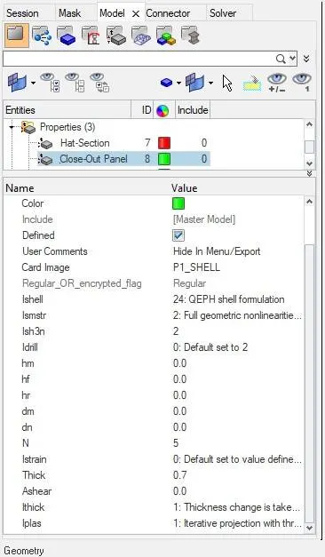
- For the ENG_RUN, Tstop = 55 and ENG_ANIM_DT, Tfreq = 1, generate the .out file by Analysis -> Radioss.
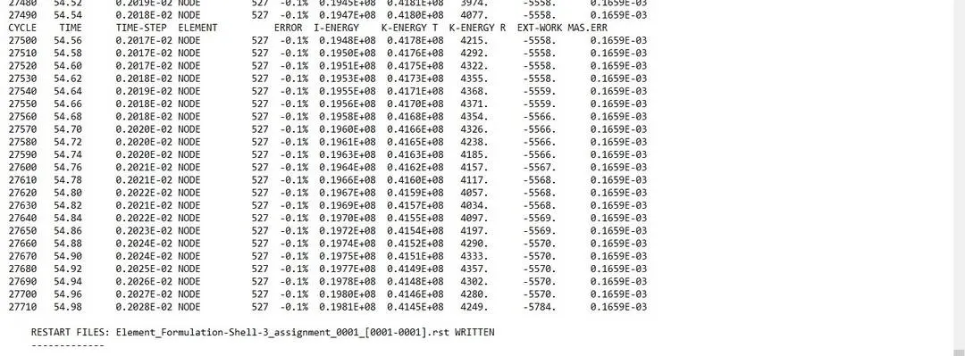
- After the completion of the simulation, the energy error and mass error can be checked by going to the output file location and opening the engine file named "Element_Formulation-Shell-3_assignment_0001.out" as notepad file.
- It can be seen that the energy error is -0.1% and the mass error is `0.1659*10^-3`
- Plot rigid wall forces, internal energy, hourglass energy, contact energy, the total energy of the simulations.
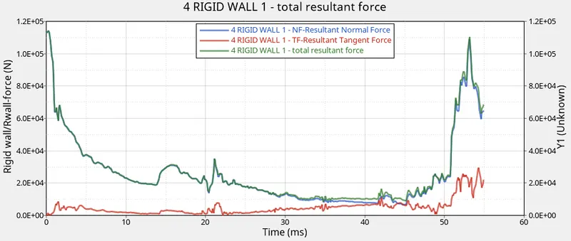
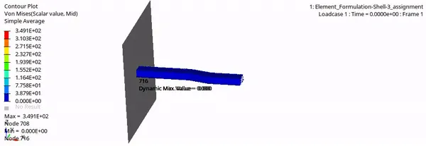
- The Von-Mises contour plot
8. Comparison of all the results from both the simulations, whether there is any change in the results and why there is any change in the result.
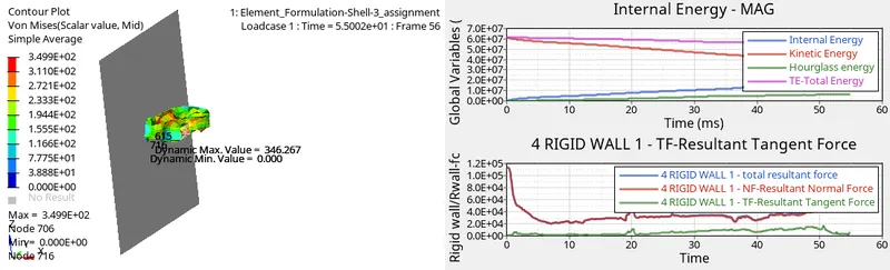
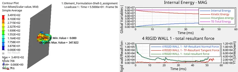
- The total energy in case 1 slightly decreases but in the case 2 remains constant because in case 1 the hourglass energy there is a decrease in total energy but in case 2 there is no hourglass energy so the total energy appears to be constant.
- The kinetic energy in the system is decreasing while the internal energy is increasing if the simulation is allowed to run for a long time than for case 1 the kinetic energy will reach zero and the internal will tend to reach the maximum value but won't reach completely because of the energy error but for case 2 as there is no or little energy error the internal energy will reach maximum.
- It can also be observed that due to change in property parameters the energy error is improved from case 1 -10.3% to case 2 -0.1%.
- The hourglass energy can be avoided by better element formulation here in case 2 QEPH 4 is used which completely reduced the hourglass energy.
- From the rigid wall forces obtained in both the cases, it can be observed that for case 1 as the simulation progress the normal force decreases and there is little variation as the property parameters are kept default but in case 2 as the elements property parameters are changed it can be observed that there is a huge spike in normal and tangent force because of the improvement in the shell element formulation.
- Due to the improvement in the shell element formulations, the von mises also decreases from case 1 3.499*10^2 to case2 3.491*10^2.
9. Explanation on hourglass energy, its causes and the steps to avoid it.
Hourglass modes are element distortions that have zero strain energy. Thus, no stresses are created within the element. As it is nonphysical modes of deformation that occur in under integrated elements and produce no stress, by under integrated, it means that the solid elements with a single point of integration or shell or thick shell elements with a single in-plane integration point.
Under-integrated elements are very familiar in crashworthiness. In these elements, a reduced number of integration points are used to decrease the computation time. This simplification generates zero energy deformation modes, called hourglass modes.
- Perturbation or penalty method (Q4):
Hourglass control by application of anti-hourglass forces to maintain deformation stability of the element (historical method).
- When the hourglass deformation is detected with the relative motion of the nodes, a force is applied on the node to stabilize the deformation.
- This force is defined according to the element stiffness (young's modulus, yield stress etc) and this force will introduce artificial energy named hourglass energy.
- This method is used for high velocity/high strain rate problem.
- Physical stabilization or Stiffness method (QEPH):
Hourglass control by the correction of internal energy in an analytical way.
- The hourglass treatment is done at the material level
- The hourglass loading stiffness depends on the natural tangent modulus and the stiffness is added to the material.
The choice of hourglass formulation plays an essential role in the quality of results. If the mesh is fine enough, the physical stabilization method can be used.
Result-
From Case 1
From Case 2
Conclusion-
So by completing this assignment, I learnt about hourglass energy and how it affects the internal energy and kinetic energy, how element formulation can be done to reduce hourglass energy, also performed simulations with and without changes in the element parameters and plot the required graphs using HyperView and Hypergraph 2D and compared the obtained results.