Comparison of crash results of a rail with Base Simulation and Improved shell element properties
PROJECT REPORT
SKILL LYNC ASSIGNMENT 3
Aim:
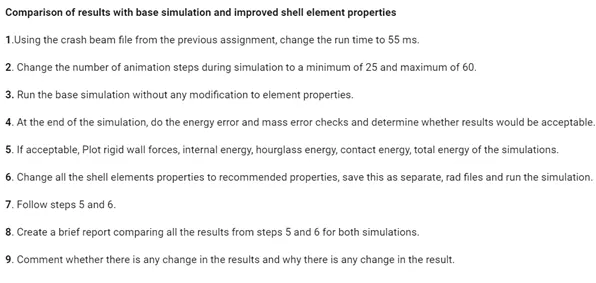
To run the crash simulations of a rail using RADIOSS with the default property values and then the edited different property values, and compare the results using graphical plots of different kinds.
Objective:
Theory:
What is RADIOSS?
Altair RADIOSS is a multidisciplinary finite element solver developed by Altair Engineering.[1] It can solve both linear and non-linear problems. It is a finite element solver using implicit and explicit integration schemes for the solution of engineering problems, from linear statics and linear dynamics to nonlinear transient dynamics and mechanical systems. This multidisciplinary solver enables designers to maximize performance related to durability, NVH, crash, safety, manufacturability, and fluid-structure interaction, in order to bring products to market faster.
RADIOSS’ analysis capabilities for linear and non-linear finite element analysis, sheet metal stamping, and multi-body dynamics are accessible via two input formats.
What is Finite Element Analysis?
Finite element analysis (FEA) is the process of simulating the behaviour of a part or assembly under given conditions so that it can be assessed using the finite element method (FEM). FEA is used by engineers to help simulate physical phenomena and thereby reduce the need for physical prototypes, while allowing for the optimisation of components as part of the design process of a project.
FEA uses mathematical models to understand and quantify the effects of real-world conditions on a part or assembly. These simulations, which are conducted via specialised software, allow engineers to locate potential problems in a design, including areas of tension and weak spots.
What is a time step in FEA?
In the context of explicit analysis, time step is the time required for a shock wave to propagate across the smallest distance of the element. A run is a single model simulation and it starts at time zero and continues till the user defined endpoint is reached. The basic time unit in the run is the time step.The time step is directly dependent on the length of the element and inversely proportional to the speed of sound of material. The speed of sound of the material is dependent on both material modulus and density of the material. So, if the material is stiffer (higher modulus of elasticity), the speed of sound increases resulting in a lower solution time step.
`c=(E/rho)^0.5`
`t=l/c`
Here the symbols have their usual meanings.
Hourglassing and Hourglass Deformation:
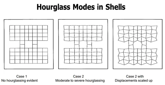
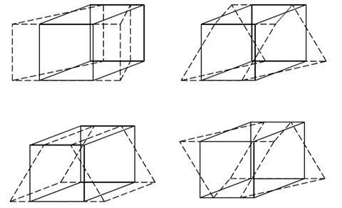
Hourglass deformation is a kind of deformation that takes place in the elements which are under integration and no stresses are produced, they are zero-energy modes of deformation that produce zero strain and no stress. Hourglass modes occur only in under-intetgrated solid, shell, and thick shell elements with a single integration point. This leads to inaccurate stress, strain and deflection results. The phenomenon of Hourglass Deformation is called Hourglassing.
Methods to prevent Hourglassing:
There are 2 methods to control Hourglass deformation:
- Perturbation Method
- Physical Stablization
The explanations of these methods is:
Perturbation Method: In this method the hourglass deformation is detected with the relative motion (velocity) of the nodes. After the detection of deformation a force is applied to the element which opposes the deformation, the value of this force is in accordance with the physical properties of the material such as stiffness and Youngs modulus etc. This force introduces an artificial energy in the material which is called hourglass energy. This method is mostly used for Q4 elements. This method is used in high velocity or high strain rate involving problems like in explosives. The Q4 elements may have bad behaviour in case of large rotation and distortion and in case of elastic load-unloading cycles.
Physical Stabilization: In QEPH method, the stiffness is added directly to the element and it effects the material property directly as it is done on the material level. Hourglass yield depends on natural yield. Hourglass loading stiffness is dependent on natural tangent modulus It is not used in orthotropic materials. Normally it is used in low velocity applications. The QEPH elements give accurate results in case of loading and unloading even if there is hourglass mode deformation.
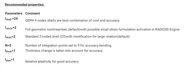
Key Parameters on/PROP/SHELL:
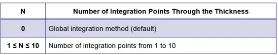
- Ishell: Used to select element formulation for 4-noded shells
- Ish3n: Used to select element formulation for 3-noded shells
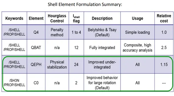
- N: Used to choose number of integration points through the thickness, its value is usually taken between 1 to 10 through the thickness. By default the value is 0.
- Ismstr: For specifying small or large strain formulation

- Iplas: Choose method for calculating post-yield strains

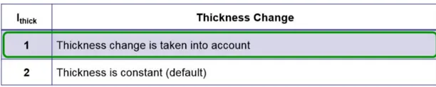
- Ithick: Determine if thickness is constant under load
Shell stress calculation:
From the deformation of elements the strain is calculated and from this strain, the stress values are calculated. With these computed stress values, the Von Mises stress is computed and compared to the yield stress of the material. If the Von Mises stress is smaller than yield stress, the computed stress is the one used in order to compute the internal force of the elements.
The Von Mises stress is given by:
`σ(Von Mises)= 〖σ(x)〗^2+〖σ(y)〗^2+3〖σ(xy)〗^2-σ(x)σ(y)`
Given Model:
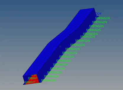
Now, the steps/workflow to solve the problem given are as follows:
- Import the model.
- Go to Cards > ENG_RUN and enter the value of Tstop as 55 ms.
- Go to ENG_ANIM_DT and change the value of Tstart to 0 and Tfreq to 1 (we have taken 55 animation steps) or as required as per the case. The element formulation properties were not edited and default values were taken which were in /DEF_SHELL.
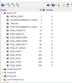
4. Go to Analysis > Radioss, and select a destination file to store the Run files, set Option to -nt4 so that the simulation runs with 4 CPUs.
5. Now click on Radioss to run the simulation.

6. The Radioss block running comes in a new window:
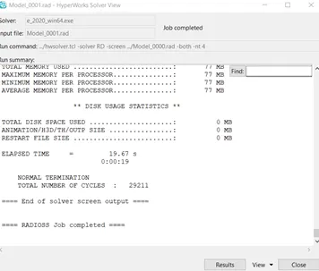
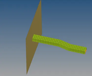
7. Now save the model, and open the hyperworks window and load the saved .h3d file to see the animation. The simulation setup with the wall is as follows:
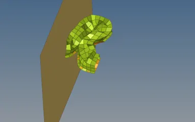
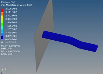
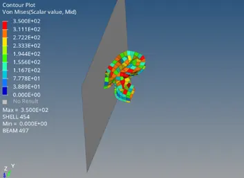
8. On playing the animation, we get a crushed rail, whose progress approximately at the midtime and at the end of the animation run i.e. t = 55ms is as follows :
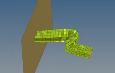
Energy and mass error checks in this case :
For checking errors the .0001 notepad file was accesed the the error values were noted down.
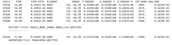
- Energy error = -10.3%
- Mass Error =`0.1659×10^(-3)`
CONTOURS PLOTS:
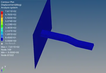
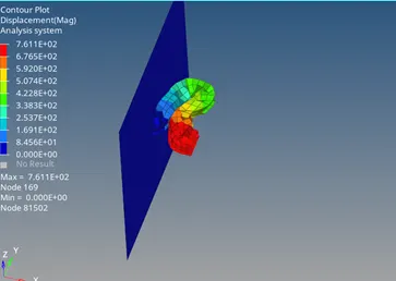
Displacement Contour Plot:
Von Mises Contour Plot:
VARIOUS ENERGY PLOTS:
Plot 1: Following energy variations are shown in the plot below:
- Internal Energy vs Time
- Kinetic Energy vs Time
- Contact Energy vs Time
- Hourglass Energy vs Time
- Total Energy vs Time
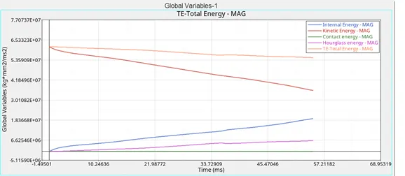
Due to reduction in speed from t=0 to t=55 ms, the kinetic energy decreases, and due to the deformations in elements, the hourglass energy is increases, also the Internal energy also increases.
Plot 2: Following force variations are shown in the plot below:
- Resultant Normal Force vs Time
- Resultant Tangent Force vs Time
- Total Resultant Force vs Time
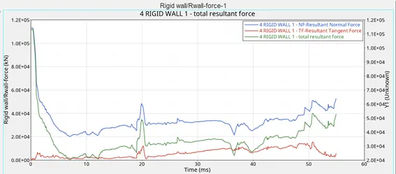
This is the total analysis of the beam crash with the default Shell element formulation properties.
Now we change the Shell element formulation properties as per the recommended values provided and see the results.
We repeat the similar steps as above, before and after entering the new Element formulation properties.
Now, the steps/workflow to solve the problem given are as follows:
- Import the model.
- Go to Cards > ENG_RUN and enter the value of Tstop as 55 ms.
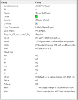
- Go to ENG_ANIM_DT and change the value of Tstart to 0 and Tfreq to 1 (we have taken 55 animation steps) or as required as per the case. The element formulation properties were edited as per the recommended values as given below:
- Ishell = 24
- Ismstr = 2
- Ish3n = 2
- N = 5
- Ithick = 1
- Iplas = 1
- Go to Properties and select the components one by one and enter the above values in properties:
5. Go to Analysis > Radioss, and select a destination file to store the Run files, set Option to -nt4 so that the simulation runs with 4 CPUs.
6. Now click on Radioss to run the simulation.
7. The Radioss block running comes in a new window:
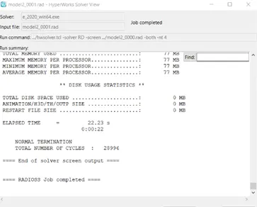
8. Now save the model, and open the hyperworks window and load the saved .h3d file to see the animation.
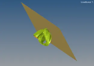
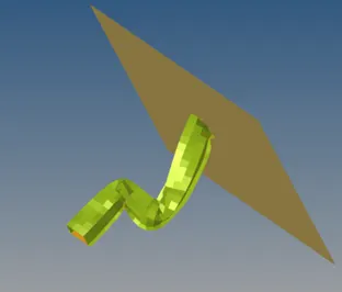
9. On playing the animation, we get a crushed rail, whose progress approximately at the midtime and at the end of the animation run i.e. t = 55ms is as follows :
Energy and mass error checks in this case :
For checking errors the .0001 notepad file was accesed and the error values were noted down as before.
- Energy error = -0.1%
- Mass Error = `0.1659×10^(-3)`
CONTOURS PLOTS:
Displacement Contour Plot:
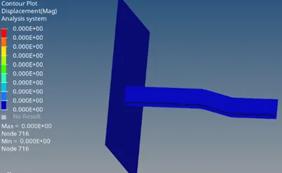
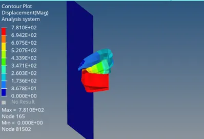
Von Mises Contour Plot:
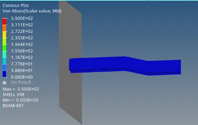
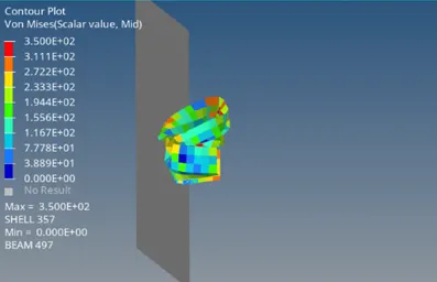
VARIOUS ENERGY PLOTS:
Plot 1: Following energy variations are shown in the plot below:
- Internal Energy vs Time
- Kinetic Energy vs Time
- Contract Energy vs Time
- Hourglass Energy vs Time
- Total Energy vs Time
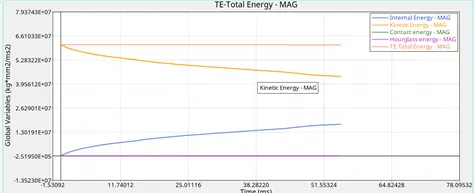
The Hourglass energy here is 0, because of better properties given to the elements. As the increase in Internal energy is almost equal to the decrease in Kinetic Energy, so the total energy suffers a very minute change
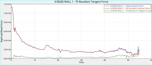
Plot 2: Following force variations are shown in the plot below:
- Resultant Normal Force vs Time
- Resultant Tangent Force vs Time
- Total Resultant Force vs Time
COMPARISON OF 2 CASES:
Unit System: kg mm ms
|
PARAMETER |
Case 1 |
Case 2 |
|
Von Mises Stress |
350 |
350 |
|
Displacement |
761.1 |
781 |
|
Internal Energy |
Increases |
Increases |
|
Hourglass Energy |
Increases |
0 |
|
Contact Energy |
0 |
0 |
|
Kinetic Energy |
Decreases |
Decreases |
|
Total Energy |
Decreases |
Almost Constant |
|
Mass Error |
`0.1659×10^(-3)` | `0.1659×10^(-3)` |
|
Energy Error |
-10.3% |
-0.1% |
RESULT:
Several values obtained for different parameters are plotted on the graphs above. A comparison is done in the table above about the difference between the charactaristics of various comparison parameters between the two cases of simulation.
- Energy Error in First case : -10.3%
- Energy Error in Second case : -0.1%
CONCLUSION:
Doing crash analysis using Radioss is one of the best methods to predict and hence alter the safety parameters as well as properties of different things. In this project we did a crash analysis of a rail/beam using 2 different sets of material properties and parameters. Different results obtained were mentioned at appropriate places in the report. The error in the energy was reduced by a significant amount. Comparison between Von Mises stress, different energies and errors was done and properly analyses and acceptable results were obtained.